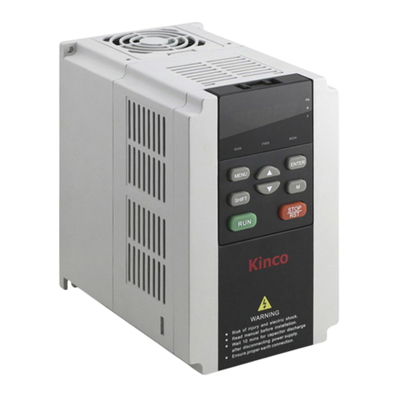
Kinco FV100 Series User Manual
Vfd
Hide thumbs
Also See for FV100 Series:
- User manual (133 pages) ,
- User manual (20 pages) ,
- User manual (14 pages)
Table of Contents
Advertisement
Advertisement
Chapters
Table of Contents

Related Manuals for Kinco FV100 Series


Summary of Contents for Kinco FV100 Series
-
Page 2: Table Of Contents
目录 第一章 安全信息 .................. 2 第二章 产品介绍 ................. 3 2.1 铭牌介绍 ................. 3 2.2 型号说明 ................. 3 2.3 外形尺寸及毛重 ................4 2.3.1 变频器的外形尺寸及毛重 ............. 4 2.3.2 操作面板及安装盒尺寸 ............... 6 第三章 安装环境及外围配置 ............... 7 第四章 变频器的配线安装指导 ..............8 4.1 主回路端子配线及配置 ..............8 4.1.1 主回路输入输出端子类型... -
Page 3: 第一章 安全信息
第一章 安全信息 第一章 安全信息 危险 注意 ·必须由具有专业资格的人进行配线作业,否则有触 ·严禁安装在水管等可能产生水滴飞溅的场合,否则 电的危险。 有损坏财物的危险。 ·应在断开电源 10 分钟后进行维护操作,此时充电指 ·不要将螺钉、垫片及金属棒之类的异物掉进变频器 示灯彻底熄灭或确认正负母线电压在 36V 以下,否 内部,否则有火灾及损坏财物的危险。 则有触电的危险。 ·不要安装在阳光直射的地方,否则有损坏财物的危 ·操作配线或者安装变频器时,请确认电源是否关闭, 险。 否则有触电的危险。 ·不要将 +//B1 与-短接,否则有发生火灾和损坏财物 ·禁止自行改装变频器内部的零件或线路。 的危险。 ·严禁将控制端子中 R1a 、 R1b 、 R1c 以外的端子接上 交流 220V 信号,否则有损坏财物的危险。 · B1 和 B2 端子之间用于连接制动电阻,不允许短路, 否则可能会造成变频器制动单元损坏。... -
Page 4: 第二章 产品介绍
第二章 产品介绍 第二章 产品介绍 本章介绍了 FV100 系列的产品规格、型号、结构等基本产品信息。 2.1 铭牌介绍 功率 机种名称 输入端电压/电流/频率范围 输出端电压/电流/频率范围 CE 认证 序号 2.2 型号说明 FV100 – 4T– 0075G/0110L –U–000 软件订制代码 FV:FV 系列 硬件订制代码 第一代产品 00:标准型 0075G:7.5KW 恒转矩/重载 „„其他特种型号 0110L:11KW 变转矩/轻载 2:供电电压 220V S:单相 4:供电电压 380V T:三相 „„... -
Page 5: 外形尺寸及毛重
第二章 产品介绍 2.3 外形尺寸及毛重 2.3.1 变频器的外形尺寸及毛重 图 2-1 FV100-4T-0037G/0055L 以下功率变频器 图 2-2 FV100-4T-0055G/0075L~FV100-4T-4000G/4500L... - Page 6 第二章 产品介绍 表 2-1 机械参数表 变频器型号 外形和安装尺寸(mm) 大概重量 (G:恒转矩负载; 安装孔 (毛重、kg) L:风机水泵负载) FV100-2S-0004G FV100-2S-0007G FV100-2S-0015G FV100-2S-0022G FV100-2T-0004G FV100-2T-0007G FV100-2T-0015G FV100-2T-0022G FV100-2T-0037G FV100-4T-0007G/0015L FV100-4T-0015G/0022L FV100-4T-0022G/0037L FV100-4T-0037G/0055L FV100-2T-0055G FV100-2T-0075G FV100-4T-0055G/0075L FV100-4T-0075G/0110L FV100-2T-0110G FV100-4T-0110G/0150L FV100-4T-0150G/0185L FV100-4T-0185G/0220L FV100-2T-0150G FV100-2T-0185G FV100-2T-0220G FV100-4T-0220G/0300L FV100-4T-0300G/0370L FV100-4T-0370G/0450L 88.5 FV100-4T-0450G/0550L FV100-4T-0550G/0750L 102.5...
-
Page 7: 操作面板及安装盒尺寸
第二章 产品介绍 FV100-4T-0900G/1100L FV100-4T-1100G/1320L FV100-4T-1320G/1600L FV100-4T-1600G/1850L FV100-4T-1850G/2000L FV100-4T-2000G/2200L FV100-4T-2200G/2500L FV100-4T-2500G/2800L 1006 FV100-4T-2800G/3150L FV100-4T-3150G/3550L FV100-4T-3550G/4000L 1228 1196 FV100-4T-4000G/4500L 2.3.2 操作面板及安装盒尺寸 图 2-3 安装盒尺寸... -
Page 8: 第三章 安装环境及外围配置
第三章 安装环境及外围配置 第三章 安装环境及外围配置 安装间隔及距离要求,如图 3-1 和图 3-2 所示。 风扇排气 > 3 5 c m 风 扇 排 气 > 1 0 c m > 5 c m > 1 5 c m > 1 5 c m > 5 c m >... -
Page 9: 第四章 变频器的配线安装指导
第四章 变频器的配线安装指导 第四章 变频器的配线安装指导 4.1 主回路端子配线及配置 4.1.1 主回路输入输出端子类型 表4-1主回路端子描述 子名称 功能说明 L、N 单相交流 220V 输入端子 R、S、T 三相交流 220V/380V 输入端子 ○ 直流负母线输出端子 一 ○ 1、○ 外接直流电抗器预留端子 十 十 ○ 2、○ 外接制动单元端子 十 一 B1、B2 制动电阻的接入端子 U、V、W 三相交流输出端子 屏蔽接地端子... -
Page 10: 基本运行配线连接
第四章 变频器的配线安装指导 4.1.2 基本运行配线连接 图 4-1 基本配线图 (外接、选配件)制动电阻 J601 J602 J603 J604 断路器 2/B1 三相交流电源 主回路 电源接地 电机接地 AO1 AO2 控制回路 多功能输入选择1 直流电压/电流表 多功能输入选择2 电压/电流信号 多功能输入选择3 多功能输入选择4 多功能输入选择5 多功能输入选择6 输出0-24V脉冲信号 多功能输入选择7 输出 双向开路集电极输出 +10V 公共端 模拟输入 AI1/AI2 可编程继电器输出 AI3+ 模拟差分输入 -10V--+10V AI3- 485+... - Page 11 第四章 变频器的配线安装指导 各端子功能说明请参见表 4-3。 表4-3接口板端子 CNA 功能表 类别 端子丝印 名称 端子功能说明 规格 用于端子接线屏蔽层接地。模拟信号线、 屏蔽 屏蔽接地 485 通讯线、 电机电缆线的屏蔽层可接在此 在内部与主回路接线端子 PE 相连 端子 +10V 电源 对外提供+ 10V 参考电源 最大允许输出电流 5mA 电源 +10V 电源地 模拟信号和+ 10V 电源的参考地 内部与 COM 、 CME 隔离 接受模拟电压量或电流量单端输入,电压...
- Page 12 第四章 变频器的配线安装指导 类别 端子丝印 名称 端子功能说明 规格 多功能输入端子 1 光耦隔离输入 输入阻抗 :R = 3.3 kΩ ; X1~X6 最 多功能输入端子 2 高输入频率 :200Hz ; X7 最高输入 多功能输入端子 3 频率 100kHz 多功 可编程定义为多种功能的开关量输入端子 , 输入电压范围 :20~30V 能输 多功能输入端子 4 开关量输入端子 (A6 组 ) 中对 A6.00~A6.06 入端...
-
Page 13: 第五章 变频器快速操作指南
第五章 变频器快速操作指南 第五章 变频器快速操作指南 5.1 变频器操作面板 5.1.1 操作面板的外观及按键功能说明 操作面板是变频器接受命令、显示参数的主要单元,为 LED 型。LED 型操作面板见图 5-1。 运行指示灯 命令通道指示灯 确认键 菜单键 增减键 移位键 多功能键 运行键 停机/复位键 图 5-1 LED 操作面板示意图 变频器操作面板上设有 8 个按键,每个按键的功能定义如表 5-1 所示。 表5-1操作面板功能表 键 名称 功能 编程 / 退出键 进入或退出编程状态 MENU 功能... -
Page 14: Led 数码管及指示灯说明
第五章 变频器快速操作指南 5.1.2 LED 数码管及指示灯说明 辑状态按两级菜单方式进行显示, 其顺序依次为:功能码 组或功能码号→功能码参数,按 ENTER 键可进入功能 变频器 LED 操作面板上设有五位 8 段 LED 数码管、3 参数显示状态。在功能参数显示状态下,按 ENTER 键 个单位指示灯、3 个状态指示灯。如图 5-1 所示。数码 则进行参数存储操作;按 MENU 则可反向退出。 管可显示变频器的状态参数、功能码参数、故障告警码 等。 3 个单位指示灯分别对应 3 种单位指示。 3 状态指示 5.1.4 操作面板的操作方法 灯:分别指示的意义说明见表 5-2。 通过操作面板可对变频器进行各种操作,以下为 5 种常 表5-2状态指示灯说明... -
Page 15: 第六章 故障、告警对策及异常处理
第六章 故障、告警对策及异常处理 第六章 故障、告警对策及异常处理 FV100 所有可能出现的故障类型,归纳如表 6-1 所示,故障代码显示范围为 E001~E040。用户在寻求服务之前,可 以先按该表提示进行自查,并详细记录故障现象,需要寻求服务时,请与销售商联系。 表 6-1 故障报内容 故障代码 故障类型 E001 变频器加速运行时硬件或者软件过电流 E002 变频器减速运行时硬件或者软件过电流 E003 变频器恒速运行时硬件或者软件过电流 E004 变频器加速运行时硬件或者软件过电压 E005 变频器减速运行时硬件或者软件过电压 E006 变频器恒速运行时硬件或者软件过电压 E007 输入电压过高 E008 输入侧缺相 E009 输出侧缺相 E010 18.5kw 以下检测输出电流过大;22kw 以上检测功率模块管压降过大 E011 逆变模块散热器过热 E012 整流模块散热器过热... -
Page 16: 第七章 功能码简表
第七章 功能码简表 第七章 功能码简表 FV100 系列变频器的功能码采用(功能码组号+功能码号)的方式标识,本手册其它内容中出现 AX.YZ 字样,含义 是功能表中第“X”组中第“YZ”号功能码,如“A6.08”表示为第 A6 组功能的第 8 号功能码。 功能码简表的结构说明如下: 表 7-1 功能码简表结构说明 列号 名称 说明 功能码 功能参数组及参数的编号 名称 功能参数的完整名称 机内设定范围 功能参数的有效设定值范围 最小单位 功能参数设定值的最小单位 出厂设定值 功能参数的出厂原始设定值 功能参数的更改属性 ( 即是否允许更改和更改条件 ): “ O ” : 表示该参数的设定值在变频器处于停机、运行状态中,均可更改; “×” : 表示该参数的设定值在变频器处于运行状态时,不可更改; 更改... - Page 17 第七章 功能码简码 最小 出厂 机内 功能码 名称 设定范围 更改 单位 设定值 设定范围 A0.03 数字频率给定 A0.11~A0.10 0.01Hz 50.00 0~30000 A0.04 运行命令通道选择 0:键盘控制 1:端子控制 2:通信控制 A0.05 运转方向设定 0:正转 1:反转 A0.06 加速时间 1 0.0~6000.0 0.1s 22kw 及下: 0~60000 6.0s 30kw~45kw: 20.0s 45kw 以上: 30.0s A0.07 减速时间...
- Page 18 第七章 功能码简表 最小 出厂 机内 功能码 名称 设定范围 更改 单位 设定值 设定范围 A1.09 停机直流制动时间 0.0(不动作) 0.01s 0.00s 0~3000 0.01~30.00s A1.10 停电再起动功能选择 0:不动作 1:动作 × A1.11 停电再起动等待时间 0.0~10.0s 0.1s 0.0s 0~100 A1.12 防反转选择 0:允许反转 × 1:禁止反转(施加反转运行指 令时零频率运行) A1.13 正反转死区时间 0.00~360.00s 0.01s 0.00s 0~36000 A1.14...
- Page 19 第七章 功能码简码 最小 出厂 机内 功能码 名称 设定范围 更改 单位 设定值 设定范围 A2.06 跳跃频率 1 0.00~300.00Hz 0.01Hz 0.00 × 0~30000 A2.07 跳跃频率 1 范围 0.00%~30.00% 0.01Hz 0.00 × 0~3000 A2.08 跳跃频率 2 0.00~300.00HZ 0.01Hz 0.00 × 0~30000 A2.09 跳跃频率 2 范围 0.00%~30.00% 0.01Hz 0.00...
- Page 20 第七章 功能码简表 最小 出厂 机内 功能码 名称 设定范围 更改 单位 设定值 设定范围 A3.10 曲线 3 最大给定对应的实 同 A3.02 0.01% 100.00% 0~10000 际量 A3.11 曲线 3 最小给定 0.0%~A3.09 0.01% 0.00% 0~11000 A3.12 曲线 3 最小给定对应的实 同 A3.02 0.01% 0.00% 0~10000 际量 A3.13 曲线...
- Page 21 第七章 功能码简码 最小 出厂 机内 功能码 名称 设定范围 更改 单位 设定值 设定范围 A4.07 S 曲线加速起始段时间 10.0%~50.0%(加速时间) 0.1% 20.0% 100~500 A4.07+ A4.08≤90% A4.08 S 曲线加速结束段时间 10.0%~80.0%(加速时间) 0.1% 20.0% 100~800 A4.07+ A4.08≤90% A4.09 S 曲线减速起始段时间 10.0%~50.0%(减速时间) 0.1% 20.0% 100~500 A4.09+ A4.10≤90% A4.10 S 曲线减速结束段时间...
- Page 22 第七章 功能码简表 最小 出厂 机内 功能码 名称 设定范围 更改 单位 设定值 设定范围 A6 组.控制端子参数 A6.00 输入端子 X1 功能选择 0:无功能 × 0~100 1:正转 2:反转 3:点动正转 4:点动反转 5:三线式运转控制 6:外部复位(RESET)输入 7:外部故障输入 8:外部中断输入 9:变频器运行禁止 10:端子停机 11:端子直流制动停机 12:端子自由停机 13:频率递增指令(UP) 14:频率递减指令(DN) 15:命令切换至键盘控制 16:命令切换至端子控制 17:命令切换至通信控制 18:主频率源切换至 AI1 19:主频率源切换至...
- Page 23 第七章 功能码简码 最小 出厂 机内 功能码 名称 设定范围 更改 单位 设定值 设定范围 38:反转禁止 39:加减速禁止 40:过程闭环禁止 41:速度控制和转矩控制切换 端子 42:主频率源切换至数字给定 43:PLC 暂停 44:PLC 禁止 45:PLC 停机记忆清除 46:摆频投入 47:摆频状态复位 其他:保留 A6.01 输入端子 X2 功能选择 同上 × 0~100 A6.02 输入端子 X3 功能选择 同上 × 0~100 A6.03 输入端子...
- Page 24 第七章 功能码简表 最小 出厂 机内 功能码 名称 设定范围 更改 单位 设定值 设定范围 A6.14 开路集电极输出 Y1 功能 0.变频器运行中信号(RUN) × 0~50 1.频率到达信号(FAR) 2.频率水平检测信号(FDT1) 3.频率水平检测信号(FDT2) 4.过载检出信号(OL) 5.欠压封锁停止中(LU) 6.外部故障停机(EXT) 7.频率上限限制(FHL) 8.频率下限限制(FLL) 9.变频器零速运行中 10.X1 端子(保留) 11.X2 端子(保留) 12.简易 PLC 阶段完成指示 13.PLC 循环完成指示 14.摆频上下限限制 15.变频器运行准备完成(RDY) 16.变频器故障 17.上位机开关信号...
- Page 25 第七章 功能码简码 最小 出厂 机内 功能码 名称 设定范围 更改 单位 设定值 设定范围 A6.27 Y2 端子输出 0~50.DO 作为 Y 端子输出; 0~100 51~88.DO 功能 0:变频器运行中信号(RUN) 1:频率到达信号(FAR) 2:频率水平检测信号(FDT1) 3:频率水平检测信号(FDT2) 4:过载检出信号(OL) 5:欠压封锁停止中(LU) 6:外部故障停机(EXT) 7:频率上限限制(FHL) 8:频率下限限制(FLL) 9:变频器零速运行中 10:X1 端子(保留) 11:X2 端子(保留) 12:简易 PLC 阶段完成指示 13:PLC 循环完成指示 14:摆频上下限限制...
- Page 26 第七章 功能码简表 最小 出厂 机内 功能码 名称 设定范围 更改 单位 设定值 设定范围 A6.28 最大输出脉冲频率 0.1~100.0(最大 100.0k) 0.1kHz 10.0 1~1000 A6.29 脉冲输出中心点选择 0:无中心点 1: 有 中 心 点 , 中 心 点 (A6.26) /2,频率小于中心点为正 2: 有 中 心 点 , 中 心 点 (A6.26) /2,频率大于中心点为正...
- Page 27 第七章 功能码简码 最小 出厂 机内 功能码 名称 设定范围 更改 单位 设定值 设定范围 A7 组.PG 参数 A7.00 PG 类型 0:ABZ 增量型 1:UVW 增量型 2-3:正余弦型 3:保留 A7.01 PG 每转脉冲数 1~10000 2048 1~10000 A7.02 PG 旋转方向 0:A 超前 B × 1:B 超前 A A7.03 编码器信号滤波系数...
- Page 28 第七章 功能码简表 最小 出厂 机内 功能码 名称 设定范围 更改 单位 设定值 设定范围 LED 千位 模块过温(E011)屏蔽 选择 0:未屏蔽,报故障并停机 1:未屏蔽,告警继续运行 2:已屏蔽 A8.03 电机过载保护方式选择 0:不动作 × 1:普通电机(需做低速补偿) 2:变频电机(不需做低速补偿) A8.04 自动复位次数 0:无功能 × 0~100 1~100:自动复位次数 注:模块保护、 外部设备故障无 自复位功能 A8.05 自动复位间隔时间 2.0~20.0s/次 0.1s 5.0s × 20~200 A8.06 故障锁定功能选择...
- Page 29 第七章 功能码简码 最小 出厂 机内 功能码 名称 设定范围 更改 单位 设定值 设定范围 b1.03 V/F 频率 2 b1.05~b1.01 0.01Hz 0.00Hz × 0~30000 b1.04 V/F 电压 2 b1.06~b1.02 0.1% 0.0% × 0~1000 b1.05 V/F 频率 1 0.00~b1.03 0.01Hz 0.00Hz × 0~30000 b1.06 V/F 电压...
- Page 30 第七章 功能码简表 最小 出厂 机内 功能码 名称 设定范围 更改 单位 设定值 设定范围 b2.12 电压补偿时频率下降率 0.01~99.99Hz/s 0.01 10.00Hz/s 0~9999 Hz/s b2.13 零频运行阈值 0.01~300.00Hz 0.01Hz 0.50Hz 0~30000 b2.14 零频运行回差(保留) 0.00~300.00Hz 0.01Hz 0.00Hz 0~30000 b2.15 风扇控制 0:自动方式运行 × 1:通电中风扇一直转 2:风扇的起停和变频器的起停 一致 注: 方式 1 停机后持续运转 3 分钟 b3 组.通信参数...
- Page 31 第七章 功能码简码 最小 出厂 机内 功能码 名称 设定范围 更改 单位 设定值 设定范围 b4 组.键盘参数 b4.00 键盘锁定功能 0:无锁定 1:全锁定 2:除多功能键外全锁定 3:除 SHIFT 键外全锁定 4:除 RUN、STOP 键外全锁定 b4.01 多功能键功能 0:点动 1:自由停机 2:快速停机 3:运行命令通道切换 4:正反转切换(掉电保存) 5:正反转切换(掉电不保存) b4.02 参数保护设置 0:全部数据允许被改写; 1: 除 主 给 定 频 率 数 字 设 定 A0.03 和本功能码外,禁止改...
- Page 32 第七章 功能码简表 最小 出厂 机内 功能码 名称 设定范围 更改 单位 设定值 设定范围 LED 十位: BIT0.AI1 BIT1.AI2 BIT2.AI3 BIT3.DI(端子状态) LED 百位: BIT0:输出功率(停机不显 示,能量回馈模式下不显示) BIT1:输出转矩(停机不显 示,能量回馈模式下不显示) BIT2:模拟闭环反馈(%, 能 量回馈模式下不显示) BIT3: 模 拟 闭 环 设 定 (%)(闪烁,能量回馈模式下不 显示) LED 千位: BIT0:母线电压 BIT1:运行转速(R/MIN, 能 量回馈模式下不显示) BIT2: 设...
- Page 33 第七章 功能码简码 最小 出厂 机内 功能码 名称 设定范围 更改 单位 设定值 设定范围 C0.10 多段频率 11 同上 0.01Hz 10.00Hz 0~30000 C0.11 多段频率 12 同上 0.01Hz 20.00Hz 0~30000 C0.12 多段频率 13 同上 0.01Hz 30.00Hz 0~30000 C0.13 多段频率 14 同上 0.01Hz 40.00Hz 0~30000 C0.14 多段频率...
- Page 34 第七章 功能码简表 最小 出厂 机内 功能码 名称 设定范围 更改 单位 设定值 设定范围 C1.16 积分调节选择 0:频率到上下限,停止积分调 × 节 1:频率到上下限,继续积分调 节 C1.17 闭环预置频率 0.00~300.00Hz 0.01Hz 0.00Hz 0~30000 C1.18 预置保持时间 0.0~3600.0S 0.1S 0.0s × 0~36000 C1.19 多段闭环给定 1 -10.00V ~10.00V 0.01V 0.00V 0~2000 C1.20 多段闭环给定...
- Page 35 第七章 功能码简码 最小 出厂 机内 功能码 名称 设定范围 更改 单位 设定值 设定范围 1:存储掉电时刻阶段、频 率 LED 千位:阶段时间单位选择 0:秒 1:分 C2.01 阶段 1 设置 LED 个位: 0~323H 0:多段频率 N(N.对应于 当前的阶段) 1:由 A0.02 功能码决定 2:多段闭环给定 N(N.对 应于当前的阶段) 3:由 C1.01 功能码决定 LED 十位: 0:正转 1:反转...
- Page 36 第七章 功能码简表 最小 出厂 机内 功能码 名称 设定范围 更改 单位 设定值 设定范围 C2.23 阶段 12 设置 同阶段 1 设置 0~323H C2.24 阶段 12 运行时间 0.0~6500.0 20.0 0~65000 C2.25 阶段 13 设置 同阶段 1 设置 0~323H C2.26 阶段 13 运行时间 0.0~6500.0 20.0 0~65000 C2.27...
- Page 37 第七章 功能码简码 最小 出厂 机内 功能码 名称 设定范围 更改 单位 设定值 设定范围 bit14:转矩控制 bit15:位置控制(保留) d0.14 开关量输入端子状态 0~FFH,0:断开;1:闭合 0~FFH d0.15 开关量输出端子状态 0~1FH,0:断开;1:闭合 0~1FH d0.16 AI1 输入电压 -10.00~10.00V 0.01V 0.00 0~2000 d0.17 AI2 输入电压 -10.00~10.00V 0.01V 0.00 0~2000 d0.18 AI3 输入电压 -10.00~10.00V 0.01V 0.00 0~2000...
- Page 38 第七章 功能码简表 最小 出厂 机内 功能码 名称 设定范围 更改 单位 设定值 设定范围 件过电流(E002) 3:变频器恒速运行时硬件或软 件过电流(E003) 4:变频器加速运行时硬件或软 件过电压(E004) 5:变频器减速运行时硬件或软 件过电压(E005) 6:变频器恒速运行时硬件或者 软件过电压(E006) 7:输入电压过高(E007) 8:输入侧缺相(E008) 9:输出侧缺相(E009) 10:18.5kw 及以下检测输出电 流过大;22kw 及以上检测功率 模块管压降过大(E010) 11: 逆 变 模 块 散 热 器 过 热 (E011) 12: 整...
- Page 39 第七章 功能码简码 最小 出厂 机内 功能码 名称 设定范围 更改 单位 设定值 设定范围 33 : 变 频 器 输 出 对 地 短 路 (E033) 34:变频器运行速度和编码器 检 测 速 度 偏 差 超 过 允 许 值 (E034) 35~39:保留 40:扩展卡与控制板 SPI 通讯 故障(E040)...
- Page 40 4.1.2 Wiring of VFD for Basic Operation ......................47 Wiring and configuration of control circuit ....................47 4.2.1 Wiring of control circuit terminal......................47 Chapter 5 Operation Instructions of Kinco VFD ..................... 51 Using Operation Panel ..........................51 5.1.1Operation panel appearance and keys’ function description ..............51 5.1.2Function Descriptions of LED and Indicators ..................
-
Page 41: Chapter 1 Safety
Chapter 1 Safety Chapter 1 Safety Danger Attention · Don’t install the drive in places where water pipes · Only qualified personnel shall wire the drive, or it may cause electric shock. may leak onto it. · Perform the maintenance job after confirming that ·... -
Page 42: Chapter 2 Product Introduction
Chapter 2 Product introduction Chapter 2 Product introduction In this chapter we introduce the basic product information of specifications, model, and structure and so on. 2.1 Nameplate Information Power Model name Input Voltage/Current/freque Output Voltage/Current/freque CE certification Serial Number 2.2 VFD Model Rule FV100 –... -
Page 43: External Dimension And Weight
Chapter 2 Product introduction 2.3 External dimension and weight 2.3.1 External dimension and weight Fig 2-1 FV100-4T-0037G/0055L and lower power VFD Fig 2-2 FV100-4T-0055G/0075L~FV100-4T-4000G/4500L... - Page 44 Chapter 2 Product introduction Table 2-1 Mechanical parameters VFD model External dimension and (mm) (G.Constant torque load; Weight Installation L.Draught fan and (kg) hole(d) water pump load) FV100-2S-0004G FV100-2S-0007G FV100-2S-0015G FV100-2S-0022G FV100-2T-0004G FV100-2T-0007G FV100-2T-0015G FV100-2T-0022G FV100-2T-0037G FV100-4T-0007G/0015L FV100-4T-0015G/0022L FV100-4T-0022G/0037L FV100-4T-0037G/0055L FV100-2T-0055G FV100-2T-0075G FV100-4T-0055G/0075L...
-
Page 45: 2Operation Panel And Installation Box
Chapter 2 Product introduction 2.4.2Operation panel and installation box Fig 2-3 Installation box dimension... -
Page 46: Chapter 3 Installation Environment
Chapter 3 Installation Environment Chapter 3 Installation Environment The requirements on mounting space and clearance are shown in Fig. 3-1 and Fig. 3-2. Fan ariflow > 3 5 c m > 1 0 c m Fan airflow airflo > 5 c m >... -
Page 47: Chapter 4 Wiring Guide Of Vfd
Chapter 4 Wiring Guide of VFD Chapter 4 Wiring Guide of VFD 4.1 Wiring and Configuration of Main circuit terminal 4.1.1 Terminal Type of Main Loop’s Input and Output Table 4-1 Description of main loop terminal Terminal name Function description L 、... -
Page 48: Wiring Of Vfd For Basic Operation
Chapter 4 Wiring Guide of VFD 4.1.2 Wiring of VFD for Basic Operation J601 J602 J603 J604 AO1 AO2 Fig.4-1 Basic wiring chart 4.2 Wiring and configuration of control circuit 4.2.1 Wiring of control circuit terminal. Wire the terminals correctly before using the Drive. Refer to the table 4-2 for control circuit terminal function Table 4-2 Control circuit terminal function Sequence No. - Page 49 Chapter 4 Wiring Guide of VFD Arrangement of control circuit terminals is as follows. AO1 AO2 AI3+ +10V 24V PLC R1a R1b R1c 485+ AI3- GND X3 COM 485- CME Y1 Fig.4-2 Arrangement of control terminals Refer to table 4-3 for description of each terminal Table 4-3 function list of each list Category Terminals...
- Page 50 Chapter 4 Wiring Guide of VFD Category Terminals Name Function description Specification Providing analog voltage or current output, they are selected by the jumper AO2. The Voltage output Analog output 2 default setting is output voltage, refer to the range.0V~10VCurrent function code A6.29 for detail.(Reference output range.0/4~20mA ground.GND)
- Page 51 Chapter 4 Wiring Guide of VFD Category Terminals Name Function description Specification R1a-R1b.Normally closed, R1a-R1c.normally open Contact capacity . AC250V/2A(COSΦ=1) AC250V/1A(COSΦ=0.4) Relay output Can be defined as multi-function relay Relay output terminal 1 output terminal(Refer to the A6.16 for detail) DC30V/1A Input voltage...
-
Page 52: Chapter 5 Operation Instructions Of Kinco Vfd
Chapter 5 Operation Instructions of Kinco VFD Chapter 5 Operation Instructions of Kinco VFD 5.1 Using Operation Panel 5.1.1Operation panel appearance and keys’ function description Operation panel is used to setup the drive and display parameters, it is LED display. As shown in Fig.5-1 Fig.5-1 Illustration of operation panel... -
Page 53: 2Function Descriptions Of Led And Indicators
Chapter 5 Operation Instructions of Kinco VFD 5.1.2Function Descriptions of LED and Indicators The operation panel consists of a 5-digits eight segments LED display, 3 LED indicators for unit and 3 LED indicators for status which is as shown in Fig.5-1. The LED display can display the status parameters, function codes and error codes of the drive. - Page 54 Chapter 5 Operation Instructions of Kinco VFD Example.Change the value in A0.03 from 50.00Hz to 30Hz 1. In the stop parameter displaying state, press MENU to enter the first level A0.00; 2. Press ∧ to change A0.00 to A0.03; 3. Press ENTER to enter the second level menu 4.
-
Page 55: Chapter 6 Troubleshooting
Chapter 6 Troubleshooting Chapter 6 Troubleshooting Table 6-1 lists the possible faults of FV100, error code E001~E040. When VFD reports error, users could check this list and record the detailed fault phenomena before seeking service from supplier. Table 6-1 Faults Error code Error catagory E001... -
Page 56: Chapter 7 List Of Parameters
Chapter 7 List of Parameters FV100 series VFD’s parameters are organized in groups. Each group has several parameters that are identified by “Group No.+ Function Code. There are AX,YZ letters in other content in this manual,it indicate the YZ function code in group X.For example,“A6.08”... - Page 57 Chapter 7 List of Parameters Function Setting Name Descriptions Unit Factory setting Modif. code range A0.02 Main reference 0:Digital setting frequency Keyboard UP/DN or terminal UP/DN selector 1:AI1 2:AI2 3:AI3 4:Set via DI terminal(PULSE) 5:Reserved A0.03 Set the operating A0.11~A0.10 0.01 50.00 0~30000...
- Page 58 Chapter 7 List of Parameters Function Setting Name Descriptions Unit Factory setting Modif. code range A0.13 Torque boost 0.0%(Auto),0.1%~30.0% 0.1% 0.0% 0~300 Group A1.Start and stop parameters A1.00 Starting mode 0:Start from the startingfrequency 1:Brake first and then start 2:Start on the fly(including direction judgement), start at starting frequency 3:Current search type speed tracking...
- Page 59 Chapter 7 List of Parameters Function Setting Name Descriptions Unit Factory setting Modif. code range (It will operate at zero frequency when input a reverse command) A1.13 Delay time of 0.00~360.00s 0.01s 0.00s 0~36000 reverse/forward A1.14 Switch mode of 0:Switch when pass 0Hz runreverse/forwa 1:Switch when pass starting rd(Reserved)
- Page 60 Chapter 7 List of Parameters Function Setting Name Descriptions Unit Factory setting Modif. code range 1:Not save reference frequency upon power outage. Ten’s place of LED: 0:Hold reference frequency at stop 1:Clear reference frequency at stop Hundred’s place of LED: 0:UP/DN integral time valid 1:UP/DN speed value A2.04...
- Page 61 Chapter 7 List of Parameters Function Setting Name Descriptions Unit Factory setting Modif. code range LED thousand’s place.Pulse input curve selection 0:Curve 1 1:Curve 2 2:Curve 3 3:Curve 4 A3.01 Max reference of A3.03~110.00% 0.01 100.00% 0~11000 curve 1 A3.02 Actual value Reference frequency: 0.01...
- Page 62 Chapter 7 List of Parameters Function Setting Name Descriptions Unit Factory setting Modif. code range A3.11 Min reference of 0.0%~A3.09 0.01 0.00% 0~11000 curve 3 A3.12 Actual value The same as A3.02 0.01 0.00% 0~10000 corresponding to the Min reference of curve 3 A3.13 Max reference of...
- Page 63 Chapter 7 List of Parameters Function Setting Name Descriptions Unit Factory setting Modif. code range 1:symmetrical about origin 2:absolute value LED unit’s place: Characteristic choice of curve 2 0:set 0 Hz when frequency < 0 Hz 1:symmetrical about origin 2:absolute value LED hundred’s place: Characteristic choice of curve 3 0:set 0 Hz when frequency <...
- Page 64 Chapter 7 List of Parameters Function Setting Name Descriptions Unit Factory setting Modif. code range frequency for Acc/Dec time 2 is selected when Acc/Dec time 1 output frequency is less than A4.22 and Acc/Dec time A4.23~ Reserved 0~65535 A4.25 Group A5.Control parameters A5.00 Speed/torque 0:Speed control mode...
- Page 65 Chapter 7 List of Parameters Function Setting Name Descriptions Unit Factory setting Modif. code range Speed→Torque A5.14 0%~+300.0% Initial torque 0.1% 100.0% 0~3000 switching point A5.15 Speed/torque 0~1000mS 0~1000 switching delay time A5.16 Reference torque 0~65535mS 0~65535 filtering time A5.17 ACR-P 1~5000 1000...
- Page 66 Chapter 7 List of Parameters Function Setting Name Descriptions Unit Factory setting Modif. code range DI (Reserved) 27:Preset frequency 1 28:Preset frequency 2 29:Preset frequency 3 30:Preset frequency 4 31:Acc/Dec time 1 32:Acc/Dec time 2 33:Multiple close-loop reference selection 1 34:Multiple close-loop reference selection 2 35:Multiple close-loop...
- Page 67 Chapter 7 List of Parameters Function Setting Name Descriptions Unit Factory setting Modif. code range A6.05 Input terminal The same as A6.00 0~100 function selection A6.06 Input terminal The same as A6.00 0~100 function selection A6.07 Reserved 0~100 A6.08 Terminal filter 0~500ms 0~500 A6.09...
- Page 68 Chapter 7 List of Parameters Function Setting Name Descriptions Unit Factory setting Modif. code range output terminal 2:Frequency detection threshold (FDT1) 3:Frequency detection threshold (FDT2) 4:Overload detection signal(OL) 5:Low voltage signal(LU) 6:External fault stop signal(EXT) 7:Frequency high limit(FHL) 8:Frequency low limit(FLL) 9:Zero-speed running 10:Terminal X1(Reserved) 11:Terminal X2(Reserved)
- Page 69 Chapter 7 List of Parameters Function Setting Name Descriptions Unit Factory setting Modif. code range terminal, and enabled is it is disconnected. Unit’s place of LED:BIT0~BIT3.Y1、 Y2R1、R2 Ten’s place of LED:BIT0.D0 A6.21 Frequency 0.00~300.00Hz 0.01 2.50Hz 0~30000 arriving signal (FAR) A6.22 FDT1 level 0.00~300.00Hz...
- Page 70 Chapter 7 List of Parameters Function Setting Name Descriptions Unit Factory setting Modif. code range signal 14:Limit of swing frequency upper/lower limit 15:Drive ready (RDY) 16:Drive fault 17:Switching signal of host 18:Reserved 19:Torque limiting 20:Drive running forward/reverse 21~50:Reserved 51:Output frequency (0~ Max.
- Page 71 Chapter 7 List of Parameters Function Setting Name Descriptions Unit Factory setting Modif. code range (0~ Max. output frequency) 3:Preset frequency(After Acc/Dec)(0~ Max. output frequency) 4:Motor speed(0~ Max. speed) 5:Output current(0~2*Iei) 6:Output current(0~2*Iem) 7:Output torque(0~3*Tem) 8:Output power(0~2*Pe) 9:Output voltage(0~1.2*Ve) 10:Bus voltage(0~800V) 11:AI1 12:AI2 13:AI3...
- Page 72 Chapter 7 List of Parameters Function Setting Name Descriptions Unit Factory setting Modif. code range switching time A6.51~ Reserved 0~65535 A6.60 Group A7.PG Parameters A7.00 PG type 0:ABZ incremental type 1:UVW incremental type 2:Cosine type 3:Reserved. A7.01 Number of 1~10000 2048 1~10000 pulses per...
- Page 73 Chapter 7 List of Parameters Function Setting Name Descriptions Unit Factory setting Modif. code range 1:Disable.Continue operating when fault happen 2:Enable Unit’s place ofLED: Open phase A8.02 Fault masking 0~22H selection 2 fault masking selection for input Ten’s place of LED: Open phase fault masking selection for output Hundred’s place of LED: fault masking selection for over limit of...
- Page 74 Chapter 7 List of Parameters Function Setting Name Descriptions Unit Factory setting Modif. code range b0.06 Resistance 0.00%~50.00% 0.01 Dependenton 0~5000 drive’s model ofstator %R1 b0.07 Leakageinductan 0.00%~50.00% 0.01 Dependenton 0~5000 drive’s model ce %Xl b0.08 Resistance 0.00%~50.00% 0.01 Dependenton 0~5000 drive’s model rotor...
- Page 75 Chapter 7 List of Parameters Function Setting Name Descriptions Unit Factory setting Modif. code range torque boost b1.08 AVR function 0:Disable 1:Enable all the time 2:Disabled in Dec process b1.09 Output 0:None Voltage 1:AI1 Selection 2:AI2 3:Reserved b1.10 Output 0:None Voltage 1:AI1 Offset Selection...
- Page 76 Chapter 7 List of Parameters Function Setting Name Descriptions Unit Factory setting Modif. code range Note: It is valid all the time at Acc/Dec b2.08 Gain of Slip 0.0~300.0% 0.1% 100.0% 0~3000 compensation b2.09 Slip 0.0~250.0% 0.1% 200.0% 0~2500 compensation limit b2.10 Slip...
- Page 77 Chapter 7 List of Parameters Function Setting Name Descriptions Unit Factory setting Modif. code range 2: 1-8-1-O format, RTU 3: 1-7-2-N format,ASCII 4:1-7-1-E format,ASCII 5: 1-7-1-O format,ASCII Hundred’s place LED.wiring mode 0:Direct connection cable (RS232/485) 1:MODEM (RS232) Thousand’s place of LED: Storage mode for writing function 0:Save EEPROM 1:Save RAM...
- Page 78 Chapter 7 List of Parameters Function Setting Name Descriptions Unit Factory setting Modif. code range power failure) 5:Switch forward/reverse.(Not save after power failure) b4.02 Parameter 0:All parameters allowed protection modifying; 1:Only A0.03 and b4.02 can be modified; 2:Only b4.02 can be modified. b4.03 Parameter 0:parameter adjustable...
- Page 79 Chapter 7 List of Parameters Function Setting Name Descriptions Unit Factory setting Modif. code range VFD stop, not display in energy feedback mode) BIT1:Output torque(Not display when VFD stop, not display in energy feedback mode) BIT2:Analog close-loop feedback(%)(Not display in energy feedback mode) BIT3:Analog close-loop...
- Page 80 Chapter 7 List of Parameters Function Setting Name Descriptions Unit Factory setting Modif. code range C0.06 Preset frequency Same as above 0.01 35.00Hz 0~30000 C0.07 Preset frequency Same as above 0.01 40.00Hz 0~30000 C0.08 Preset frequency Same as above 0.01 45.00Hz 0~30000 C0.09...
- Page 81 Chapter 7 List of Parameters Function Setting Name Descriptions Unit Factory setting Modif. code range corresponding to (Ratio of Min reference to base value of 10V/20mA) reference C1.07 Max reference (A01.05)~100.0% 0.1% 100.0% 0~1000 (Ratio of Max reference to base value of 10V/20mA) C1.08 Feedback value...
- Page 82 Chapter 7 List of Parameters Function Setting Name Descriptions Unit Factory setting Modif. code range reference 5 C1.24 Preset close-loop -10.00V ~10.00V 0.01 0.00V 0~2000 reference 6 C1.25 Preset close-loop -10.00V ~10.00V 0.01 0.00V 0~2000 reference 7 C1.26 Preset close-loop -10.00V ~10.00V 0.01 0.00V...
- Page 83 Chapter 7 List of Parameters Function Setting Name Descriptions Unit Factory setting Modif. code range (or alarm). 2:Start from the step and frequency before stop(or alarm) Hundred’s place of LED: Storage after power off 0:Disable 1:Save the segment frequency when power off Thousand’s place of LED:Time unit selector for each step...
- Page 84 Chapter 7 List of Parameters Function Setting Name Descriptions Unit Factory setting Modif. code range C2.11 Step 6 setting Same as C2.01 0~323H C2.12 Step 6 operating 0.0~6500.0 20.0 0~65000 time C2.13 Step 7 setting Same as C2.01 0~323H C2.14 Step 7 operating 0.0~6500.0 20.0...
- Page 85 Chapter 7 List of Parameters Function Setting Name Descriptions Unit Factory setting Modif. code range d0.03 Frequency after -300.00~300.00Hz 0.01 0.00 0~60000 Acc/Dec d0.04 Output frequency -300.00~300.00Hz 0.01 0.00 0~60000 d0.05 Output voltage 0~60000V 0~60000 d0.06 Output current 0.0~3Ie 0.1A 0~65535 d0.07 Torque current...
- Page 86 Chapter 7 List of Parameters Function Setting Name Descriptions Unit Factory setting Modif. code range d0.18 AI3 input -10.00~10.00V 0.01 0.00 0~2000 d0.19 Percentage of -100.00%~110.00% 0.01 0.00 0~20000 AI1 after regulation d0.20 Percentage -100.00%~110.00% 0.01 0.00 0~20000 after regulation d0.21 Percentage -100.00%~110.00%...
- Page 87 Chapter 7 List of Parameters Function Setting Name Descriptions Unit Factory setting Modif. code range d0.37 Zero offset of 0~65535 0~65535 d0.38~ Reserved d0.45 Group d1.Fault record d1.00 Fault record 1 0:No fault records 0~50 1:Hardware or software over current during acceleration.
- Page 88 Chapter 7 List of Parameters Function Setting Name Descriptions Unit Factory setting Modif. code range 21~22:Reserved 23:Parameter copy error(E023) 24:Auto tunning fault in vector control.(E024) 25:Encoder signal fault in lose-loop control(E025) 26:VFD running current is detected smaller than set value of load lost (E026)...
- Page 89 Chapter 7 List of Parameters Function Setting Name Descriptions Unit Factory setting Modif. code range latest failure d1.04 Operation status 0~FFFFH 0000 0~FFFFH latest failure d1.05 Fault record 2 0~55 0~50 d1.06 Fault record 3 0~55 0~50 Group d2.Product Identity Parameters d2.00 Serial number 0~FFFF...
Need help?
Do you have a question about the FV100 Series and is the answer not in the manual?
Questions and answers