Table of Contents
Advertisement
Quick Links
Advertisement
Table of Contents

Subscribe to Our Youtube Channel
Related Manuals for Lighthouse ApexPortable Series


Summary of Contents for Lighthouse ApexPortable Series
- Page 1 ApexPortable P A R T I C L E C O U N T E R OPERATING MANUAL ApexP3, ApexP5...
- Page 3 Lighthouse Worldwide Solutions Airborne Particle Counter ApexPortable Operating Manual...
- Page 4 Copyright © 2015-2019 by Lighthouse Worldwide Solutions. All rights reserved. No part of this document may be reproduced by any means except as permitted in writing by Lighthouse Worldwide Solutions. The information contained herein constitutes valuable trade secrets of Lighthouse Worldwide Solutions.
- Page 5 EU DECLARATION OF CONFORMITY Manufacturer’s Name: Lighthouse Worldwide Solutions, Inc. Manufacturer’s Address: Lighthouse Worldwide Solutions, Inc. 1221 Disk Drive Medford, OR 97501 Declares that the product: Product Name: ApexP Airborne Particle Counters Model Number(s): ApexP3/ApexP5 Conforms to the following Product Specifications:...
-
Page 7: Table Of Contents
Table of Contents About this Manual Text Conventions ........................ i Additional Help ........................i Chapter 1 General Safety Safety Considerations ....................1-1 LASER Safety Information ................... 1-1 Sampling Safety ......................1-2 Operating Safety ......................1-2 Electrostatic Safety Information ..................1-3 Chapter 2 Introduction Overview ........................ - Page 8 Lighthouse ApexPortable Operating Manual Menu Map ......................5-2 MAIN Screen ......................... 5-3 Select Location ....................5-6 Locations in AUTO Mode ..............5-7 Zoomed Data View .................... 5-7 Viewing Two Columns of Data ............. 5-8 CONFIG (Configuration) Screen ................. 5-10 DATA SETUP ......................5-11 PARTICLE ......................
- Page 9 Table of Contents EU GMP 2009 ..................5-42 REPORT FEATURE ..................5-42 Set Up Report Room Parameters ..............5-44 Set Up Counter to Run Reports ............... 5-49 Save Report ...................... 5-51 Generate a Report From Data ................5-52 Printing a Previously Printed Report ............... 5-54 Web Reports Interface .................
- Page 10 Lighthouse ApexPortable Operating Manual Device Status ..................A-5 Alarm Enable Registers ..................A-8 Enable Alarming for a Channel ............A-9 Threshold Setup Registers ................A-10 Setting the Alarm Threshold Value ............ A-10 Data Registers ......................A-11 Device Status Word ..................A-14 Data Enable Registers ..................
-
Page 11: About This Manual
About this Manual This manual describes the detailed operation and use of the Lighthouse ) portable airborne particle ApexPortable ApexP3 ApexP5 counters. Text The following typefaces have the following meanings: Conventions Note: italics Represents information not to be typed A note appears in the sidebar to give extra or interpreted literally. - Page 12 Lighthouse ApexPortable Operating Manual 248083440-1 Rev 5...
-
Page 13: Chapter 1 General Safety
General Safety Safety Warnings and cautions are used throughout this manual and the reader Considerations should become familiar with the meaning of a warning before operating the particle counter. Most warnings will appear in the left margin of the page next to the subject or step to which it applies. Take care when performing any procedures preceded by or containing a warning. -
Page 14: Sampling Safety
Lighthouse Worldwide Solutions. Attempting to use an under-rated power supply or cord can expose the instrument, adjacent equipment or the user to dangerous shock and fire hazards. -
Page 15: Electrostatic Safety Information
General Safety WARNING: ApexPortable uses a 5 Amp 24V DC power supply. It connects to the round connector shown in Figure 1-1. Remove AC power from power supply, connect DC cord to Apex then connect power supply to 24VDC Input Connector Figure 1-1 Power Input Connector... - Page 16 Lighthouse ApexPortable Operating Manual 248083440-1 Rev 5...
-
Page 17: Chapter 2 Introduction
Introduction Overview This operating manual introduces the Lighthouse ApexPortable family of portable Airborne Particle Counters and includes instructions for inspecting, installing, using and maintaining the instrument. Description instrument comes standard with four particle-size ApexPortable channels of 0.3, 0.5, 1.0 and 5.0 microns ( ) and 0.5, 1.0, 5.0... -
Page 18: Accessories
Lighthouse ApexPortable Operating Manual The voltage pulses created by the particles are then processed by additional electronics that analyze the height of each pulse, therefore, the size of each corresponding particle. The result is that the number of particles of various sizes is determined. -
Page 19: Apexp3 Specifications
Introduction ApexP3 Specifications 0.3 - 5.0 μm Size Range Channel Thresholds Standard 2-channel: 0.3, 0.5μm; 4-channel: 0.3, 0.5, 1.0, 5.0μm Flow Rate 1.0 CFM (28.3 LPM) Counting Efficiency Meets ISO 21501-4 Data Storage Rotating Buffer, 3000 records Light Source LASER diode External Connections RS485 RJ45 (RS485 and RS232 data);... -
Page 20: Apexp5 Specifications
Specifications ApexP5 The manufacturer recommends that the Lighthouse instrument be calibrated annually by a Lighthouse Certified Service Provider in order to ensure the unit continues to perform within specifications and to protect its warranty. For information about returning instruments for calibration or service, visit our website www.golighthouse.com/RMA. -
Page 21: Chapter 3 Get Started
Damaged cartons may be replaced by calling Lighthouse Sales. Keep an undamaged carton for reshipment of the instrument for its annual factory calibration. Report all issues to Lighthouse Support at 1-800-945-5905 in the USA or 1-541-770-5905 outside of USA. Configuration Each order is shipped with a Ship Kit, which includes a 24VDC Power Supply and a flash drive containing the Operating Manual. -
Page 22: Set Channels, Thresholds And Alarms
Lighthouse ApexPortable Operating Manual Figure 3-1 Connectors ApexPortable WARNING: Always have the AC disconnected from the power supply before Remove AC power from Power attempting to connect the DC Output Connector to the ApexPortable Supply, connect DC This will prevent damaging the Power Input Connector. - Page 23 Get Started Quick Setup Guide: Touch the CONFIG button Figure 3-2 MAIN Screen Then PARTICLE Figure 3-3 Config Screen Choose Particle Enabled Enable Press the button Desired to toggle state Channels Disabled then press BACK Figure 3-4 Particle Channel ON/OFF Setting Press a to change its state to a to enable the channel.
- Page 24 Lighthouse ApexPortable Operating Manual When CONFIG screen returns, press ALARM to enter the Particle Alarm screen Figure 3-5 Config Screen - Choose Alarm Disabled press a Enabled button to change Press the button the alarm to toggle state threshold Figure 3-6 Particle Alarm Enable/Disable...
- Page 25 Get Started Return to MAIN screen and note that only enabled channels displayed Figure 3-8 Enabled Channels Displayed Figure 3-8 shows enabled channels and the ’>’ indicates channels that have alarms enabled, in this case both channels. At this point, pressing the START button will start the ApexPortable counting cycle on the enabled channels.
- Page 26 Lighthouse ApexPortable Operating Manual 248083440-1 Rev 5...
-
Page 27: Chapter 4 Communications
Communications This chapter contains information regarding how to set up communications to program and communicate with the ApexPortable instrument. General Table 4-1 lists the Communication Port (COMM Port) RJ45 pinouts. Prevent accidental damage to Ethernet hardware: do NOT connect the COMM port to Ethernet equipment, such as network switches, hubs and the like. -
Page 28: Rs485 Communications
Lighthouse ApexPortable Operating Manual RS485 Communications RS485 should be used if the instrument is more than 50 feet from the computer or is installed in an industrial network. To do so, an optional RS485 cable must be used. Refer to Table 4-2 for specifics about the RS485 standard. -
Page 29: Remote Run Via Lms Software
Only use the power cord provided with the instrument. If it becomes necessary to replace the power cord or the power supply, contact Lighthouse Service. Failure to heed this warning may subject the user and equipment to a shock or fire hazard, which may result in serious bodily injury and property damage. - Page 30 Lighthouse ApexPortable Operating Manual 248083440-1 Rev 5...
-
Page 31: Chapter 5 Operate The Apexportable
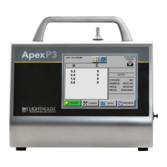
Press in on the rear power switch. Please contact While booting, the unit displays a startup "splash" screen. Lighthouse at 1-800-945- 5905 (USA Toll Free) or 1- The MAIN screen displays. 541-770-5905 (Outside of USA) for more information. -
Page 32: Touch Screen Overview
Lighthouse ApexPortable Operating Manual 10. If the instrument has been programmed with a delay before starting the pump, it displays, “DELAY”. 11. If the instrument is in AUTO mode with cycles and a hold time, “HOLDING” will display after each cycle and “FINISHED” will display when all the cycles are complete. -
Page 33: Main Screen
Operate the ApexPortable MAIN Screen The MAIN screen provides a snapshot view of the status of the instrument. The instrument can be powered by AC power or the internal battery. When the instrument is using battery power, the battery indicator will show the approximate level and percentage of the battery charge remaining as shown in Figure 5-2. - Page 34 Lighthouse ApexPortable Operating Manual • RECIPE button: Allows the user to view, load and unload recipes that have been configured and saved in the recipe data base via an Abbreviated Receipe Screen. To edit the recipe or to add or delete recipes, use CONFIG, which can be password-protected, from the MAIN screen (see Figure 5-47).
- Page 35 • Service Indicator: Indicates that the instrument may be in need of service. If wrench displays, please contact a Lighthouse authorized Service Provider at 1-800-945-5905 (USA Toll Free) or 1-541-770- 5905 (Outside of USA) for assistance or send an email to techsupport@golighthouse.com.
-
Page 36: Select Location
Acknowledge the popup by pressing the OK button to try to return to normal operation. If the error condition persists, contact Lighthouse support. Counting State Figure 5-5 Three Counting States... -
Page 37: Locations In Auto Mode
Operate the ApexPortable Note: • The blue highlight indicates which location is currently selected. Also see Figure 5- 54 for more information on • Use the UP and DOWN arrows to highlight a location. The arrows Locations. will move pages up and down. Press on the location name desired to select the location. -
Page 38: Viewing Two Columns Of Data
Lighthouse ApexPortable Operating Manual In the Zoomed Data View, functions can be enabled using the buttons on the right side bar of Figure 5-7. Figure 5-8 shows examples and explanations of the buttons. START or STOP counting Display Cumulative / Differential data... - Page 39 Operate the ApexPortable Press the “Diff+Cuml Zoom” button as shown in Figure 5-9, right frame, to enable the feature. This will display both differential and cumulative data on the Zoomed View screen as shown in Figure 5-10. DIFF CUML Data Data Figure 5-10 Differential and Cumulative Data in Zoomed View The buttons available after selecting Diff+Cuml Zoom are shown in...
-
Page 40: Config (Configuration) Screen
Lighthouse ApexPortable Operating Manual Go to the Settings screen and press Differential or Cumulative for the data type. See Figure 5-12. Figure 5-12 Settings Screen CONFIG Press CONFIG on the MAIN screen to display the Configuration (Configuration) screen as shown in Figure 5-13. This feature can be password- Screen protected. -
Page 41: Data Setup
Operate the ApexPortable DATA SETUP Figure 5-14 shows the Data Setup option buttons. These options allow the user to configure the parameters for data collection. Figure 5-14 Data Setup Options PARTICLE The instrument’s particle channels can be enabled or disabled on the Particle screen. -
Page 42: Sample
Lighthouse ApexPortable Operating Manual SAMPLE The SAMPLE screen configures the number of cycles, count times and volumes during a sample run. See Figure 5-16. Figure 5-16 Sample Timing Configuration Screen • CYCLES: The number of cycles is set to determine how many times the instrument samples the air in a single location. - Page 43 Operate the ApexPortable Note: • SAMPLE: The Sample Time (hh:mm:ss) is the duration of one The maximum counting cycle. The Sample Time will count down on the MAIN Sample Time is 23:59:59. screen when the instrument is in Auto or Manual mode to indicate how much time is remaining in the Sample.
-
Page 44: Setting
Lighthouse ApexPortable Operating Manual SETTING The Settings screen allows the user to configure the instrument to count in different modes and formats when running a sample. See Figure 5- Figure 5-18 Sample Settings Screen Count MODEs Count modes available are Auto, Manual, Beep and Concentration. -
Page 45: Format
Operate the ApexPortable Note: • The data will be recorded based on the set sample and hold times If BEEP mode is and can be viewed in the View Buffer and on the printouts. There set to one count, each beep may not be for every will be no indication on the record that the data was saved while the single count. -
Page 46: Alarm
Lighthouse ApexPortable Operating Manual ALARM Press ALARM button to open the Particle Alarm screen shown in Figure 5-19 to enable alarming on specific channels. Disable Enable press button to Press button to Change State change the alarm threshold Figure 5-19 Particle Alarm Configuration Example... -
Page 47: Clear
Operate the ApexPortable Press BACK to return to the CONFIG screen or press MAIN to return to the MAIN screen. The alarm activated channels will display a selection cursor (>) as shown in Figure 5-21. Note: Alarms are triggered per sample record. -
Page 48: Device Setup
Lighthouse ApexPortable Operating Manual data. DEVICE The DEVICE SETUP buttons adjust how the instrument operates when SETUP running samples. Specific functions for display options, data output and security can be enabled or disabled . See Figure 5-24. Figure 5-24 Device Setup Options CLOCK The Date &... - Page 49 Operate the ApexPortable Note: Press the M / D/ Y button to display the date as month-first. Pressing MONTH 1ST (M / D/ Y) is the default date format. D / M/ Y button displays the date as day-first and the Y / M/ D button displays the date as year-first.
-
Page 50: Options
Lighthouse ApexPortable Operating Manual OPTIONS The Options screen allows the user to make visual and sound adjustments as well as selecting different language formats and start-up functions. See Figure 5-29. Figure 5-29 Options Configuration Screen Contrast Adjust Adjust the contrast/brightness of the LCD screen by pressing the upper UP and DOWN arrows. - Page 51 Operate the ApexPortable WARNING: • The screen in Figure 5-30 appears. Touch anywhere on the screen to continue calibration. careful to touch the screen at the specified locations, only. Touching the screen elsewhere during this process will align the screen Performing touch incorrectly.
-
Page 52: Autostart Mode
Lighthouse ApexPortable Operating Manual touch the center circle to continue the alignment process. Press & Release Press & Release on the filled on the filled circle. circle. Figure 5-32 Fourth and Fifth Calibration Screens • Figure 5-32 shows the final alignment screen. Touching the filled circles properly completes the alignment process. -
Page 53: One Channel
Operate the ApexPortable One Channel If One Channel is enabled, only the first channel will be displayed on the MAIN screen. Note: One Channel mode only affects how data is displayed on the MAIN If the first channel screen. When the instrument is in One Channel mode, data will is disabled, the display and zoomed data view will be continue to be recorded, printed and downloaded for all channels. -
Page 54: Language
Lighthouse ApexPortable Operating Manual Language Press the LANGUAGE button to change the operating language as shown in Figure 5-35. Figure 5-35 Operating Language Screen Press the button next to the desired language to change it from the to the to enable. Press BACK to return to OPTIONS or MAIN button to return to MAIN screen. - Page 55 Operate the ApexPortable identifies it. The communication speed must be matched to the requirements of the network to which it will be connected or the connection will fail. Press the button describing the setting desired to be changed, such as ADDRESS, BAUD, etc. Figure 5-37 COMM Serial Settings Screen Management programs like LMS Express/RT will search for the instrument by the COMM Address specified on the screen shown in...
-
Page 56: Set Ethernet Settings
Lighthouse ApexPortable Operating Manual Set ETHERNET Settings Press COMM at the Config screen to display Figure 5-39. Press the ETHERNET’s toggle button to change it to the green check as shown. Figure 5-39 Comm ETHERNET Mode Press the ETHERNET button to open the COMM Ethernet Settings screen, Figure 5-40, which is displaying the original default values. -
Page 57: Output
Typical Ethernet settings for most networks and the ApexPortable a static IP, SUBNET empty/zeroes, and default Gateway is empty. Lighthouse recommends using a static IP adress. . OUTPUT The Output Setup screens (Figure 5-42) provide formatting and other options for printing to the optional USB printer or saving the data to a USB flash drive. -
Page 58: Usb Output
Separated-Value, a spreadsheet compatible format - this is the MAC before use. default setting displayed for the user; • *.LSD - Lighthouse Secure Data format is used and can be downloaded only by LMS Express, LMS Pro or LMS Pharma. 5-28 248083440-1 Rev 5... -
Page 59: Security
Operate the ApexPortable Output on Sample and Output on Alarm can be chosen together or separately, which is the preferred choice. Either *.CSV or *.LSD must be chosen, but not both simultaneously. If neither *.CSV nor *.LSD is chosen, *.CSV will be the default and will not leave screen until it is set. -
Page 60: Service
Press BACK to return to the CONFIG screen or press MAIN to return to the MAIN screen. Service This section of the Configuration screen is reserved for Lighthouse Authorized Service Providers only. The correct service password must be entered to access this area. -
Page 61: Recipe
Operate the ApexPortable RECIPE From the MAIN screen, press the small Recipe button to go into an "abbreviated" menu (shown in Figure 5-47). This allows users the convenience to access recipes without going into the CONFIG screen or requiring a password unlock to view, load and unload a recipe. Figure 5-47 MAIN Screen Abbreviated Recipe Screen To edit, add or delete recipes, though, one must press the Recipe button from the CONFIG screen to display the full Recipe setup screen. - Page 62 Lighthouse ApexPortable Operating Manual If a recipe already exists, the VIEW button will display the settings for it. See Figure 5-49 and Figure 5-50. The examples shown are for USB VIEW output with CSV file format. Figure 5-49 Recipe - Channel Settings...
- Page 63 Operate the ApexPortable To add the recipe to the database, press ENTER. The recipe CONFIG screen is then displayed as shown in Figure 5-52. Recipe Option Choose one to go to one of the screens shown in Figure 5-53. Figure 5-52 Recipe Configuration Press the option/function buttons shown in Figure 5-52 to open the feature’s corresponding screen shown in Figure 5-53.
-
Page 64: Location
Lighthouse ApexPortable Operating Manual LOCATION allows up to 200 different locations and associated ApexPortable alphanumeric labels. Press the LOC button on the CONFIG screen to display the Select Location screen as shown in Figure 5-54. Figure 5-54 LOCATION Setup Screen... - Page 65 Operate the ApexPortable • If a recipe is loaded and a location is selected that is not associated with a recipe, the user is prompted to unload the current recipe. If the user chooses to keep the loaded recipe, the location will adopt the current recipe settings.
-
Page 66: Remote Operation
Express RT, LMS Net, LMS Professional and LMS Pharma. Remote data retrieval via these products is easy and can be automated with warning levels and alerts programmed to notify specific users or other facilities. Visit www.golighthouse.com or contact Lighthouse Sales for additional information and details. Data View Data stored on the instrument is viewed in the Data View Buffer. - Page 67 Operate the ApexPortable Press the DATA button on the MAIN screen to display the Data View Buffer. DATA Depending on the sample setting configuration, the data displays in either RAW data mode as shown in Figure 5-58 or NORMALIZED to or m as shown in Figure 5-59.
- Page 68 Laser: Service. If SRVC appears, printouts will say “Service Required”; the sensor may need cleaning or repair. Please contact Lighthouse Technical Support at 1-800-945-5905 (USA Toll Free) or 1-541-770-5905 (Outside of USA).
-
Page 69: Output Data
Operate the ApexPortable Output Data Output Data to USB Printer Figure 5-60 USB Printer Attached From the MAIN screen, press the PRINT button (shown in Figure 5-60); the printer will print the record shown on the display, example contents shown in Figure 5-61. Formatting of the printout is based on the settings established via the Printer OUTPUT screen settings. - Page 70 Lighthouse ApexPortable Operating Manual From the MAIN screen, press the DATA button and display the desired "start" record by using the UP and DOWN arrows to move the list. Note the ending record desired. Press the Range button to display the # of Records screen to select a range of records to output.
- Page 71 Operate the ApexPortable Both file types supply the same data except for Status, which applies only to LSD format; the files contain the following information: • Model Name: • Serial Number: • Flow Rate: • Data Records including: • Sample Date / Time Stamp •...
-
Page 72: Report Requirements
Lighthouse ApexPortable Operating Manual Report Requirements Fed Std ft This report requires a minimum of 2 locations be measured, at least 1 sample be taken per location and at least 5 samples total be taken in each cleanroom at a minimum sample volume of 0.1 cubic feet. -
Page 73: Report Feature
Operate the ApexPortable REPORT FEATURE Enable the Report Feature by pressing the (Default setting) located at the top left of the screen. The check mark indicates the feature is enabled, which enables the PRINT MODE status on MAIN screen. See Figure 5-65 and 5-66. Note: If the user sets the Apex for a minimum volume,... -
Page 74: Set Up Report Room Parameters
Lighthouse ApexPortable Operating Manual • If Auto Increment is enabled, the user will be prompted to move the particle counter to the next assigned location after the current location’s number of cycles are completed. • After all of the required samples have been completed, the instrument will prompt the user to Save the Report Session as shown in Figure 5-67. - Page 75 Operate the ApexPortable • Use the Report Setup screen as shown in Figure 5-69. Figure 5-69 Report Setup Screen • Press the CLASS button and the Select Class screen displays as shown in Figure 5-70. Touch the desired class so it becomes highlighted.
- Page 76 Lighthouse ApexPortable Operating Manual Note: • Press the BACK button then the AREA button to display the Area If the entered Area Set Up screen shown in Figure 5-71. values needs more locations than available, a “Not enough locations” message will be displayed and the user will be asked to enter a lesser area.
- Page 77 Operate the ApexPortable • Press the FLOW button to display screen shown in Figure 5-73. Figure 5-73 Reports Air Flow Set Up Screen • Choose the appropriate type of air flow (Unidirectional, Non- Unidirectional), then press the BACK button to return to the SETUP screen, which will display the values that were configured so far.
- Page 78 Lighthouse ApexPortable Operating Manual • Press the BACK button then the SETTING button to format the instrument for CUML/DIFF, RAW/NORM, ft as shown in Figure 5-76. Figure 5-76 Reports Set Up Screen • Press BACK then LOC to select, add or delete locations or enable AUTO INC as shown in Figure 5-77.
-
Page 79: Set Up Counter To Run Reports
Operate the ApexPortable • When "REPORT" is enabled, the "LOC" and "SAVE" buttons are displayed only when there are at least the minimum number of locations needed for the recipe area available. • If REPORT is not active or the number of locations do not meet the minimum needed in setup, the LOC and SAVE buttons are not displayed. - Page 80 Lighthouse ApexPortable Operating Manual Note: The Minimum Volumes are measured in the Minimum Volume per Channel Size standard measurement Table 5-1 required by each specific report. Ch Size (μ) Min Vol (ft The number of digits allowed 0.100 for area to calculate volume is limited to a 5 digit value for ft2 0.200...
-
Page 81: Save Report
Operate the ApexPortable • Continue to move the to each location so it may run ApexPortable the necessary samples, responding ’YES’ to the move prompts and pressing START to sample at new locations. • After the instrument finishes recording at the last location, the instrument is ready to print the report. -
Page 82: Generate A Report From Data
Lighthouse ApexPortable Operating Manual Data and settings cannot be changed via the instrument web page. The must be set up using the Ethernet interface and correct ApexPortable IP for the network in which it is installed. Serial-configured (RS485 LAN) instruments do not support the web page feature. - Page 83 Operate the ApexPortable Choose the record (for a single record print) or records by using the RANGE button to select the records to be printed. Figure 5-86 Entering Records Screen Press the SAVE button to save the Report. Label it so its configuration is easily understood.
-
Page 84: Printing A Previously Printed Report
Lighthouse ApexPortable Operating Manual Press the REPORT button. 10. Choose the Report name just saved and press PRINT. Figure 5-89 Reports Screen, New Report Showing 11. If no USB printer is attached, the will report "NO ApexPortable USB". Printing a Previously Printed Report... -
Page 85: Web Reports Interface
Operate the ApexPortable Web Reports Interface has a Web Server that allows the user to view its ApexPortable data in real time and print reports from the web page’s Reports tab (see Figure 5-91 through 5-93). The instrument must be set up on an Ethernet LAN to have this feature work. -
Page 86: Web Page Reports
Lighthouse ApexPortable Operating Manual Web Page Reports Examples of passed and failed reports available via the ’s Web interface are shown in Figure 5-94 and Figure 5- ApexPortable Figure 5-94 Passed Report Sample 5-56 248083440-1 Rev 5... - Page 87 Operate the ApexPortable Figure 5-95 Failed Report Sample 248083440-1 Rev 5 5-57...
-
Page 88: Sample Printouts Of Standard Reports
Lighthouse ApexPortable Operating Manual Sample Printouts of Standard Reports Figure 5-96, Figure 5-97 and Figure 5-98 are examples of a Federal Standard Ft3, ISO 14644-1 and EU GMP 2009 reports. Note: If a recipe is loaded, the name of the... - Page 89 Operate the ApexPortable Note: If a recipe is loaded, the name of the ************* report session will be ISO 14644-1:2015 printed on the report. ApexP3 Serial#: 1512105005 Targeted Class: 8 Room Area: 1.49 m^2 Room Stat: Operational Air Flow: Unidirect Min Loc: 2 Min Samples/Room: 2 Recipe: ISO TEST...
- Page 90 Lighthouse ApexPortable Operating Manual Note: If a recipe is loaded, the name of the ************ report session will be printed on the report. EU GMP 2009 ApexP3 Serial #: 1412105005 Targeted Class: Room Area: 9.00 m^2 Room Stat: Operational Air Flow: Unidirect...
-
Page 91: Power Shutdown Levels
Operate the ApexPortable Power When the instrument is powered only by its rechargeable battery, a Shutdown Power Shutdown feature protects the battery from discharging completely. A complete discharge can damage the battery. It is not Levels recommended to allow the battery to discharge completely. The battery levels are displayed in Table 5-2. - Page 92 Operate the ApexPortable 248083440-1 Rev 5 5-62...
-
Page 93: Chapter 6 Maintenance Procedures
Maintenance Calibration To maintain optimum performance of this instrument, it should be recalibrated annually by a Lighthouse Authorized Service Provider. Zero Count This section provides the user with the particle counter zero count test Test procedure. A purge filter must be attached to the instrument and four (4) five (5) minute samples must be taken. -
Page 94: Fault Isolation
If more than one count is reported during the four five-minute samples, allow the instrument to sample for 30 minutes to purge it then repeat the test. If the second run fails, contact Lighthouse support. 10. After the instrument has met the requirements of the Zero Count test, return the instrument to its normal location and operating status. -
Page 95: Chapter 7 Program With The Modbus Protocol
Program with the MODBUS Protocol General Info family of instruments can be programmed using ApexPortable the MODBUS Protocol. The full protocol, as used, is detailed in Appendix A: “ApexPortable MODBUS Register Map v1.50” on page A-1. This chapter contains the information needed to program the basic configuration for the instrument using the MODBUS protocol. -
Page 96: Automatic Counting Mode
Lighthouse ApexPortable Operating Manual Table 7-1 Action Commands Value Action Saves all writable 4xxxx register values to the EEPROM. Clears the Data Buffer. Record count is set to zero. Saves the instrument parameters in the 40xxx registers to the EEPROM. Parameters include Sample Time, Hold Time, and Location. -
Page 97: Setting The Real Time Clock
Program with the MODBUS Protocol Configuring Setting the Real Time Clock with the The Real Time Clock (RTC) can be read in registers 40027 and 40028 MODBUS as shown in Table 7-2. Protocol Register 40027 is the high word for the real time clock; 40028 is the low word. -
Page 98: Changing The Default Instrument Parameters
Lighthouse ApexPortable Operating Manual Changing the Default Instrument Parameters The main instrument parameters involved with the operation of the are Location, Sample Time and Hold Time. See Table ApexPortable 7-4. Sample Time and Hold Time both use 2 registers, a high word and a low word. -
Page 99: Location (Register 40026)
Program with the MODBUS Protocol Location (Register 40026) For Particle Counters, this value specifies the location where a sample was recorded. Hold Time (Registers 40031, 40032) The Hold Time is used for pausing in between samples for multiple cycles. This time is specified in seconds. The maximum value is 359,999 seconds (high word: 5, low word: 32319) which is 99 hours, 59 minutes, and 59 seconds. -
Page 100: Alarm Enable Registers
Lighthouse ApexPortable Operating Manual Alarm and Alarm Enable Registers Threshold The Alarm Enable input registers (43xxx series) shown in Table 7-5 are Registers read/write. All enable data items are 4 bytes long and are stored across 2 registers. Byte and word ordering is big-endian. Thus, data items are formed by placing the high bytes in front of the low bytes. -
Page 101: Enable Alarming For A Channel
Program with the MODBUS Protocol Table 7-6 Alarm Enable Registers Register Data Type Description 43013 unsigned int Alarm Enable for Particle Channel 3 [high] 43014 unsigned int Alarm Enable for Particle Channel 3 [low] 43015 unsigned int Alarm Enable for Particle Channel 4 [high] 43016 unsigned int Alarm Enable for Particle Channel 4 [low]... -
Page 102: Setting The Alarm Threshold Value
Lighthouse ApexPortable Operating Manual The Data Status flag is set if any of the channels have a threshold exceeded state as true. Note: The threshold registers (45xxx series) shown in Table 7-8, run in comes parallel with the data registers (30xxx series). For example, data... -
Page 103: Appendix A Apexportable Modbus Register Map V1.50
ApexPortable MODBUS Register Map v1.50 COMM Lighthouse particle counters with MODBUS use the following Settings communications settings: Table A-1 MODBUS Communications Settings Baud Rate 19200 Data Bits Stop Bits Parity None Hardware Protocol RS232 or RS485 standard Software Protocol MODBUS ASCII (supports upper/lower case) -
Page 104: Sensor Settings Registers
Lighthouse ApexPortable Operating Manual Register Map Sensor Settings Registers Instrument settings are stored in holding registers (the 40xxx series), which are mostly read/writable. Not all holding registers are writable. Table A-3 describes the content of these registers. Table A-3 Sensor Settings Registers... - Page 105 ApexPortable MODBUS Register Map v1.50 Table A-3 Sensor Settings Registers Register Data Type Description 40021 ASCII string Model Name char[12], char [13] 40022 ASCII string Model Name char[14], char [15] 40023 unsigned integer Flow Rate. See registers 40041-40042 for flow rate units. Liquid Particle Counters and Samplers: Value equals flow rate.
- Page 106 Lighthouse ApexPortable Operating Manual Table A-3 Sensor Settings Registers Register Data Type Description 40035 unsigned integer Data Set [high]. Works in conjunction with 40036. Updates the instrument’s real time clock. Setting is the number of seconds since midnight, 1/1/1970. This number can be generated by the ANSI C/C++ time() function.
-
Page 107: Device Status
ApexPortable MODBUS Register Map v1.50 Table A-3 Sensor Settings Registers Register Data Type Description 40065 signed integer Run-time particle channel alarm low flags (bit 0 = channel 1, …). 40074 signed integer ApexPortable: Last Calibration Date [high]. Indicates when instrument was last calibrated. - Page 108 Lighthouse ApexPortable Operating Manual Table A-4 Current Device Status (40003/40057) Description ApexPortable: FLOW STATUS: Set to 1 when unit’s flow is out of spec, else set to 0. ApexPortable: SERVICE STATUS: Set to 1 when unit needs to be serviced, else set to 0.
- Page 109 ApexPortable MODBUS Register Map v1.50 Table A-5 Additional Device Status (40056) Description ApexPortable: BACKGROUND STATUS: Set to 1 when unit’s pho- toamp background is out of spec, else set to 0 ApexPortable: PHOTODIODE STATUS: Set to 1 when photodiode has failed, else set to 0 ApexPortable: CALIBRATION DUE DATE STATUS: Set to 1 when unit is past calibration due date, else set to 0...
-
Page 110: Alarm Enable Registers
Lighthouse ApexPortable Operating Manual Table A-6 Command Register Value Action Set Real Time Clock. Writes "Data Set" values (from Registers 40035 & 40036) to the local Real Time Clock. New time value is saved. Alarm and Alarm Enable Registers Threshold The Alarm Enable input registers (43xxx series) are read/write. -
Page 111: Enable Alarming For A Channel
ApexPortable MODBUS Register Map v1.50 Table A-8 Alarm Enable Registers Register Data Type Description 43010 unsigned int Alarm Enable for Particle Channel 1 [low] 43011 unsigned int Alarm Enable for Particle Channel 2 [high] 43012 unsigned int Alarm Enable for Particle Channel 2 [low] 43013 unsigned int Alarm Enable for Particle Channel 3 [high]... -
Page 112: Setting The Alarm Threshold Value
Lighthouse ApexPortable Operating Manual example: <High Bytes><Low Bytes> = <4 Byte Data Item> For particle channels, the threshold value is a 32-bit unsigned integer. If the data value exceeds the threshold value and the alarm is enabled for that channel, the threshold flag in the Data Status register (30007- 30008, bit 4) is set. -
Page 113: Data Registers
ApexPortable MODBUS Register Map v1.50 Table A-11 Alarm Threshold Registers set to 1000 Particle Threshold Registers Channel Value 45013 - 45014 1000 45015 - 45016 1000 Data Data is stored in the input registers (30xxx series), which are read-only. Registers All data items are four bytes long and are stored across two registers. - Page 114 Lighthouse ApexPortable Operating Manual Table A-12 Data Registers Register Data Type Description 30009 unsigned integer Particle Channel 1 [high] 30010 unsigned integer Particle Channel 1 [low] 30011 unsigned integer Particle Channel 2 [high] 30012 unsigned integer Particle Channel 2 [low]...
- Page 115 ApexPortable MODBUS Register Map v1.50 Table A-13: Instrument Current Status Value Action Instrument Service Status 0 = Instrument is working correctly. 1 = Service light is on. Instrument malfunction detected. Threshold High Status 0 = Threshold not exceeded. 1 = Threshold exceeded Threshold Low Status 0 = Threshold not exceeded.
-
Page 116: Device Status Word
Lighthouse ApexPortable Operating Manual Table A-13: Instrument Current Status Value Action ApexPortable: Photodiode health status 0 = Photodiode good. 1 = Photodiode failure ApexPortable: Calibration due date status 0 = Unit has not passed calibration date. 1 = Unit has passed calibration. -
Page 117: Data Enable Registers
ApexPortable MODBUS Register Map v1.50 Data Enable Registers Note: The 31xxx register series is used to determine which data items in All data records have the same enable 30xxx are enabled. Enabled items contain recorded data. Data states. The user does not retrieved from disabled items return garbage. -
Page 118: Data Units Registers
Lighthouse ApexPortable Operating Manual Table A-15 Data Type Registers String Description AIRV Air Velocity DPRS Differential Pressure Electrostatic Discharge FLOW Flow Rate LASV LASER Voltage VOLT Voltage PRES Pressure CURR Current LASV LASER Current LASP LASER Power Note: Particle data items are typed specially. They contain numbers,... - Page 119 ApexPortable MODBUS Register Map v1.50 rest of the string is padded with NULLs. Note that a Units string using all 4 characters does not end with a NULL. Note: The Table A-17 shows units that may be sent by the device. Some are Be aware that LWS Particle Counters not currently used but are reserved for future use.
- Page 120 Lighthouse ApexPortable Operating Manual A-18 248083440-1 Rev 5...
-
Page 121: Appendix B Limited Warranty
Upon expiration of the initial two-year warranty, all parts and the warranty is null and void. This warranty is limited to a period repairs completed by an authorized Lighthouse repair technician of two years, except as noted below, without regard to whether are subject to a six (6) month warranty. - Page 122 Lighthouse ApexPortable Operating Manual 248083440-1 Rev 5...
- Page 123 Index Charging Indicators 5-4 Class 1 LASER 1-1 Class Level 5-45, 5-49 Abbreviated Location Screen 5-3 Clear Buffer 5-17 Abbreviated Receipe Screen 5-4 Clear the Data Buffer 7-2 AC Indicator 5-3 Clock 5-18 AC Operation Icons 5-4 COMM Address 5-24 Accessories 2-2 Command Register A-7 Additional help i-i...
- Page 124 Lighthouse ApexPortable Operating Manual Configuration Screen 5-10 Data Setup 5-10 Device Setup 5-10 Enable Alarming 7-7, A-9 Contrast Adjust 5-20 Enclosure 2-3, 2-4 Count Mode 5-14 EU GMP 5-42 Auto 5-14 External Connections 2-3, 2-4 Concentration 5-15 Manual 5-14 Counting Efficiency 2-3, 2-4...
- Page 125 Index Light Source 2-3, 2-4 Mode 5-5 Limits Auto 5-5 Maximum tubing length to ISO Probe 2-3, Beep 5-5 Concentration 5-5 LMS Software Remote features 4-3 Manual 5-5 Location 5-3, 5-29, 7-5 + / - buttons 5-4 Changing in Auto Mode 5-7 Select 5-3 Normalized 5-15 Location Setup 5-34...
- Page 126 Lighthouse ApexPortable Operating Manual Using Sensor Setting Registers 7-4 Service 5-30 Service Indicator 5-5 Raw 5-15 Setting the Alarm Threshold Value 7-8, A-10 Real Time Clock Setting the Real Time Clock 7-3 Setting 7-3 single record printing 5-53 Realtime output 5-23...
- Page 127 Index Warning Electrostatic Discharge 1-3 Port-Connect 1-3 Warnings Port-Connect 1-3 Web Reports Interface 5-55 Weight 2-3, 2-4 Zero Count Check Troubleshooting 6-2 Zero Count Level 2-3, 2-4 Zero Count Test 6-1 Zoomed Data View 5-7 248083440-1 Rev 5...
- Page 128 Lighthouse ApexPortable Operating Manual 248083440-1 Rev 5...
- Page 130 Service and Support Tel. 1-800-945-5905 (USA Toll Free) Tel. 1-541-770-5905 (Outside of USA) techsupport@golighthouse.com www.golighthouse.com...
Need help?
Do you have a question about the ApexPortable Series and is the answer not in the manual?
Questions and answers