Table of Contents
Advertisement
Advertisement
Table of Contents
Troubleshooting

Related Manuals for Fellow Kogyo FOCAS-2000

Summary of Contents for Fellow Kogyo FOCAS-2000
- Page 1 15ppm Bilge Alarm FOCAS-2000 Oil Concentration Detector Instruction Manual Read this instruction manual thoroughly before use to operate the product safely by following precautions. Be sure to keep it in an easy-to-access place so as to refer to it whenever necessary.
-
Page 2: Table Of Contents
Page. 1 Contents General Introduction 1-1. ・・・・・・・・・・・・・・・・・・・・・・・・・・・・・・・ page. 2 Product Features 1-2. ・・・・・・・・・・・・・・・・・・・・・・・・・・・ page. 2 Safety precautions ・・・・・・・・・・・・・・・・・・・・・・・・・・・ page. 3 1-3. Specifications Product Specification ・・・・・・・・・・・・・・・・・・・・・・・・・ page. 3 2-1. External dimensions and component names ・・・・・・・・・ page. 4 2-2. Internal layout figure and terminal block ・・・・・・・・・・・・・ page. 5 2-3. -
Page 3: Product Features ・・・・・・・・・・・・・・・・・・・・・・・・・・・ Page
In addition, never break the equipment seal, as such an act is deemed as fraudulent. 3. This equipment is warranted for one year after delivery. In case any failure responsible to Fellow Kogyo is experienced during the period, the pertaining part or component shall promptly be replaced or repaired. -
Page 4: Safety Precautions ・・・・・・・・・・・・・・・・・・・・・・・・・・・ Page
(FOCAS-1800). If used, its data will be lost. We cannot assure and recover any operational log data lost by the use in the existing oil concentration detector. By the way, FOCAS-2000 can read the operational log memory card of FOCAS-1800. -
Page 5: External Dimensions And Component Names ・・・・・・・・・ Page
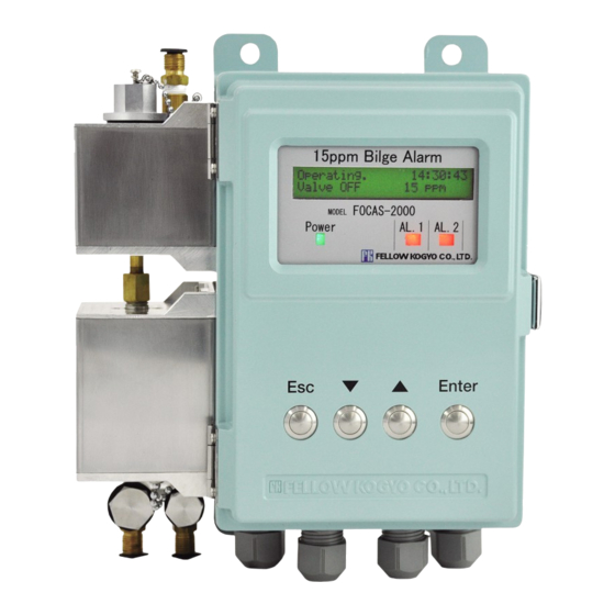
Earth screw (M4) Panel configuration Maximum Display 15ppm Bilge Alarm LCD display Display MODEL FOCAS-2000 POWER Green lamp lights when applying current. POWER AL. 1 AL. 2 AL. 1 Red lamp blinks when oil alarm is activated or Alarm2 lamp (red) Power lamp the unit is defective. -
Page 6: Internal Layout Figure And Terminal Block ・・・・・・・・・・・・・ Page
Specifications Internal layout figure and terminal block ■ 2-3. 2-3-1 Inside component layout of FOCAS-2000 Memory card for FOCAS-2000 white or black with marking (circle painted all red) Desiccant (silica gel) For replacement of the desiccant, see ● Operation record memory "8-6 Checkup and replacement timing... -
Page 7: Relay Contact Output, Alarm Lamp Movement View ・・・・・ Page
Page. 6 Specifications Relay contact output, alarm lamp movement view ■ 2-4. -
Page 8: Precautions For Piping Work ・・・・・・・・・・・・・・・・・・・・・ Page
Page. 7 Connecting pipes Mounting space 3-1. 150 more than 116 1.0 Installation 4- 10 Set up this unit vertically 4-M8 Fix 4 setup holes with volt firmly Use only bolts. A distance of at least 210 mm is required on the left. 85 more than 300 more than This amount is required for replacing the sensor unit or solenoid valve unit. -
Page 9: About Items Displayed On The Screen
Page. 8 Preparing for Operation About items displayed on the screen 4-1. Standby state State Display item Description Current state: standby state The oil concentration detector enters the Shows the current state and the current standby state when the pressure at the time when the oil concentration detector sample water inlet is lower than 0.03 is standing by. -
Page 10: Outline Of Operating Conditions ・・・・・・・・・・・・・・・・・・・ Page
Outline of operating conditions 4-2. The FOCAS-2000 oil concentration detector automatically starts to operate when detecting a water pressure of 0.03 MPa or more at the sample water inlet. After starting to run, the oil concentration detector waits for a preset time (warm-up time) until the sample water state becomes stable so as not to detect a residue in the area between the sample water pipeline and the detection tube. - Page 11 Page. 10 Preparing for Operation Set the clock right. A warning is displayed to indicate "Set the clock." Press "Enter." In this state, you can set the clock. Press "Enter" to set a year. The cursor blinks at a digit you can enter a value. Press "...
-
Page 12: Test-Operation Methiod By The Manual Operation Function ・・ Page
Page. 11 Operation Be sure to confirm the items below. Check and make sure the installation, piping, wiring, terminal base connection, and water pressure (0.03 MPa or higher at the sample water inlet) once more. If the sample water pressure of 0.03 MPa or higher cannot be obtained at the sample water inlet, you can perform simple test operation of the oil concentration detector. - Page 13 Page. 12 Operation Continued from the preceding page. (Manual test-operation procedure) When the alarm test starts, the oil concentration detector artificially increases the oil concentration to enable the alarm test. "sim" appears in the center of the top line of the screen. The ppm value "x"...
-
Page 14: Test-Operation Method By The Automatic Operation Function ・・・・・・ Page
Page. 13 Operation Test operation method by the Automatic operation function 5-2. Use the Automatic Operation to test-operation the oil concentration detector after installing and constructing it or in the following cases: when you want to operation the bilge pump and execute an alarm test including the three-way valve output signal. when a water pressure of 0.03 MPa or higher can be applied to the sample water inlet. -
Page 15: Function Of Judging Whether The Detection Tube Is Clean ・・ Page
Page. 14 Operation Function of judging whether the detection tube is clean 5-3. This function judges whether the detection tube is clean when the washing process ends after manual/auto operation. When the washed detection tube is not clean When it is judged the detection tube is not clean, "Warning: cell too dirty" is displayed on screen. When this message is displayed, manually wash the detection tube (see “8-2-1”), shut off the primary power supply and clean the sensor (with brush, see”8-4”). -
Page 16: Tabulated List Of Menu Items ・・・・・・・・・・・・・・・・・・・・ Page
Page. 15 Setting Tabulated list of menu items 6-1. -
Page 17: Time Correction Of The Clock ・・・・・・・・・・・・・・・・・・・・・ Page
Page. 16 Setting Various settings, testing function, operational log viewing and more can be done by using the operation switch. The switch is ineffective during operation. Ensure the status being in standby. During setting, automatic operation is disabled even if the pressure switch is set at the specified pressure (0.03 MPa) or higher. Time correction of the clock (Clock Adjustment) 6-2. -
Page 18: Various Settings ・・・・・・・・・・・・・・・・・・・・・・・・・・・・・ Page
Page. 17 Setting Various settings (Setting) 6-3. You can change settings according to your operating conditions. Keep on pressing "Esc" for 2 seconds or longer in the standby state to change settings. You cannot change settings in the Operation mode. Setting data and ranges 6-3-1. -
Page 20: Operation And Maintenance ・・・・・・・・・・・・・・・・・・・・・・・・ Page
Page. 19 7. Operation and Maintenance ● The FOCAS-2000 oil concentration detector is a high precision instrument. ● It is recommended for you to periodically check and maintain FOCAS-2000 as shown below to assure its performance fora long time. Requirements ■... -
Page 21: Testing Function
Page. 20 Maintenance and Checking Continued from the preceding page (8-1-1. Manual operation (Manual running)) ■ When "manual running" is selected. The left screen is displayed for about 5 seconds and the manual operation process starts. "Warming up" is displayed on the bottom line of the screen. The remaining time (in seconds) is displayed to the right of "Warming up."... - Page 22 Page. 21 Maintenance and Checking Zero-point check ExamZero ppm press Enter 8-1-2. Be sure to clean the sensor before starting the zero-point check. Always prepare mineral water. This may be caused by the dirty detection tube due to aging or contaminated water supplied from the fresh water inlet. This function is used to check such a stain of the detection tube.
- Page 23 Page. 22 Maintenance and Checking Zero-point check MeasureWater press Enter 8-1-3. This function simply checks the oil concentration of water supplied from the fresh water inlet. Execute manual washing to cleaning the sensor before starting this check function (Zero-point check by feeding water from the fresh water inlet).
- Page 24 Page. 23 Maintenance and Checking RECout output test Current Output xxmA 8-1-4. This test function is used to check the operation of a connected instrument and cable connections. This function can output a current of 0 to 24 mA at intervals of 1 mA. Keep on pressing "Esc"...
- Page 25 Lower row: Status of the freshwater valve; XXX OFF: Closed; XXX ON: Open 1, 2, 3 and 4 Level values for each sensor; Temp Sensor temperature Page 3 each sensor level and temperature value are checked while FOCAS-2000 is ※ measuring oil content in sample water or fresh water <Reference>...
-
Page 26: Maintenance ・・・・・・・・・・・・・・・・・・・・・・・・・・・・・・・ Page
Page. 25 Maintenance and Checking Maintenance (Maintenance Mode) 8-2. The oil concentration detector has Manual Washing, Zero-Point Compensation, Operation Check, and Reset After Zero-Point Compensation functions. (See "6. Setting (Outline) - Tabulated list of menu items.") To use a testing function, keep on pressing "Esc" for 2 seconds or longer in the standby state. (The testing function is not available while the oil concentration detector is running.) Select a maintenance function by operating "... - Page 27 Page. 26 Maintenance and Checking Zero-point compensation Zero Adjust press Enter 8-2-3. When a high oil concentration value is displayed after a Zero-point check using mineral water, this function is displayed oil concentration value (less than 5 ppm) to 0 ppm. Do not implement the Zero-Point Compensation function just after "Stain warning"...
- Page 28 Page. 27 Maintenance and Checking Zero-point compensation (Zero Adjust press Enter) 8-2-3. The zero-point compensation is disabled when oil concentration over 5 ppm is detected in the zero-point compensation after sensor cleaning because of oil or residue of contaminant in the detection tube. This example shows a case that an oil concentration over 5 ppm is detected.
-
Page 29: Viewing The Operational Log ・・・・・・・・・・・・・・・・・・・・・ Page
"Dump Log" as a viewing item is an optional function. (For more information, call your local Fellow Kogyo distributor or Sales Division of Fellow Kogyo.) This function can also view the content of operational log memory card of FOCAS-1800 (with some limitations). (see 1 of “section 6-1”... - Page 30 Page. 29 Page. 29 Maintenance and Checking Maintenance and Checking Outlined and detailed displays of the operational log Outlined and detailed displays of the operational log ■ 8-3-2. 8-3-2. ● Here we'll explain how to view details of the operational log from the outlined display and also explain their screens. Here we'll explain how to view details of the operational log from the outlined display and also explain their screens.
- Page 31 Page. 30 Maintenance and Checking Oil alarm point (Alarm Setting) record display screen 8-3-3. Here we'll explain display screens on which you can check oil alarm point set values. Display of a group item This display example explains how to view Hours : Minutes : Seconds the Alarm1 Setting operational log from the Code No.
-
Page 32: Cleaning The Sensor (Brush Washing) ・・・・・・・・・・・・・・ Page
Clean the detection tube once per 2 weeks or per 10 measurements whichever comes first. Be sure to turn off power to the oil concentration detector (FOCAS-2000) before starting sensor cleaning. Carefully clean the sensor unit and the inside of the detection tube. -
Page 33: Checkup And Replacement Timing Of
Page. 32 Maintenance and Checking Checkup and replacement timing of desiccant (silica gel) 8-6. ■ CAUTION ● Be sure to close the case cover and lock the snap latch before operation the oil concentration detector. Inspect the color of desiccant (silica gel)in the indicator every month. When desiccant (silica gel) is change in color, replace it by new one. -
Page 34: Replacing The Operational Log Memory Card ・・・・・・・・・ Page
(Do not push in the card too strong. The card may not be locked.) 《CAUTION》Please note one memory card should be used for only one FOCAS-2000 unit. If the memory card which was used in a certain FOCAS-2000 is inserted in another FOCAS-2000 unit, 『Warning[11E]Memory ID different』is displayed. -
Page 35: Troubleshooting ・・・・・・・・・・・・・・・・・・・・・・・・・・・・・・・・・・・ Page
LCD display screen counts up on the "Standby" screen. When the oil concentration detector cannot be recovered by the above operations, call your local Fellow Kogyo distributor or Sales Division of Fellow Kogyo. In the maintenance works below, power to the oil concentration detector must be shut off to prevent electric shocks and device failures. - Page 36 In the case "Warning" or "Error" is displayed on the LCD display screen ● To assure the performance, the oil concentration detector (FOCAS-2000) is so designed to stop running when detecting a warning or error state. In such a state, the AL1 and AL2 alarm lamp blink with a warning or error code on the LCD display screen.
-
Page 37: Troubleshooting
"2-3 Internal layout figure and terminal base." When the oil concentration detector cannot be recovered by the above operations, call your local Fellow Kogyo distributor or Sales Division of Fellow Kogyo. In the case the other data is displayed on the LCD display screen... -
Page 38: Service Parts ・ Option Parts ・・・・・・・・・・・・・・・・・・・・・・・・ Page
Request The FOCAS-2000 oil concentration detector is a high precision instrument capable of detecting oil in parts per million. To prevent the product against failures and maintain its accuracy, the product must be calibrated within 5 years by the manufacturer or the agent authorized by the manufacturer and have the IOPP certificate renewal examination. -
Page 39: Display Of Groups And Description Of Statuses ・・・・・・・・・・ Page
Page. 38 Display of groups and description of statuses. Display of groups and description of statuses. グループ表示とステータスの内容 Contents (at the time of Contents (at the time of Group Code No Code No indication occurrence) cancel release) コード コード 番号 内容(発生時) 番号... - Page 40 Display of groups and description of statuses. Group Contents (at the time Contents (at the time of Code No Code No indication of occurrence) cancel release) コード コード 内容(発生時) 内容(解除時) グループ表示 番号 番号 Difference over 5ppm ---- ------------------ Zero 点補正 5ppm 超え Zero adjust fail ---- ------------------...
Need help?
Do you have a question about the FOCAS-2000 and is the answer not in the manual?
Questions and answers