Midea Aqua Tempo Super II Series Service Manual
Commercial air conditioners
Hide thumbs
Also See for Aqua Tempo Super II Series:
- Technical & service manual (84 pages) ,
- Engineering data (101 pages)
Advertisement
Table of Contents
Advertisement
Chapters
Table of Contents

Related Manuals for Midea Aqua Tempo Super II Series


Summary of Contents for Midea Aqua Tempo Super II Series
- Page 1 Commercial Air Conditioners Service Manual...
- Page 2 Aqua Tempo Super II CONTENTS Part 1 General Information ................3 Part 2 Component Layout and Refrigerant Circuits ........5 Part 3 Control ....................15 Part 4 Diagnosis and Troubleshooting ............33 201709...
- Page 3 Aqua Tempo Super II 201709...
-
Page 4: Part 1 General Information
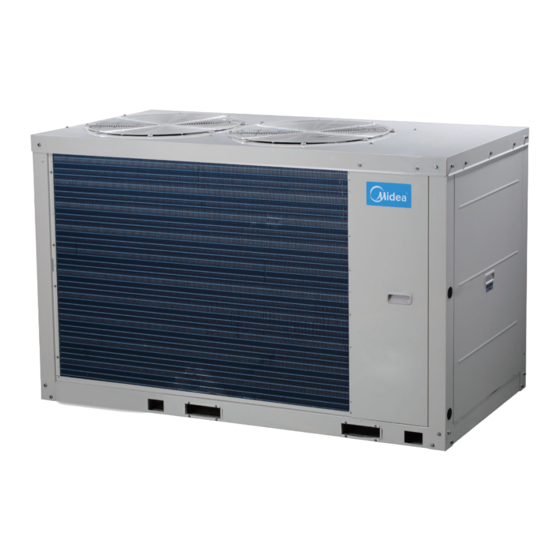
Aqua Tempo Super II Part 1 General Information 1 Unit Capacities and External Appearance ........... 4 2 Water outlet temperature range ..............4 201709... - Page 5 M-Thermal Mono 1 Unit Capacities and External Appearance Table 1-2.1: Aqua Tempo Super II unit capacity range and unit appearances Capacity 30kW 60kW Model MC-SU30-RN1L MC-SU30-RN1L Appearance Power supply 380-415V/3Ph/50Hz 2 Water outlet temperature range Table 1-2.1: Aqua Tempo Super II unit water outlet temperature range Mode Range °C...
-
Page 6: Part 2 Component Layout And Refrigerant Circuits
Aqua Tempo Super II Part 2 Component Layout and Refrigerant Circuits Layout of Functional Components ............6 Piping Diagrams ..................10 Refrigerant Flow Diagrams ..............13 201709... - Page 7 Aqua Tempo Super II 1 Layout of Functional Components MC-SU30-RN1L Figure 2-1.1: MC-SU30-RN1L front view Fan motor Wired controller Electric control box DC inverter compressor Accumulator Oil separator Figure 2-1.2: MC-SU30-RN1L rear view Water side heat exchanger Manual air purge valve Safety valve Water inlet pipe Water flow switch...
- Page 8 Aqua Tempo Super II Figure 2-1.3: MC-SU30-RN1L top view Accumulator Low pressure High pressure switch sensor Solenoid valve High pressure switch Discharge Four-way valve temperature switch Electronic expansion valve Low pressure High pressure gauge point gauge point 201709...
- Page 9 Aqua Tempo Super II MC-SU60-RN1L Figure 2-1.4: MC-SU60-RN1L front view Fan motor Electric control box DC inverter compressor Oil separator Figure 2-1.5: MC-SU60-RN1L rear view Safety valve Accumulator Water side Air purge valve heat exchanger Water inlet pipe Accumulator Water flow Manual water switch drain valve...
- Page 10 Aqua Tempo Super II Figure 2-1.6: MC-SU60-RN1L top view Low pressure switch High pressure Solenoid sensor valve SV4 High pressure switch Discharge temperature Four-way valve switch Electronic expansion valve Low pressure High pressure gauge point gauge point 201709...
- Page 11 Aqua Tempo Super II 2 Piping Diagrams MC-SU30-RN1L Figure 2-2.1: MC-SU30-RN1L piping diagram Tz/7 Taf2 Taf1 Legend Compressor Discharge temperature sensor 1 Low pressure switch Discharge temperature sensor 2 Discharge temperature control switch Air side heat exchanger refrigerant outlet temperature sensor High pressure switch Outdoor ambient temperature sensor Oil separator...
- Page 12 Aqua Tempo Super II MC-SU60-RN1L Figure 2-2.2: MC-SU60-RN1L piping diagram Capillary Taf2 Taf1 Legend Compressor Discharge temperature sensor 1 Low pressure switch Discharge temperature sensor 2 Discharge temperature control switch Air side heat exchanger refrigerant outlet temperature sensor High pressure switch Outdoor ambient temperature sensor Oil separator TZ/7...
- Page 13 Aqua Tempo Super II Key components: 1. Compressor Maintains pressure differential between high and low pressure sides of the refrigerant system. 2. Fan Ventilates the air side heat exchanger. 3. Oil separator: Separates oil from gas refrigerant pumped out of the compressor and quickly returns it to the compressor. Separation efficiency is up to 99%.
- Page 14 Aqua Tempo Super II 3 Refrigerant Flow Diagrams Heating operation Figure 2-3.1: Refrigerant flow during heating operation Cooling and defrosting operation Figure 2-3.2: Refrigerant flow during cooling and defrosting operations 201709...
- Page 15 Aqua Tempo Super II 201612...
-
Page 16: Table Of Contents
Aqua Tempo Super II Part 3 Control General Control Scheme Flowchart ............. 16 Stop Operation ..................17 Standby Control .................. 17 Startup Control ..................18 Normal Operation Control ..............20 Protection Control ................23 Special Control ..................29 Role of Temperature Sensors in Control Functions ....... 31 201709... -
Page 17: General Control Scheme Flowchart
Aqua Tempo Super II 1 General Control Scheme Flowchart Sections 3-2 to 3-7 on the following pages detail when each of the controls in the flowchart below is activated. Stop operation Abnormal shutdown System stops Standby control Crankcase heater control ... -
Page 18: Stop Operation
Aqua Tempo Super II 2 Stop Operation The stop operation occurs for one of the following reasons: 1. Abnormal shutdown: in order to protect the compressors, if an abnormal state occurs the system makes a 'stop with thermo off’ operation and an error code is displayed on the outdoor unit’s PCB digital displays and on the user interface. -
Page 19: Startup Control
Aqua Tempo Super II 4 Startup Control 4.1 Compressor Startup Delay Control In initial startup control and restart control (except in defrosting operation), compressor startup is delayed such that a minimum 7 minutes has elapsed since the compressor stopped, in order to prevent frequency compressor on/off and to equalize the pressure within the refrigerant system. - Page 20 Aqua Tempo Super II 4.3 Startup Control for Heating Operation Table 3-4.1: Component control during startup in heating mode Wiring diagram Component 30kW 60kW Control functions and states label Inverter compressor A COMP A Compressor startup program selected according to ●...
-
Page 21: Normal Operation Control
Aqua Tempo Super II 5 Normal Operation Control 5.1 Component Control during Normal Operation Table 3-5.1: Component control during heating operation Wiring diagram Component 30kW 60kW Control functions and states label Inverter compressor A COMP A ● ● Controlled according to load requirement Inverter compressor B COMP B ●... - Page 22 Aqua Tempo Super II 5.2 Compressor Output Control The compressor rotation speed is controlled according to the load requirement. Before compressor startup, the outdoor unit determines the compressor target speed according to outdoor ambient temperature, discharge temperature and then runs the appropriate compressor startup program. Refer to Part 3, 4.2 “Compressor Startup Program”. Once the startup program is complete, the compressor runs at the target rotation speed.
- Page 23 Aqua Tempo Super II superheat and compressor frequency, and uses the suction temperature, air side heater exchanger temperature, discharge temperature to modify the control. When the outdoor unit is in standby: The EXV is at position 352 (steps). ...
-
Page 24: Protection Control
Aqua Tempo Super II 6 Protection Control 6.1 High Pressure Protection Control This control protects the refrigerant system from abnormally high pressure and protects the compressor from transient spikes in pressure. Figure 3-6.1: High pressure protection control Normal operation > 4.4MPa <... - Page 25 Aqua Tempo Super II 6.4 Compressor and Inverter Module Protection Control This control protects the compressors from abnormally high currents and protects the inverter modules from abnormally high temperatures. It is performed for each compressor and inverter module. Figure 3-6.4: Compressor current protection control Normal operation Current >...
- Page 26 Aqua Tempo Super II 6.6 DC Fan Motor Protection Control This control protects the DC fan motors from abnormal power supply. DC fan motor protection occurs when the fan module does not receive any feedback from the fan motor. When DC fan motor protection control occurs the system displays the PU error code and the unit stops running. When PU protection occurs 2 times in 120 minutes, the FF error is displayed.
- Page 27 Aqua Tempo Super II 6.8 Air Side Heat Exchanger High Temperature Protection Control This control protects the air side heat exchanger from high temperature. Figure 3-6.9: Air side heat exchanger high temperature protection control 1 Normal operation T3 < 60°C T3 >...
- Page 28 Aqua Tempo Super II 6.10 Water Side Heat Exchanger Low Temperature Protection Control This control protects the water side heat exchanger from ice formation. Figure 3-6.12: Water side heat exchanger low temperature protection control in normal cooling mode Normal operation Min (Taf1 or Taf2) ≤...
- Page 29 Aqua Tempo Super II 6.11 Water Side Heat Exchanger Low Pressure Protection Control This control protects the water side heat exchanger from ice formation. Figure 3-6.14: Water side heat exchanger low pressure protection control in normal cooling mode Normal operation Pe <...
-
Page 30: Special Control
Aqua Tempo Super II 7 Special Control 7.1 Outdoor Unit Duty Cycling In systems with multiple outdoor units, outdoor unit duty cycling is used to balance the compressor running time. Outdoor unit duty cycling occurs whenever all the outdoor units stop running (either because the leaving water set temperature has been reached or because a master unit error has occurred): ... - Page 31 Aqua Tempo Super II Table 3-7.1: Component control during defrosting operation Wiring diagram Component 30kW 60kW Control functions and states label Inverter compressor A COMP A ● ● Runs at defrosting operation rotation speed Inverter compressor B COMP B ● DC fan motor A FAN A ●...
-
Page 32: Role Of Temperature Sensors In Control Functions
Aqua Tempo Super II 8 Role of Temperature Sensors in Control Functions Table 3-8.1: Names and functions of the temperature sensors Sensor Number Sensor name Mode Control functions code Crankcase heater control Electronic expansion valve control Heating Compressor output control ... - Page 33 Aqua Tempo Super II Compressor output control Heating Electric auxiliary heater control Total water outlet temperature sensor Compressor output control Cooling Water side heat exchanger anti-freeze protection control Compressor output control Heating Inverter module temperature protection Inverter module temperature sensor 1/ Inverter module ...
-
Page 34: Part 4 Diagnosis And Troubleshooting
Aqua Tempo Super II Part 4 Diagnosis and Troubleshooting Outdoor Unit Electric Control Box Layout ..........34 Outdoor Unit PCBs ................36 Error Code Table .................. 47 Troubleshooting .................. 49 Appendix to Part 5 ................95 201709... - Page 35 Aqua Tempo Super II 1 Outdoor Unit Electric Control Box Layout MC-SU30-RN1L Figure 4-1.1: Electric control box front view- top layer Main control board Wired controller Power supply terminal 3-way terminal Figure 4-1.2: Electric control box front view-bottom layer AC indicator A AC filter board Reactor Inverter module...
- Page 36 Aqua Tempo Super II MC-SU60-RN1L Figure 4-1.3: Electric control box front view-top layer AC filter board A Main control board Wired controller 3-way terminal Figure 4-1.4: Electric control box side view-bottom layer Three-phase bridge Inverter module A rectifier B Inverter module B Reactor A AC indicator A Three-phase...
- Page 37 Aqua Tempo Super II 2 Outdoor Unit PCBs 2.1 Types Aqua Tempo Super II units have four PCBs – main control board, three phase AC filter board, DC fan inverter module board and compressor inverter module board. In addition to the four PCBs, MC-SU30-RN1L model each has one board while MC-SU30-RN1L model have one main control board and the other boards each has two boards.
- Page 38 Aqua Tempo Super II Table 4-2.1:Outdoor unit main PCB Label in Figure Code Content Voltage 4-2.1 Pump 1 connection 0-220V AC(varying) CN30 Power sequence detection connection 380V DIP switches CN72 Power supply to user interface 9V DC ENC1 Unit capacity dial switch ENC3 Address dial switch DSP1...
- Page 39 Aqua Tempo Super II CN44 Water flow switch, additional control and Cool/heat connections 0 or 12V DC IC10 EEPROM CN21 Remote alarm connection On/off signal CN19_N Electric auxiliary heater N line connection On/off signal CN19_L Electric auxiliary heater N line connection On/off signal Pump 2 connection On/off signal...
- Page 40 Aqua Tempo Super II Anti-freezing protection: Pb and operating frequency flash alternately at 1s intervals Outdoor unit address Actual value = value displayed Outdoor unit capacity 0:30KW; 3:60KW Number of outdoor units (main unit display) Actual value = value displayed Unit capacity corrected for ambient temperature Actual value = value displayed Operating mode...
- Page 41 Aqua Tempo Super II 8: pressure ratio and capacity demand adjusting; 9: cooling low pressure limit frequency) The first digit: T4 selection solution; Defrosting process status The second digit: scheme's range; The third and fourth digits : defrosting time 1 : failure; EEPROM mismatch indicator: 0 : no failure Defrosting scheme...
- Page 42 Aqua Tempo Super II 2.2.4 Digital display output Table 4-2.5: Digital display output in different operating states Outdoor unit state Parameters displayed on DSP1 Parameters displayed on DSP2 DSP1 Standby For single None Running speed of compressor compressor units Normal operation For dual Running speed of compressor A in...
- Page 43 Aqua Tempo Super II 2.3 Compressor Inverter Module Board Figure 4-2.2: Compressor inverter module PCB 12 11 Notes: Label descriptions are given in Table 4-2.6. 201709...
- Page 44 Aqua Tempo Super II Table 4-2.6: Compressor inverter module PCB Label in Figure Code Content Voltage 4-2.2 Inverter module address switch IC14 EEPROM 2.5-2.7V DC Inverter module communication port CN10 0-380V AC Compressor connections IPM module input port N = 540V DC IPM module input port P IPM module protection port N2 = 540V DC...
- Page 45 Aqua Tempo Super II 2.4 Fan Module Board Figure 4-2.3: Fan module PCB Table 4-2.8: Fan module PCB Label in Figure Code Content Voltage 4-2.3 EEPROGRAM 2.5-2.7 DC Communication port for inverter module Power supply for inverter module = 310V DC Power supply for the fan motor 0-310V AC Power supply for inverter module...
- Page 46 Aqua Tempo Super II 2.5 AC Filter Board Figure 4-2.4: AC filter board Notes: Label descriptions are given in Table 4-2.10. 201709...
- Page 47 Aqua Tempo Super II Table 4-2.10: MHC-V10(12, 14, 16)W/D2N1 outdoor unit main PCB for refrigerant system Label in Figure Code Content Voltage 4-2.4 CN39 CN38 =220V CN37 L1N1 L2N1 L3N1 CN36 310V DC Power supply for compressor inverter module 310V DC Power supply for fan inverter module AC filter board communication port 12 DC...
- Page 48 Aqua Tempo Super II 3 Error Code Table Error Content Remarks code Main PCB EEPROM mismatch Displayed on main PCB and user interface Inverter module A EEPROM mismatch Displayed on main PCB and user interface Inverter module B EEPROM mismatch Displayed on main PCB and user interface Power phase sequence error Displayed on main PCB and user interface...
- Page 49 Aqua Tempo Super II System A IPM module Communication error Displayed on main PCB and user interface System B IPM module Communication error Displayed on main PCB and user interface Under/Over voltage protection Displayed on main PCB and user interface System 1 DC bus voltage error Displayed on main PCB and user interface System 2 DC bus voltage error...
- Page 50 Aqua Tempo Super II 4 Troubleshooting 4.1 Warning Warning All electrical work must carried by competent and suitably qualified, certified accredited professionals and in accordance with all applicable legislation (all national, local and other laws, standards, codes, rules, regulations and other legislation that apply in a given situation). ...
- Page 51 Aqua Tempo Super II 4.2 E0 Troubleshooting 4.2.1 Digital display output 4.2.2 Description 1E0 indicates main PCB EEPROM error. 2E0 indicates IPM inverter module (compressor A) EEPROM error. 3E0 indicates IPM inverter module (compressor B) EEPROM error. ...
- Page 52 Aqua Tempo Super II 4.3 E1 Troubleshooting 4.3.1 Digital display output 4.3.2 Description Phase sequence error. Unit stops running. Error code is displayed on main PCB and user interface. 4.3.3 Possible causes Power supply phases not connected in correct sequence. ...
- Page 53 Aqua Tempo Super II 4.3.4 Procedure The phase sequence of the 3-phase Exchange any two of the 3 phase wires power supply is incrorrect Ensure all supply terminals are securely Some power supply terminals are loose fastened The power supply is abnormal Check the power supply equipment Replace refrigerant system main PCB Notes:...
- Page 54 Aqua Tempo Super II 4.4 E2 Troubleshooting 4.4.1 Digital display output 4.4.2 Description Communication error between outdoor unit and user interface. All units stop running. Error code is displayed on main PCB and user interface. 4.4.3 Possible causes ...
- Page 55 Aqua Tempo Super II 4.4.4 Procedure Communication wires P Q E have short circuited, disconnected or are Reconnect the communication wires misconnected Communication wires P Q E are not Connect the communication wires in a connected in a daisy chain daisy chain Wires between outdoor main PCB and electric control box communication...
- Page 56 Aqua Tempo Super II 4.5 E3, E4, E5, E7, Eb, Ed, EF, EP, EU, Fb, Fd Troubleshooting 4.5.1 Digital display output 201709...
- Page 57 Aqua Tempo Super II 4.5.2 Description E3 indicates a combined water outlet temperature sensor error. E4 indicates a water outlet temperature sensor error. E5 indicates an air side heat exchanger refrigerant outlet temperature sensor error. E7 indicates an outdoor ambient temperature sensor error. ...
- Page 58 Aqua Tempo Super II 4.5.4 Procedure E3 / E4 / E5 / E7 / Eb / Ed / EF / EP / EU / Fb / Fd Temperature sensor or pressure sensor Ensure the sensor is connected properly connection on main PCB is loose Temperature or pressure sensor has Replace the sensor short-circuited or failed...
- Page 59 Aqua Tempo Super II 4.6 E9 Troubleshooting 4.6.1 Digital display output 4.6.2 Description Water flow failure. E9 indicates a water flow switch error. When an E9 error occurs 3 times in 60 minutes, a manual system restart is required before the system can resume operation.
- Page 60 Aqua Tempo Super II 4.6.4 Procedure Water flow switch connection on main Ensure the switch is connected properly PCB is loose Check the water piping and valves. Make sure the water piping is clean, there is no Water flow is insufficient air in the water piping and all valves are open.
- Page 61 Aqua Tempo Super II 4.7 EC Troubleshooting 4.7.1 Digital display output 4.7.2 Description EC indicates that the number of slave units detected by master unit has decreased. All units stop running. Error code is only displayed on the user interface. 4.7.3 Possible causes ...
- Page 62 Aqua Tempo Super II 4.7.4 Procedure Some outdoor units in the system are Power on all the outdoor units powered off The power supply is abnormal Check the power supply equipment Troubleshoot as for an E2 error Notes: Check digital display on the main PCB. If digital display is on, the main PCB is powered on, if digital display is off, the main PCB is powered off. Refer to Figure 4-2.1 in Part 4, 2.2 “Outdoor unit main PCB”.
- Page 63 Aqua Tempo Super II 4.8 EH Troubleshooting 4.8.1 Digital display output 4.8.2 Description EH indicates system self-check in the factory, it will not display in the normal operating. 201709...
- Page 64 Aqua Tempo Super II 4.9 P0 Troubleshooting 4.9.1 Digital display output 4.9.2 Description Discharge pipe high pressure or discharge temperature switch protection. When the discharge pressure rises above 4.4MPa or discharge temperature rises above 115°C, the system displays P0 protection and all units stop running. When the discharge pressure falls below 3.2MPa or discharge temperature fall below 75°C, P0 is removed and normal operation resumes.
- Page 65 Aqua Tempo Super II 4.9.4 Procedure High pressure switch or discharge Ensure High pressure switch or discharge temperature switch connection on main temperature switch are connected PCB is loose properly High pressure switch or discharge Replace the high pressure switch or temperature switch have short-circuited discharge temperature switch or failed...
- Page 66 Aqua Tempo Super II 4.10 P1 Troubleshooting 4.10.1 Digital display output 4.10.2 Description P1 indicates suction pipe low pressure protection. When the suction pressure falls below 0.05MPa, the system displays P1 protection and all units stop running. When the pressure rises above 0.15MPa, P1 is removed and normal operation resumes.
- Page 67 Aqua Tempo Super II 4.10.4 Procedure Insufficient refrigerant caused by Add refrigerant or inspect the system for refrigerant leakage leaks The low pressure side is blocked, caused Inspect the system and fix the error. If the by crushed or bent pipe, blocked EXV, or filter is blocked by ice, the piping should dirty filter be cleaned...
- Page 68 Aqua Tempo Super II 4.11 P4, P5 Troubleshooting 4.11.1 Digital display output 4.11.2 Description P4 indicates current protection on Phase B. P5 indicates current protection on Phase C. When the compressor current rises above the protection value 25A, the system displays P3 or P4 protection and all units stop running.
- Page 69 Aqua Tempo Super II 4.11.4 Procedure P4/P5 The power supply is abnormal Check the power supply equipment Discharge part of the refrigerant. Add oil Excess refrigerant if it leaks during dishcarge Flush all refrigerant then vacuum the System contains air or nitrogen system and recharge refrigerant.
- Page 70 Aqua Tempo Super II 4.12 P6 Troubleshooting 4.12.1 Digital display output 4.12.2 Description 1P6 indicates compressor A inverter module protection. 2P6 indicates compressor B inverter module protection. When a P6 error occurs, a manual system restart is required before the system can resume operation. The cause of a P6 error should be addressed promptly in order to avoid system damage.
- Page 71 Aqua Tempo Super II Table 4-4.1: Specific error codes for error xH4 Specific error code Content Inverter module protection DC bus low voltage protection DC bus high voltage protection MCE error Zero speed protection Phase sequence error Compressor frequency variation greater than 15Hz within one second protection Actual compressor frequency differs from target frequency by more than 15Hz protection Notes: 'x' is a placeholder for the compressor system (compressor and related electrical components), with 1 representing compressor system A and...
- Page 72 Aqua Tempo Super II 4.12.5 First troubleshooting step To troubleshoot XP6 errors, first ensure that the DC bus wire is connected correctly. The DC bus wire should run from the N terminal on the inverter module, through the current sensor (in the direction indicated by the arrow on the current sensor), and end at the N terminal on the DC filter board.
- Page 73 Aqua Tempo Super II Figure 4-4.6: Inverter module terminals P1 N1 4.12.7 xL1/xL4 troubleshooting Step 1: Check inverter module Check the DC voltage between terminals P and N. The normal value is 510-580V. If the voltage is lower than 510V, go to Step 2.
- Page 74 Aqua Tempo Super II 4.12.8 xL2 troubleshooting Step 1: Check inverter module Check the DC voltage between terminals P and N. The normal value is 510-580V, if the voltage is higher than 580V, go to Step 2. Figure 4-4.9: Inverter module terminals Step 2: Check inverter module ...
- Page 75 Aqua Tempo Super II control box can be used to determine whether the xL8/xL9 error is being caused by a compressor fault or a main PCB fault: If using another unit in the same system as the unit with the error to perform the test, set it as the master unit (address 0);...
- Page 76 Aqua Tempo Super II If the oil drained from the faulty compressor is clean, go to Step 6. If the oil drained from the faulty compressor is only lightly spoiled, go to Step 4. If the oil drained from the faulty compressor is heavily spoiled, check the oil in the other compressors in the system. Drain the oil from any compressors where the oil has been spoiled.
- Page 77 Aqua Tempo Super II Cloudy or gray oil indicates abnormal system This oil contains operation particles of copper 201709...
- Page 78 Aqua Tempo Super II 4.13 P7 Troubleshooting 4.13.1 Digital display output 4.13.2 Description High temperature protection of air side heat exchanger refrigerant outlet temperature sensor or air side heat exchanger refrigerant total outlet temperature sensor in cooling mode. When the air side heat exchanger refrigerant outlet temperature is higher than 65°C or air side heat exchanger refrigerant total outlet temperature is higher than 62°C for more than 3 seconds, the system displays P7 protection and all units stop running.
- Page 79 Aqua Tempo Super II 4.13.4 Procedure Air side heat exchanger refrigerant outlet temperature sensor or air side heat Ensure the temperature sensor is exchanger refrigerant total outlet connected properly temperature sensor is loose Fan motor wiring connection is Ensure motor wiring wrong connected properly...
- Page 80 Aqua Tempo Super II 4.14 P9 Troubleshooting 4.14.1 Digital display output 4.14.2 Description High temperature difference between water side heat exchanger water inlet and water outlet temperatures protection. All units stop running. Error code is displayed on main PCB and user interface. 4.14.3 Possible causes ...
- Page 81 Aqua Tempo Super II 4.14.4 Procedure Water side heat exchanger water inlet / Ensure the temperature sensor is outlet temperature sensor is loose connected properly Water side heat exchanger water inlet / outlet temperature sensor has Replace the temperature sensor short-circuited or failed Water piping contains air Purge air from the water system...
- Page 82 Aqua Tempo Super II 4.15 Pb Troubleshooting 4.15.1 Digital display output 4.15.2 Description Water side heat exchanger anti-freeze protection. All units stop running. Error code is displayed on main PCB and ANTI.FREEZE icon is displayed on user interface. 4.15.3 Possible causes ...
- Page 83 Aqua Tempo Super II 4.16 PC Troubleshooting 4.16.1 Digital display output 4.16.2 Description Water side heat exchanger low pressure protection. All units stop running. Error code is displayed on main PCB and user interface. 4.16.3 Possible causes ...
- Page 84 Aqua Tempo Super II 4.16.4 Procedure Low pressure sensor connection on main Ensure the sensor is connected properly PCB is loose Low pressure sensor has short-circuited Replace the sensor or failed Insufficient refrigerant caused by Add refrigerant or inspect the system for refrigerant leakage leaks The low pressure side is blocked, caused...
- Page 85 Aqua Tempo Super II 4.17 PE Troubleshooting 4.17.1 Digital display output 4.17.2 Description Water side heat exchanger low temperature protection. All units stop running. Error code is displayed on main PCB and user interface. 4.17.3 Possible causes ...
- Page 86 Aqua Tempo Super II 4.17.4 Procedure Taf temperature sensor connection on Ensure the sensor is connected properly main PCB is loose Taf temperature sensor has Replace the sensor short-circuited or failed Insufficient refrigerant caused by Add refrigerant or inspect the system for refrigerant leakage leaks The low pressure side is blocked, caused...
- Page 87 Aqua Tempo Super II 4.18 PL Troubleshooting 4.18.1 Digital display output 4.18.2 Description PL indicates inverter module temperature protection. When the main inverter module temperature rises above 82 the system displays PL protection and all the units stop running. When the inverter module temperature drops below 60°C, the compressor enters re-start control ...
- Page 88 Aqua Tempo Super II 4.18.4 Procedure The inverter module heat sink is blocked Clean or replace the heat sink or dirty The screws connecting the heat sink to Tighten the screws and make sure the the inverter module are loose heat sink is well-connected Inverter module temperature sensor Ensure the sensor is connected properly...
- Page 89 Aqua Tempo Super II 4.19 PU/FF Troubleshooting 4.19.1 Digital display output 4.19.2 Description 1PU indicates fan module A protection. 2PU indicates fan module B protection. FF indicates PU protection has displayed 2times. When a FF occurred 3 times in 20 minutes, a manual system restart is required before the system can resume operation.
- Page 90 Aqua Tempo Super II 4.19.4 Procedure PU/FF Some power wires or communication Ensure power and communication wires wires of fan module are not connected are connected properly properly Remove obstruction or replace the fan The fan motor is blocked or has failed motor The power supply is abnormal Check the power supply equipment...
- Page 91 Aqua Tempo Super II 4.20 H0 Troubleshooting 4.20.1 Digital display output 4.20.2 Description 1H0 indicates a Communication error between main control chip and compressor A inverter driver chip. 2H0 indicates a Communication error between main control chip and compressor B inverter driver chip. ...
- Page 92 Aqua Tempo Super II 4.21 H1 Troubleshooting 4.21.1 Digital display output 4.21.2 Description Abnormal power supply voltage. All units stop running. Error code is only displayed on main PCB and user interface. 4.21.3 Possible causes Outdoor unit power supply voltage at or above260V or drops below 165V or a phase is missing. ...
- Page 93 Aqua Tempo Super II 4.21.4 Procedure ODU power supply voltage at or above260V or drops below 165V or or a Provide normal power supply phase is missing Wires between outdoor main PCB, AC filter boards and electric control box Ensure the wires are connected properly power supply terminals are loose High voltage circuit error has occurred, such as the compressor has...
- Page 94 Aqua Tempo Super II 4.22 H6 Troubleshooting 4.22.1 Digital display output 4.22.2 Description DC bus voltage protection. Only occurred in standby status. Error code is displayed on main PCB and user interface. 4.22.3 Possible causes Abnormal power supply voltage ...
- Page 95 Aqua Tempo Super II 4.23 FP Troubleshooting 4.23.1 Digital display output 4.23.2 Description FP indicates pump in a combination system dial to different status. When the FP displayed, a manual system restart is required before the system can resume operation. ...
- Page 96 Aqua Tempo Super II 5 Appendix to Part 5 5.1 Temperature Sensor Resistance Characteristics Table 5-5.1: Outdoor ambient temperature sensor and outdoor heat exchanger temperature sensor resistance characteristics Temperature Resistance Temperature Resistance Temperature Resistance Temperature Resistance (°C) (kΩ) (°C) (kΩ) (°C) (kΩ) (°C)
- Page 97 Aqua Tempo Super II Table 5-5.2: Compressor top temperature sensor and discharge pipe temperature sensor resistance characteristics Temperature Temperature Temperature Temperature Resistance Resistance Resistance Resistance (kΩ) (kΩ) (kΩ) (kΩ) (°C) (°C) (°C) (°C) 542.7 68.66 13.59 3.702 511.9 65.62 13.11 3.595 483.0 62.73...
- Page 98 Aqua Tempo Super II Table 5-5.3: Inverter module temperature sensor resistance characteristics Temperature Temperature Temperature Temperature Resistance Resistance Resistance Resistance (kΩ) (kΩ) (kΩ) (kΩ) (°C) (°C) (°C) (°C) 971.4 109.0 19.70 5.000 912.8 103.9 18.97 4.855 858.2 99.02 18.26 4.705 807.3 94.44 17.59...
- Page 99 Aqua Tempo Super II 5.2 Normal Operating Parameters of Refrigerant System Under the following conditions, the operating parameters given in Tables 5-5.4 and 5-5.5 should be observed: If the outdoor ambient temperature is high, the system is being run in normal cooling mode with the following settings: temperature 5°C.
- Page 100 Aqua Tempo Super II Table 5-5.4: Outdoor unit in heating mode operating parameters Outdoor ambient temperature °C < -10 -10 to 0 0 to 7 7 to 20 > 20 Average discharge temperature °C 40-95 42-96 44-97 45-97 50-98 Average discharge superheat °C 17-35 17-35...
Need help?
Do you have a question about the Aqua Tempo Super II Series and is the answer not in the manual?
Questions and answers