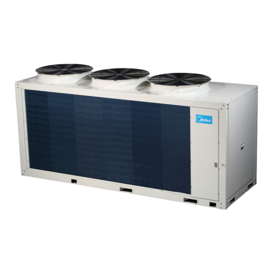
Midea Aqua Tempo Super II Series Engineering Data

Midea Aqua Tempo Super II Series Engineering Data

Commercial air conditioners
Hide thumbs Also See for Aqua Tempo Super II Series:

Advertisement

Advertisement

Table of Contents
loading
Need help?

Need help?

Do you have a question about the Aqua Tempo Super II Series and is the answer not in the manual?

Questions and answers

Summary of Contents for Midea Aqua Tempo Super II Series

  • Page 2: Table Of Contents

    Aqua Tempo Super II Part 1 General Information Aqua Tempo Super II System ..............4 Unit Capacities ..................5 Nomenclature ..................5 System and Design Unit Selection ............6 Typical Applications ................8 201902...
  • Page 3: Aqua Tempo Super Ii System

    Aqua Tempo Super II 1 Aqua Tempo Super II System 1.1 System Schematic Figure 1-1.1: System schematic Expansion tank Water replenishment valve Water discharge valve Master unit Y-type filter, unit requiring≥ 16 mesh Differential pressure by-pass valve unit Drain valve Slave unit Two-way valve Max 16 units...
  • Page 4: Unit Capacities

    L: Low ambient temp. cooling Refrigerant N1: R410A Power supply R: 380-415V/3phase/50Hz Hydraulic Module M: With hydraulic module Empty: Without hydraulic module Rated heating capacity (kW) Special function code U: DC inverter compressor Series code S: Super II Chiller Midea 201902...
  • Page 5: System And Design Unit Selection

    Aqua Tempo Super II 4 System and Design Unit Selection 4.1 Selection Procedure Step 1: Total heat load calculation Calculate conditioned surface area Select the heat emitters (type, quantity, water temperature and heat load) Step 2: System configuration Decide whether to enable or disable auxiliary electric heater Step 3: Selection of outdoor units Determine required total heat load on outdoor units Set capacity safety factor...
  • Page 6 Aqua Tempo Super II 4.2 Aqua Tempo Super II Leaving Water Temperature (LWT) Selection The recommended design LTW ranges for different types of heat emitter are:  For floor heating: 30 to 35⁰C  For fan coil units: 30 to 45⁰C ...
  • Page 7: Typical Applications

    Aqua Tempo Super II 5 Typical Applications 5.1 Space Heating Through Floor Heating Loops Floor heating Loops are used for spaces heating. Figure 1-5.1: Space heating through floor heating loops (standard unit without hydronic module) Expansion tank Water replenishment valve Water discharge valve Master unit Y-type filter,...
  • Page 8 Aqua Tempo Super II Figure 1-5.2: Space heating through floor heating loops (customized unit with built-in hydronic module) Expansion tank Water replenishment valve Water discharge valve Master unit Y-type filter, One-way requiring≥ 16 mesh unit valve Two-way Differential pressure valve by-pass valve One-way valve...
  • Page 9 Aqua Tempo Super II 5.2 Space Heating and Space Cooling Through Fan Coil Unit Fan coil units are used for space heating and cooling. Figure 1-5.3: Space heating and space cooling through fan coil unit (standard unit without hydronic module) Expansion tank Water replenishment valve Water discharge valve...
  • Page 10 Aqua Tempo Super II Figure 1-5.4: Space heating and space cooling through fan coil unit (customized unit with built-in hydronic module) Expansion tank Water replenishment valve Water discharge valve Master unit Y-type filter, One-way requiring≥ 16 mesh unit valve Two-way Differential pressure valve by-pass valve...
  • Page 11 Aqua Tempo Super II 5.3 Space Heating Through Floor Heating Loops And Space Cooling Through Fan Coil Unit Floor heating loops and fan coil units are used for space heating and fan coil units are used for space cooling. In space cooling mode, the 2-way valve is closed to prevent cold water entering the floor heating loops.
  • Page 12 Aqua Tempo Super II Figure 1-5.6: Space heating through floor heating loops and space cooling through fan coil unit (customized unit with built-in hydronic module) Expansion tank Water replenishment valve Water discharge valve Master unit Y-type filter, One-way requiring≥ 16 mesh unit valve Two-way...
  • Page 13 Aqua Tempo Super II 201902...
  • Page 14 Aqua Tempo Super II Part 2 Engineering Data Specifications ..................16 Dimensions and Center of Gravity ............19 Piping Diagrams ................... 22 Wiring Diagrams .................. 27 Capacity Tables ..................32 Operating Limits .................. 36 Hydronic Performance ................. 37 Sound Levels ..................40 Accessories ..................
  • Page 15 Aqua Tempo Super II 1 Specifications Table 2-1.1: Specifications MC-SU90-RN1L MC-SU30-RN1L MC-SU60-RN1L Model name 380-415/3/50 Power supply V/Ph/Hz 27.6 Capacity 36.8 10.95 21.83 Rated input Cooling 2.23 2.52 2.52 4.32 4.41 4.20 SEER 31.4 61.6 Capacity 32.8 10.64 20.07 Rated input Heating 2.74 2.95...
  • Page 16 Aqua Tempo Super II Table 2-1.2: Specifications MC-SU30M-RN1L MC-SU60M-RN1L Model name 380-415/3/50 Power supply V/Ph/Hz 28.2 Capacity 10.93 22.54 Rated input Cooling 2.58 2.44 3.72 3.73 SEER 30.8 Capacity 10.62 21.2 Rated input Heating 2.90 2.83 3.27 3.45 SCOP Seasonal space heating energy efficiency class 19.7 36.9 Max.
  • Page 17 Aqua Tempo Super II Table 2-1.3: Pump specifications Pump model name YKB-650-2-1 YKB-1500-2-1 Corresponding unit model name MC-SU30M-RN1L MC-SU60M-RN1L Power supply 380-415 V/3Ph/Hz 380-415 V/3Ph/Hz Rated power 0.65 KW 1.5 KW Rated current 1.6-1.8A 3.15A Rated water flow 4.7 m3/h 10m3/h Rated pump head 22.8 m...
  • Page 18: Dimensions And Center Of Gravity

    Aqua Tempo Super II 2 Dimensions and Center of Gravity MC-SU30(M)-RN1L Figure 2-2.1: MC-SU30(M)-RN1L dimensions and center of gravity (unit: mm) 1870 Top view Left view 1870 Hole for anchor bolt Φ15 Bottom view Front view 201902...
  • Page 19 Aqua Tempo Super II MC-SU60(M)-RN1L Figure 2-2.2: MC-SU60(M)-RN1L dimensions and center of gravity (unit: mm) Front view 2220 Top view Left view 2220 1105 Hole for anchor bolt Φ15 Bottom view Front view 201902...
  • Page 20 Aqua Tempo Super II MC-SU90-RN1L Figure 2-2.1: MC-SU90-RN1L dimensions and center of gravity (unit: mm) 201902...
  • Page 21: Piping Diagrams

    Aqua Tempo Super II 3 Piping Diagrams MC-SU30-RN1L Figure 2-3.1: MC-SU30-RN1L piping diagram EXVA Taf1 inlet Taf2 outlet Legend Compressor CCH (Crankcase heater ) Tp (DC inverter compressor discharge temperature sensor) Switch_Tp(Discharge temperature control switch ) PRO-H (High pressure switch) Oil separator 4-way valve Air side heat exchanger...
  • Page 22 Aqua Tempo Super II MC-SU30M-RN1L Figure 2-3.2: MC-SU30M-RN1L piping diagram EXVA Taf1 inlet Taf2 outlet Legend Compressor CCH (Crankcase heater ) Tp (DC inverter compressor discharge temperature sensor) Switch_Tp(Discharge temperature control switch ) PRO-H (High pressure switch) Oil separator 4-way valve Air side heat exchanger T4 (Outdoor ambient temperature) T3 (Air side heat exchanger temperature sensor)
  • Page 23 Aqua Tempo Super II MC-SU60-RN1L Figure 2-3.3: MC-SU60-RN1L piping diagram EXVA Taf1 inlet Taf2 outlet Heat3 Legend Compressor1 Compressor2 CCHA (Crankcase heater A) CCHB (Crankcase heater B) Switch_TpA (Discharge temperature control switch A) Switch_TpB ( Discharge temperature control switch B) Tp1 (DC inverter compressor 1 discharge temperature sensor) Tp2 (DC inverter compressor 2 discharge temperature sensor) PRO-H (High pressure switch)
  • Page 24 Aqua Tempo Super II MC-SU60M-RN1L Figure 2-3.4: MC-SU60M-RN1L piping diagram EXVA Taf1 inlet Taf2 outlet Heat3 Legend Compressor1 Compressor2 CCHA (Crankcase heater A) CCHB (Crankcase heater B) Switch_TpA (Discharge temperature control switch A) Switch_TpB ( Discharge temperature control switch B) Tp1 (DC inverter compressor 1 discharge temperature sensor) Tp2 (DC inverter compressor 2 discharge temperature sensor) PRO-H (High pressure switch)
  • Page 25 Aqua Tempo Super II MC-SU90-RN1L Figure 2-3.5: MC-SU90-RN1L piping diagram EXVA Taf1 inlet Taf2 outlet EXVC EXVB Legend Compressor1 Compressor2 CCHA (Crankcase heater A) CCHB (Crankcase heater B) Switch_TpA (Discharge temperature control switch A) Switch_TpB ( Discharge temperature control switch B) Tp1 (DC inverter compressor 1 discharge temperature) Tp2 (DC inverter compressor 2 discharge temperature) PRO-H (High pressure switch)
  • Page 26: Wiring Diagrams

    Aqua Tempo Super II 4 Wiring Diagrams MC-SU30(M)-RN1L Figure 2-4.1: MC-SU30(M)-RN1L wiring diagram 201902...
  • Page 27 Aqua Tempo Super II MC-SU60(M)-RN1L Figure 2-4.2: MC-SU60(M)-RN1L wiring diagram Brown DC fan drive board B Blue Brown DC fan drive board A Blue Black Black CN40 CN41 CN42 L1’ L3’ L2’ CN50 Black CN51 CN36 CN37 CN38 CN39 Blue White Black Black...
  • Page 28 Aqua Tempo Super II Legend H-PRO High pressure switch Eva-heat1 Plate heat exchanger heater 1 L-PRO Low pressure switch Eva-heat2 Plate heat exchanger heater 2 Water switch Water flow switch Inverter module temperature sensor 1 L-YL1 Pressure sensor Inverter module temperature sensor 2 Outdoor ambient temperature sensor Total water outlet temperature sensor Air side heat exchanger temperature sensor...
  • Page 29 Input and output of AC filter B Input and output of AC filter B Three phase bridge rectifier A&B Three phase bridge rectifier A&B Compressor drive board A&B Compressor drive board A&B...
  • Page 30 Power supply of compressor A&B Power supply of compressor A&B AC contactor input and output AC contactor input and output Pump input Pump input Please refer to the latest wiring diagram for more details.
  • Page 31 Aqua Tempo Super II MC-SU90-RN1L Figure 2-4.3: MC-SU90-RN1L wiring diagram 201902...
  • Page 32 Aqua Tempo Super II Legend FAN A/B/C DC fan Total water outlet temperature sensor Four-way valve Air suction temperature sensor Oil return solenoid valve Discharge temperature sensor 1 Multifunctional solenoid valve Discharge temperature sensor 2 Liquid side bypass solenoid valve Inverter module temperature sensor 1 SV8A injection solenoid value...
  • Page 33: Capacity Tables

    Aqua Tempo Super II 5 Capacity Tables 5.1 Heating Capacity Tables Table 2-5.1: MC-SU30(M)-RN1L heating capacity Chilled water outlet temperature (°C) 30.00 35.00 40.00 45.00 50.00 55.00 Ambient temp (°C) -15.00 17.38 8.03 16.06 8.22 16.80 8.60 15.35 9.65 -7.00 25.44 8.85 24.41...
  • Page 34 Aqua Tempo Super II Table 2-5.3: MC-SU90-RN1L heating capacity Chilled water outlet temperature (°C) Ambient 30.00 35.00 40.00 45.00 50.00 55.00 temp. (°C) -20.00 55.21 23.46 46.32 23.36 37.63 22.86 -15.00 62.23 23.93 51.23 23.29 42.32 24.89 35.87 25.17 -7.00 70.86 22.24 62.32...
  • Page 35 Aqua Tempo Super II 5.2 Heating Capacity Tables Table 2-5.4: MC-SU30(M)-RN1L cooling capacity Chilled water outlet temperature (℃) 5.00 7.00 10.00 13.00 15.00 20.00 Ambient Capacity Power Capacity Power Capacity Power Capacity Power Capacity Power Capacity Power temp. (°C) -10.00 22.69 6.13 25.88...
  • Page 36 Aqua Tempo Super II Table 2-5.6: MC-SU90-RN1L cooling capacity Chilled water outlet temperature (℃) 5.00 7.00 10.00 13.00 15.00 20.00 Ambient Capacity Power Capacity Power Capacity Power Capacity Power Capacity Power Capacity Power temp. (°C) -10.00 48.32 20.14 54.22 20.81 60.23 21.51 65.23...
  • Page 37: Operating Limits

    Aqua Tempo Super II 6 Operating Limits 6.1 Cooling operating range Figure 2-6.1: Cooling operating range Ambient temperature Outlet water temperature (Unit: ℃ ) Cooling operating range 6.2 Heating operating range Figure 2-6.2: Heating operating range MC-SU30(M)-RN1L/ MC-SU60(M)-RN1L Ambient temperature 25 30 40 45 50 52 55 Outlet water temperature...
  • Page 38: Hydronic Performance

    Aqua Tempo Super II 7 Hydronic Performance MC-SU30(M)-RN1L Figure 2-7.1: MC-SU30(M)-RN1L Hydronic performance 3.72 4.26 4.79 5.32 Water flow rate (m MC-SU60(M)-RN1L Figure 2-7.2: MC-SU60(M)-RN1L Hydronic performance 7.33 8.37 9.42 10.47 Water flow rate (m 201902...
  • Page 39 Aqua Tempo Super II MC-SU90-RN1L Figure 2-7.3: MC-SU90-RN1L Hydronic performance 6.45 10.83 12.51 14.77 15.67 Water flow rate (m 201902...
  • Page 40 Aqua Tempo Super II MC-SU30M-RN1L Figure 2-7.4: YKB-650-2-1 Hydronic performance Water flow rate (m MC-SU60M-RN1L Figure 2-7.5: YKB-1500-2-1 Hydronic performance Water flow rate (m 201902...
  • Page 41: Sound Levels

    Aqua Tempo Super II 8 Sound Levels 8.1 Overall Table 2-8.1: Sound pressure levels Model name dB(A) MC-SU30-RN1L 65.8 MC-SU30M-RN1L 68.0 MC-SU60-RN1L 72.1 MC-SU60M-RN1L 73.0 MC-SU90-RN1L 80.1 Notes: Sound pressure level is measured at a position 1m in front of the unit and (1+H)/2m (where H is the height of the unit) above the floor in a semi-anechoic chamber.
  • Page 42 Aqua Tempo Super II 8.2 Octave Band Levels Figure 2-8.2: MC-SU30(M)-RN1L octave band level (in cooling mode at rated compressor frequency) NR-90 NR-80 NR-70 NR-60 NR-50 NR-40 NR-30 NR-20 NR-10 NR-0 31.5 1000 2000 4000 8000 Octave band central frequency (Hz) Figure 2-8.3: MC-SU60(M)-RN1L octave band level (in cooling mode at rated compressor frequency) NR-90 NR-80...
  • Page 43 Aqua Tempo Super II Figure 2-8.4: MC-SU90-RN1L octave band level (in cooling mode at rated compressor frequency NR-90 NR-80 NR-70 NR-60 NR-50 NR-40 NR-30 NR-20 NR-10 NR-0 31.5 1000 2000 4000 8000 Octave band central frequency (Hz) Figure 2-8.5: MC-SU30(M)-RN1L octave band level (in heating mode at rated compressor frequency) NR-90 NR-80 NR-70...
  • Page 44 Aqua Tempo Super II Figure 2-8.6: MC-SU60(M)-RN1L octave band level (in heating mode at rated compressor frequency) NR-90 NR-80 NR-70 NR-60 NR-50 NR-40 NR-30 NR-20 NR-10 NR-0 31.5 1000 2000 4000 8000 Octave band central frequency (Hz) Figure 2-8.7: MC-SU90-RN1L octave band level (in heating mode at rated compressor frequency) NR-90 NR-80 NR-70...
  • Page 45: Accessories

    Aqua Tempo Super II 9 Accessories 9.1 Standard accessories Table 2-9.1: Standard accessories Quantity MC-SU30(M)-RN1L Name Shape MC-SU60(M)-RN1L MC-SU90-RN1L Installation & Operation Manual Temperature testing components for total water outlet Wired controller power adapter Wired controller installation manual 201902...
  • Page 46   A Aqua Tem mpo Supe er II     art  3    stal llat  an d    ld S Sett ting gs  1  Pref face to Pa rt 3 .................. 46  2  Unit t Placeme ent and In stallation   ............. 47 ...
  • Page 47 ua Temp po Super  II     Preface to  Part 3  Notes for I nstallers Bo oxes  The  information  contained  in n  this  Engine eering  Data  B Book  may  pr imarily  be  of f  use  during  the  system  design  stage   of  a  Mide ea  Aqua  Tem mpo ...
  • Page 48   A Aqua Tem mpo Supe er II     Unit Placem ment and  Installati on  Acceptance e and Unpa acking   otes for inst tallers    When  un its  are  delive ered  check  w whether  any  damage  occ curred  durin g  shipment.  If  there  is  d damage  to  th he ...
  • Page 49 ua Temp po Super  II     igure 3‐2.1: Ho isting the unit  the an ngle of inclin naton he angle of in nclinaton Lifted hook   Placement  Considerat tions  Plac ement of out tdoor units sh hould take ac ccount of the  following co onsiderations :   Outdoor uni its should no t be exposed  to direct rad diation from a a high‐tempe erature heat s source. ...
  • Page 50   A Aqua Tem mpo Supe er II     units.   Outdoor un its can be ins stalled on the e ground or o on a roof str ucture that i s strong eno ugh to bear  the unit’s we eight.  When instal lled in a posit tion that is no ot easily acce essible, a met thod of safe  access for ins stallation/ma aintenance sh hould  be provided .   Outdoor uni its should no t be installed d in locations  which have s stringent low ‐noise or low w‐vibration re equirements.
  • Page 51 ua Temp po Super  II     Drainage channel Ancho r bolt     MC‐SU90 ‐RN1L     Drainage    Drai nage ditch sh hould be pro ovided to allo ow drainage o of condensat te that may f form on the  air side heat t exchanger w when  the  unit  is  runni ng  in  heating g  mode.  The drainage  sh ould ...
  • Page 52   A Aqua Tem mpo Supe er II     Input of a airflow Main u unit Main un Main unit Main u unit Main un Main unit Main u unit Main un Main unit nput of airflow Multiple units s installation    Table e 3‐2.1: Recomm mend minimum m spacing ...
  • Page 53 ua Temp po Super  II       Figu ure 3‐2.5: Install l ation of the da amper  Anchor bolt M12 Ferrol Fixed meat Damping g device plate                                        ...
  • Page 54   A Aqua Tem mpo Supe er II     Water Syst tem Desig gn and Inst tallation Water Circu uit Checks  Aqua a Tempo Sup per II units are e equipped w with a water i inlet and out let for conne ction to a wa ater circuit. A Aqua Tempo S Super  II  un nits  should  o nly  be  conne ected  to  clos ed  water  circ cuits.  Connec ction ...
  • Page 55 ua Temp po Super  II     Table 3‐3.1: App plicable standar rd of water qua ality for the unit t  pH  Total  Conducti ivity  Sulfide e ions  Chlor ide  Ammon nia  Sulfate  Silicon ron    Sodi ium    Calciu um  alue  hardnes ss  ions s  ions ions ns  ions s  7‐  < 50ppm m ...
  • Page 56   A Aqua Tem mpo Supe er II     3.2.5 5 Fouling fact tor  Foul ing  refers  to   the  accumu ulation  of  unw wanted  mate erial  on  solid d  surfaces,  m most  often  in  an  aquatic  e environment .  The  fouli ing material c can consist o of either living g organisms ...
  • Page 57 ua Temp po Super  II     Installation n of Water S System Pipe eline  3.3.1 1 Installation n of single‐mo odule water  system pipel line    igure 3‐3.1: Ins stallation of sing gle‐module wat ter system pipe eline  ater inlet  Wate er outlet      Figur re 3‐3.2: connec ction method of f MC‐SU30(M)‐ ‐RN1L    Figur re 3‐3.3: connec ction method of f MC‐SU60(M)‐ ‐RN1L    56  01902 ...
  • Page 58   A Aqua Tem mpo Supe er II       Figur re 3‐3.4: connec ction method of f MC‐SU90‐RN1 1L      3.3.2 2 Installation n of multi‐mo odule water s system pipeli ine    igure 3‐3.5: Inst tallation of mul lti‐module wate er system pipeli ine  No.n m odule No.(n-1) mo odule No.1 module No.(n-1) a address No.(n-2) add dress No.0 address Drill dead...
  • Page 59 ua Temp po Super  II     Main water  outlet tempe erature sensin ng bulb and a auxiliary elect tric heater ar re under cont trol of the ma ain module. The unit can n be started u up through th he wired cont troller only af fter all addre sses are set a and the afore ementioned i items  are determi ned. The wire ed controller  is ≤500m aw way from the o outdoor unit .    3.3.4 4 Chiller wate er flow    Mini imum  chilled d ...
  • Page 60   A Aqua Tem mpo Supe er II       igure 3‐3.8: Des sign of the stor re tank rror Recomm mendation Error         Chill led water sys stem minimu um water volu ume  Chill ed water sys tem water vo olume can be e calculated a as:            Chilled wate er system wat ter volume    =    Water  pipework vo lume ...
  • Page 61 ua Temp po Super  II     • Where:  •   is s  the  unit’s  c cooling  capa city  (in  kW)  corrected  fo or  ambient  te emperature  (using  the  lo owest  expe ected cooling g mode ambie ent temperat ture) and leav ving water tem mperature  •   is the ratio o of unit outpu ut at its lowes st operating ...
  • Page 62   A Aqua Tem mpo Supe er II            = 25.7 x 86 60 x 0.12 = 26 652kcal  Qd‐  = 24.4 x x 860 x 0.12 = = 2518kcal  2⁰C 7⁰C    = 25.7 x 860 0 x (4/60) = 1 1473kcal     = 24.4 x 8 860 x (4/60) = = 1399kcal    2⁰ ‐7⁰C   ΔTt  = 3 30 ‐ 15 = 15⁰C C  ΔTt  = = 35 ‐ 20 = 15 5⁰C  2⁰C ‐7⁰C  ...
  • Page 63 ua Temp po Super  II     H3: W Water resista ance of the lo ongest water‐ ‐loop distanc ce, includes: p pipe resistanc ce, different v valve’s resista ance, flexible e pipe  resis stance, pipe e elbow and th ree‐way resis stance, two‐w way resistanc e or three‐wa ay resistance, , as well as fi lter resistanc e.  H4: t the longest te erminal resist tance.    Insta all the pump: :  The  pump  s should  be  in nstalled ...
  • Page 64   A Aqua Tem mpo Supe er II     lectrical W Wiring  General   otes for inst tallers  aution   All  install lation  and  w wiring  must  b e  carried  ou t  by  compet ent  and  suit ably  qualified d,  certified  a and  accredite ed  professio nals and in ac ccordance wi...
  • Page 65 ua Temp po Super  II     342V‐418V.       All electric w wires must co onform to lo ocal wiring co onnection no rm. The suita able cables s hould be con nnected to p ower  supply term inal through  wiring conne ection holes a at the bottom m of the elect ric cabinet. A According to C Chinese stand dard,  the user is re esponsible fo or providing v voltage and c current prote ction for the  input power  supply of the e unit.      ...
  • Page 66   A Aqua Tem mpo Supe er II       Wiring Step ps  Tabl le 3‐4.2: Wiring g steps  Step  Conten nt  Check th he unit and ens sure that it is co onnected with g grounding wire es correctly, to a avoid leakage, a and the ground ding devices  1  should b be mounted in  strict accordan nce with the req quirements of e electrical engin eering rules. Th he grounding w wires can preven nt  electric  shock.  2  The con ntrol box of the ...
  • Page 67 ua Temp po Super  II       Figur re 3‐4.3: wire co onnection of au uxiliary electric  heaters for MC C‐SU90‐RN1L  L1/L2/L3 Connetcor X XT1 in the electri ic box HEAT1 Control coil of 3 phaseAC c contactor Overcurrent re elay     Figur re 3‐4.4: wire co onnection of pu ump for MC‐SU3 30(M)‐RN1L an d MC‐SU60(M) )‐RN1L ...
  • Page 68   A A qua Tem m po Supe er II     4.5  Wiring Ove erview    Figur re 3‐4.6: diagra m combination n  system of MC‐ ‐ SU30(M)‐RN1L L     2019 902  67 ...
  • Page 69 ua Temp po Super  II     Figur re 3‐4.7: diagra m combination n system of MC‐ ‐ SU60(M)‐RN1L L     68  01902 ...
  • Page 70   A Aqua Tem mpo Supe e r II     Figur re 3‐4.8: diagram combination n  system of MC‐ ‐SU90‐RN1L    2019 902  69 ...
  • Page 71 ua Temp po Super  II     Table 3‐4.2: Wiri ing requiremen nts    Required nu umber of  Maximum run nning  tem  Descriptio on  Current Mini imum wiring si conduc ctors  current  1  1  User interface e wire AC  200mA  0.75‐1.25mm 2  xiliary heater co ontrol wire  AC  200mA  0.75mm   3  Pump contro ol wire  AC  200mA ...
  • Page 72   A Aqua Tem mpo Supe er II     Modbus Ga ateway (cus stomization n option)  dbus Gateway y functionalit ty can be add ded by adding g X, Y, E ports s to the wired d controller. U Up to 16 wire ed controllers s   can  be connecte ed together, w with each con ntroller contr rolling up to 1 16 units.      igure 3‐4.9: Mo odbus Gateway y wiring connect tion               ...
  • Page 73 ua Temp po Super  II     ield Settin ngs  Table 3‐5.1 :Mai in PCB switch se ettings for MC‐S SU30(M)‐RN1L and MC‐SU60( (M)‐RN1L    Default factor ry  Switc ch  Description n  ON  OFF  setting  S5‐1  ter outlet temp perature   srved    Normal    OFF  S5‐2  ON/OFF funct tion  ivated  Deactivated  OFF    One large  One sm mall pump ...
  • Page 74   A A qua Tem mpo Supe er II     Outdoor unit t address    0: maste r unit  C4  ‐ ‐  0  1,2,3…F: sla ave units    Notes s:  Normal water o utlet temperatur re range: 5⁰C to 2 20⁰C.                               ...
  • Page 75 ua Temp po Super  II     Commissio oning and  Maintena ance  Commissio oning  6.1.1 1 Preparation n     After  the  w water  system   pipeline  is  flushed  seve eral  times,  p please  make  sure  that  th he  purity  of  water  meets s ...
  • Page 76   A Aqua Tem mpo Supe er II     6.2.2 2 Removing s scale    Afte r  long‐time  o operation,  ca alcium  oxide  or  other  min nerals  will  be e  settled  in  t he  heat  tran nsfer  surface  of  the  water r‐side  heat t ...
  • Page 77 ua Temp po Super  II     parameters. . Refrigerant  must be inje cted from the e low pressur re side of sys tem.     The  injectio on  amount  of f  refrigerant  will  be  affec cted  by  the  a ambient  tem perature.  If  the  required d  amount  has s  not  been reache ed but no mo ore injection ...
  • Page 78   A Aqua Tem mpo Supe er II     User Interf face Field  Settings f for KJRM‐ 120H/BM MWKO‐E  Introductio on    Duri ng  installatio on,  the  unit’ ’s  settings  a nd  paramete ers  should  b be  configured d  by  the  ins staller  to  sui it  the  install ation ...
  • Page 79 ua Temp po Super  II     General Op peration  7.2.1 1 Unlocking/ /Locking oper ration  en the wired  controller is  locked, press s and hold the e "UNLOCK"  button for 2s s to unlock it; ; when "    " i is not display yed in  the  locked  statu s,  press  and  hold  the  "U NLOCK"  butt ton  for  2s  to o  lock  it.  Whe en ...
  • Page 80   A Aqua Tem mpo Supe er II     As sh hown below:  three modes s available.    igure 3‐7.1: Diff fferent mode in terfaces ooling mode  Heating mod de  Water pump  mode        en the curren nt mode butto on is selected d (blinking), p press "      " an nd "      " to s et a mode or r temperature e, and then p press  "▼" " and "▲" to ...
  • Page 81 ua Temp po Super  II     PROJECT M Menu    7.3.1 1 PROJECT m menu structur re    or PROJECT M Menu  1.STATE QUE ERY    . STATE QUE ERY  COMPRESSO OR STATE    . PARAMETE ERS QUERY  FAN STATE   . MANUAL D DEFROST  4‐WAY VALVE E STATE    . SILENT SET TTING  PUMP STATE E ...
  • Page 82   A Aqua Tem mpo Supe er II     7.3.2 2 Enter the P PROJECT  JECT allows i nstallers to in nput the syste em configura ation and set  the system p parameters. T To enter PROJ JECT, go to M ENU >  JECT.  Figure 3‐7.2 2: PROJRCT pass sword screen   ► to navigat Ente er the passwo ord, using ◄  te between d digits and usi ng ▼ ▲ to a adjust the num merical value es, and then  press  OK. T The password d is 6666. The en it will disp play the below w interface:...
  • Page 83 ua Temp po Super  II     b. Paramet ters query: EX XV opening d degree, comp pressor curren nt, high press sure, low pres ssure, anti‐fr eeze tempera ature,  condens ser pipe temp perature, disc charge tempe erature    gure 3‐7.5: Stat te query interfa       c. Manual   defrost    Figure 3‐7.6 6: Manual defro ost interface d. Silent se etting: standa ard mode, sile ent mode, nig ght silent mo ode (factory d default setting g), super silen...
  • Page 84   A Aqua Tem m po Supe e r II     Clearing g history erro o r    Fi i gure 3‐7.9: Clearing history er rror interface                                         2019 9 02  83 ...
  • Page 85 ua Temp po Super  II     7.3.4 4 Parameters s setting    Table 3‐7. 2: Parameters s setting  parameters  Sett ting range  Default value e  Adjustm ment range  frosting cycle  20 min n to 120 min 35 min  min  Defrost e enter temperat ture  ‐5⁰ ⁰C to 5⁰C  0⁰C  1⁰C  Defrost t exit temperatu ure  ‐10⁰C C to +10⁰C  0⁰C  1⁰C  Manu ual defrost ente r ...
  • Page 86   A Aqua Tem mpo Supe er II     User Interf face Field  Settings f for KJRM‐ 120H/BM MWKO3‐E Introductio on  Duri ng  installatio on,  the  unit’ ’s  settings  a nd  paramete ers  should  b be  configured d  by  the  ins staller  to  sui it  the  install ation ...
  • Page 87 ua Temp po Super  II     Menu oper ration  8.2.1 1 Unlocking/ /Locking oper ration    en the wired  controller is  locked, press s and hold the e "UNLOCK"  button for 3s s to unlock it; ; when "    " i is not display yed in  the  locked  statu s,  press  and  hold  the  "U NLOCK"  butt ton  for  3s  to o ...
  • Page 88   A Aqua Tem mpo Supe er II       8.2.5 5 Auto‐restar rt function  The  power  supp ly  to  the  syst tem  fails  une expectedly  d uring  operat ion.  When  th he system  is  powered  on n  again,  the  w wired  cont troller contin ues to opera ate according g to the statu...
  • Page 89 ua Temp po Super  II     en set addres ss “01‐15” an d press “OK” button, the w wired contro oller will ente r the interfac ce as follows.     gure 3‐8.6: Mai in page for slav ve wired contro ller 10:35 A 20/11/2017 ONLIN E CO O OL Tws 55 C UNITE S 55 C ERRO R 55 C PRESS S MENU TO QUERY S STATUS  ...
  • Page 90   A Aqua Tem mpo Supe er II     Setting PRO OJECT MEN NU  8.3.1 1 PROJECT m menu structur re    or PROJECT M Menu  1.STATE SET  UNIT    . SET UNIT  AIR‐CONDIT TIONING    AIR‐COND DITIONING  Tw_cool_Dif ff    . SET PARAL LLEL  Tw_heat_Dif ff    . SET UNIT P PROTECTION  dT5_ON ...
  • Page 91 ua Temp po Super  II     8.3.2 2 Entering th he password  Sele ct  "PROJECT  T  MENU",  an d  press  the  "OK"  button n  to  enter  th he  menu.  Th he  screen  pr rompts  the  u user  to  ente r  the  pass sword is show wn as below. ...
  • Page 92   A Aqua Tem mpo Supe er II     Set unit air‐c conditioning  Sele ct "SET UNIT  AIR‐CONDIT IONING", and d press the "O OK" button to o enter the in nterface. The  interface dis splay is as foll lows.    igure 3‐8.10: Se et unit air‐cond ditioning interfa   PROJEC T MENU SELECT THE Q QUERING ADDRES S Tw_heat Tw_cool _Di f f _Di f f  ...
  • Page 93 ua Temp po Super  II       Pres ss the “▲”   and “▼”   b buttons to se t the values a and press “O K” button to  save the sett ting and retu rn to the prev vious  inter rface, or pres ss the "BACK " button to c ancel the set tting and retu urn to the pr evious interfa ace. If there  is no operati on in  60 se econds, the w wired control ller will retur n to the hom me page.    Set defrostin ng  “OK” button Sele ct “SET DEFR...
  • Page 94   A Aqua Tem mpo Supe er II       Note es:    The value of  “Tw_Heat1_ _OFF” is bigge er than “Tw_H Heat1_ON”. HEAT2 functi ion is disable d, so user ca nnot enter th he HEAT2 inte erface.    Check parts  Sele ct "CHECK PA ARTS", and pr ress the "OK" " button to en nter the inter rface. The int erface displa ay is as follow ws.    Figure 3‐8 8.16: Check part ts interface   back  ...
  • Page 95 ua Temp po Super  II     Appendix    Error Code  Table of M MC‐SU30(M) )‐RN1L and  MC‐SU60(M M)‐RN1L    able 3‐9.1: Error r code table of  MC‐SU30(M)‐R RN1L and MC‐SU U60(M)‐RN1L Error code  Content  1E0  Main PCB EEPRO OM mismatch 2E0  nverter module e A EEPROM mi smatch  3E0  nverter module e B EEPROM mi smatch  E1  Power phase se quence error E2  Communication  error between n main PCB and  wired controlle er ...
  • Page 96   A Aqua Tem mpo Supe e r II     Fb  Pressure sensor  error  Fd  Air suction temp perature(Th) pr rotection error 1FF  DC fan 1 error  2FF  DC fan 2 error  FP  DIP inconsistenc cy of multiple w water pumps (m manual recovery y)  L0  nverter module e protection  L1  DC bus low volta age protection L2  DC bus high volt tage protection n  L4  MCE error  L5  Zero speed prot tection  L7 ...
  • Page 97 ua Temp p o Super  II     P6  nverter module e protection  P7  Air‐side heat exc changer tempe erature and tota al cooling outlet t high temperat ture protection n  P9  Water‐side heat t exchanger inle et/outlet tempe erature differen nce protection  Pb  System anti‐free ezing protection n  PC  Evaporator pres sure low in coo oling mode  PE  Low‐temperatur re protection of f evaporator (m manual recovery y)  PH  Ambient tempe rature(T4)high  temperature p protection in he ating mode ...
  • Page 98   A Aqua Tem mpo Supe er II       System Che eck Table  Pres ss buttons SW W3 and SW4 s simultaneous ly to activate e the system c check functio on. The param meters listed  in Table 3‐9.3 3 and  Table e 3‐9.4 will b e displayed in n sequence.      Table e 3‐9.3: System  check table of M MC‐SU30(M)‐R RN1L and MC‐SU U60(M)‐RN1L No.  Para ameters displa ayed on DSP2 Standby y: ODU address s (DSP1 display)  + number of o on‐line units (DS SP1 display) ...
  • Page 99 ua Temp po Super  II     26  EXV 1 p osition(step=va alue displayed * 27  EXV 2 p osition(step=va alue displayed * 28  Compre essor discharge  pressure  29  Compre essor suction pr ressure  30  Air suct ion superheat d degree  31  Air suct ion temperatur re(Th) 32  Silent se election  33  Static p ressure selectio on  34  DC bus  low voltage 1 ( reserved)  35 ...
  • Page 100   A Aqua Tem mpo Supe er II     5  Outlet w water temperat ture(Two)  6  Total co ooling outlet tem mperature(Tz)  7  Heat rec covery sensor t temperature (T HeatR) (‐‐displa ayed)  8  Compre essor discharge  temperature 1 1 (sensor Tp1) 9  Compre essor discharge  temperature 2 2 (sensor Tp2) 0  Compre essor module te emperature(Tf1 1)  1  Compre essor module te emperature(Tf2 2) ...

This manual is also suitable for:

Mc-su30-rn1lMc-su60-rn1lMc-su90-rn1l

Table of Contents