Table of Contents
Advertisement
Quick Links
F e d e r a l C o m m u n i c a t i o n s C o m m i s s i o n S t a t e m e n t ( C l a s s A)
NOTE- This equipment has been tested and found to comply with the limits for a
Class A digital device, pursuant to Part 15 of the FCC Rules. These limits are
designed to provide reasonable protection against harmful interference in a
residential installation. This equipment generates uses and can radiate radio
frequency energy and, if not installed and used in accordance with the instructions, may cause
harmful interference to radio communications. However, there is no guarantee that interference
will not occur in a particular installation. If this equipment does cause harmful interference to
radio or television reception, which can be determined by tuning the equipment off and on, the
user is encouraged to try to correct the interference by one or more
Reorient or relocate the receiving antenna.
Increase the separation between the equipment and receiver.
Connect the equipment into an outlet on a circuit different from that to which the receiver is
connected.
Consult the dealer or an experienced radio/television technician for help.
C l a s s A I T E :
Class A ITE is a category of all other ITE which satisfies the class A ITE limits but not the class
B ITE limits. Such equipment should not be restricted in its sale but the following warning shall
be included in the instructions for use:
Warning - This is a class A product. In a domestic environment this product may cause radio
interference in which case the user may be required to take adequate measures.
C O P Y R I G H T
© 2012 AVer Information Inc. All rights reserved.
All rights of this object belong to AVer Information Inc. Reproduced or transmitted in any form,
or by any means without the prior written permission of AVer Information Inc. is prohibited. AVer
Information Inc. reserves the rights to modify its products, including their specifications and any
other information stated herein without notice. The official printout of any information shall
prevail should there be any discrepancy between the information contained herein and the
information contained in that printout. "AVer" is a trademark owned by AVer Information Inc.
Other trademarks used herein for description purpose only belong to each of their companies.
N O T I C E
SPECIFICATIONS
ARE
INFORMATION CONTAINED HEREIN IS TO BE CONSIDERED FOR REFERENCE ONLY.
W AR N I N G
TO REDUCE RISK OF FIRE OR ELECTRIC SHOCK, DO NOT EXPOSE THIS APPLIANCE TO
RAIN
OR
MOISTURE.
MODIFICATION.
THE MARK OF CROSSED-OUT WHEELED BIN INDICATES THAT THIS
PRODUCT MUST NOT BE DISPOSED OF WITH YOUR OTHER
HOUSEHOLD WASTE. INSTEAD, YOU NEED TO DISPOSE OF THE
WASTE EQUIPMENT BY HANDING IT OVER TO A DESIGNATED
COLLECTION POINT FOR THE RECYCLING OF WASTE ELECTRICAL
AND ELECTRONIC EQUIPMENT. FOR MORE INFORMATION ABOUT
WHERE TO DROP OFF YOUR WASTE EQUIPMENT FOR RECYCLING,
PLEASE CONTACT YOUR HOUSEHOLD WASTE DISPOSAL SERVICE
OR THE SHOP WHERE YOU PURCHASED THE PRODUCT.
SUBJECT
TO
CHANGE
WARRANTY
VOID
of the following measures:
WITHOUT
PRIOR
FOR
ANY
UNAUTHORIZED
ENGLISH
NOTICE.
THE
PRODUCT
Advertisement
Table of Contents

Related Manuals for AVer AverVision M70


Summary of Contents for AVer AverVision M70
- Page 1 © 2012 AVer Information Inc. All rights reserved. All rights of this object belong to AVer Information Inc. Reproduced or transmitted in any form, or by any means without the prior written permission of AVer Information Inc. is prohibited. AVer Information Inc.
- Page 2 ENGLISH Remote Control B a t t e r y S a f e t y I n f o r m a t i o n Store batteries in any cool & dry place. Do not dispose used batteries in domestic waste. Dispose batteries at special collection points or return to stores if applies.
-
Page 3: Table Of Contents
ENGLISH Package Contents ................1 Optional Accessories ..............1 Get Familiar with the AVerVision M70 ........... 2 Right Panel ..................... 2 Rear Panel ..................... 3 Left Panel ....................3 Control Panel ..................4 ... - Page 4 ENGLISH Spotlight ..................21 Visor....................21 PIP ....................22 Split Screen ..................22 Timer ....................23 Setting ....................23 Capture ................... 23 Resolution ..................23 Quality .................... 23 Type ....................24 Interval ....................
- Page 5 ENGLISH RS-232 Send Command Table ............. 32 RS-232 Get Command Table ............... 37 Troubleshooting ................38 Limited Warranty ................39 ...
-
Page 6: Package Contents
ENGLISH Make sure the following items are included in the package. RS-232/CVBS Cable Anti-glare Sheet USB Cable RGB Cable AVerVision M70 Remote Control (batteries included) Power Adapter (12V, 2A) * The power adapter will vary Software & Manual CD depending on the standard power outlet of the country where it is sold. -
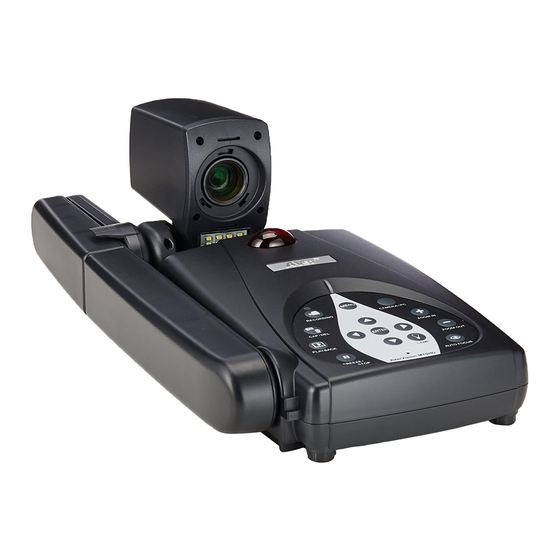
Page 7: Get Familiar With The Avervision M70
ENGLISH (fig. 1.1) Name Function Camera head Contain the camera sensor. Camera lens Focus the image in the camera. Control panel Easy access to various functions. Built-in MIC Record audio when recording video clip. The recorded sound will be in monophonic. Extendable for viewing coverage. -
Page 8: Rear Panel
Input the signal from a computer or other sources and pass it through to the RGB OUT port only. Connect this port to the RGB/VGA output port of a computer. RGB OUTPUT port Connect the AVerVision M70 to any display device with RGB cable L eft P ane l (fig. 1.4) -
Page 9: Control Panel
ENGLISH Cont rol Panel (10 ) (11) (12 ) (13 ) (fig. 1.5) Name Function MENU Open and exit the OSD menu. RECORDING Start/Stop audio & video recording. Audio and video recording can be saved on a SD card or an USB Flash drive only. See External Memory Storage. -
Page 10: Remote Control
ENGLISH Remote Cont rol The remote control requires two (2) “AAA” size batteries (supplied), make sure batteries are installed properly before use. You can access all the features of AVerVision M70 with the remote. Name Function POWER Turn the unit on/standby. - Page 11 ENGLISH Name Function ISOR Call the Visor submenu. Visor covers part of the presentation screen and allo presenter to reveal the material as (26 ) desire. (25 ) In the Vi sor submenu, the following (24 ) options are available. (23 ) (10) (22 )
- Page 12 ENGLISH Name Function (10) CAPTURE Capture still image in Camera mode. In continuous capture mode, press this button again to stop. (26 ) (11) RECORDING Start/Stop audio & video recording. (25 ) Video recording can only be saved (24 ) either in a SD memory card or a USB flash drive.
-
Page 13: Making The Connections
Before making the connection, make sure the power of all devices are turned off. If you are not sure on where to connect, simply follow the illustrated connections below and also refer to the user manual of the device you are connecting the AVerVision M70 with. The TV-RGB switch etermines the display output selection. -
Page 14: Connect To A Monitor Or Lcd/Dlp Projector
Locate the RGB (VGA) input port of the gr aphics display devic e and co nnect it to RGB OUTPUT port of AVerVision M70. Make sure the TV/RGB switch is set to RGB. RGB cable LCD/DLP projector CRT monitor LCD monitor Locate the HDMI input port of the display device and connect it to HDMI OUTPUT port of AVerVision M70. -
Page 15: Connect To A Tv
ENGLISH Locate the VIDEO or SCART RGB (if applicable) input port of the TV or Video equipment (i.e., VCR) to record your presentation and connect it to RCA jack of RS-232/CVBS cab RS-232/CVBS cable I N P U T P r o j e c t o r RCA cable VIDEO RCA to SCART cable... -
Page 16: Connect To A Computer
ENGLISH Locate the RGB (VGA) output port of the computer or laptop and connect it to RGB INPUT port of AVerVision M70. The video signal from the RGB INPUT port is streamed to RGB OUTPUT port. - To display computer image, press Camera/PC button on the control panel or remote control to switch AVerVision M70 to computer mode. -
Page 17: Connect An External Microphone
Take caution when using earphones. Adjust the volume down on the remote to prevent hearing damage due to loudness. Amplified Speaker Connect the AVerVision M70 to a microscope enables you to examine microscopic objects on a big screen. Change the image display mode to Microscope. - Page 18 ENGLISH Aim the camera head at the farthest point and press AUTO FOCUS. Adjust the focus of the microscope. Select the appropriate rubber coupler size for the microscope eyepiece and insert it in the microscope adapter. Remove the microscope eyepiece from t he microscope and connect it to icroscope adapter with the...
-
Page 19: Setting Up Avervision M70
Setting Up AVerV ision Setting Up AVerV ision This section provides useful tips on how to adjust the AVerVision M70 to meet your needs. The camera head can turn freely at 90° to t he left and right and up and down. -
Page 20: Infrared Sensor
ENGLISH Aim the remote control at the infrared sensor to operate the unit. Aim the remote control at the infrared sensor to operate the unit. Measure and mark the horizontal of 75 mm and vertical of 70 mm center line distance between the holes on the flat surface as describe in the illustration below. -
Page 21: External Memory Storage
(FAT SD Card Make sure to set the USB Flash Drive switch (see fig. 1.2 #1) to the right before inserting a USB flash drive. AVerVision M70 can support USB flash drive from 2GB to 32GB (FAT). USB Flash Drive... -
Page 22: Osd Menu
ENGLISH There are 4 tabs on the OSD menu: IMAGE, PRESENTATION, SETTING and SYSTE In Playback mode, you can access PLAYBACK OSD menu to enable the Slide Show feature and modify Slide Show interval and transition setting if desire. For TV output, the RESOLUTION will be disabled in SETTING menu list. PRESENTATION IMAGE SYSTEM... -
Page 23: Navigate The Menu And Submenu
ENGLISH 1. Press MENU button on the remote or control panel. 2. Press ► and ◄ to toggle between tabs 3. Press ▼ and ▲ to choose a selection in th menu list. 4. Press to make a selection. 5. Use ► and ◄ to adjust the setting or make a selection. -
Page 24: Mode
ENGLISH Menu Screen Function Mode Select from the various image display settings. Sharp - adjust the contrast along the edges making text appear more visible. Graphics - adjust the gradient of image. Motion - increase frame rate. Sufficient lighting is required when using this mode. -
Page 25: Auto Image
ENGLISH Menu Screen Function Auto Image Select ON or OFF to automatically adjust the wh balance and exposure setting, and correct the color and exposure compensation. Exposure ect the exposure setting. AUTO - automatically adjust the camera exposure and the amount of light required. MANUAL - manually adjust the exposure level. -
Page 26: Presentation
ENGLISH Menu Screen Function Spotlight Spotlight overlays a fram e on the presentation screen. You can move the Spotlight around the presentation screen using the ▲, ▼, ◄, & ► buttons. Select Execut e to call the Spotlight submenu. In the Spotlight submenu, th following options are available. -
Page 27: Pip
ENGLISH Menu Screen Function In the Visor submen u, the following opti ons are available. ON/OFF – select to run/canc el the Visor. Press move to the next selection. Shade – set the opa city level of the covered area. The shaded ar ea will com pletely turns black when it is set to... -
Page 28: Timer
ENGLISH Menu Screen Function Timer Start/Pause/Stop the timer and set the timer duration. The timer automatically counts up after the count down reaches zero to show the elapsed time. Even when you switch between Playback, PC or Camera modes, the timer will continue. -
Page 29: Type
ENGLISH Menu Screen Function Type Select the capture type. Single - capture one picture only. Continuous - capture successive pictures. Interval Set the time interval for continuous capture. The length can be set up to 600 sec (10 min). Recording Select the video recording compression setting. -
Page 30: Usb To Pc
ENGLISH Menu Screen Function USB to PC Select the status of the AV erVi sion M 70 when it is connected to the computer via USB . Make sure the USB switch on the left panel is set to Camera - can be used as a computer webcam or with our bundled software to record video and capture still image. -
Page 31: Backup
ENGLISH Menu Screen Function Backup Copy the image from the built-in memory to SD car d or USB flash drive. Save Setting Save cur rent setting in the selected profile number. Only effect, mode, brightness and contrast settings can be saved. -
Page 32: Playback
ENGLISH Menu Screen Function Slide Show Display all captured still pictures in an automated slide show. The video file will be skipped. Interval Set the interval before displaying the next picture. The length can be set up to 100 sec. Slide Show Effect Select the slide show transition effect. -
Page 33: Annotation
- 1280 x 720 1280 x 1024 Connecting a USB mouse or AP20T 1. Set the USB switch on the left panel to . AVerVision M70 will then detect the USB mouse and the LED on t control panel will light up. -
Page 34: Using The Annotation Control Panel
ENGLISH Using the Annot ation Control Panel The annotation control panel appears on the upper left corner of the screen. A cursor will appear on the screen. Move the cursor on the Annotation control panel selections and left- click to select the features you want to use. Name Function Select the line color. -
Page 35: Transfer Captured Images/Videos To A Computer
USB cable. 1. Make sure to set the USB switch to for the computer to detect AVerVision M70. 2. MUST set the USB to PC as STORAGE before connecting the USB cable. 3. When “Mass Storage Start…” appears at the lower... -
Page 36: Lighting
ENGLISH Lighting Lamp Type LED light Input/Output RGB Input 15-Pins D-sub (VGA) RGB Output 15-Pins D-sub (VGA) DMI Output HDMI CVBS/RS-232 Mini-DIN Jack (use CVBS/RS-232 Adapter cable) Composite Video RCA Jack USB2.0 DC 12V Input Power Jack Phone Jack Speaker Phone Jack Dimension Operating... -
Page 37: Rs-232 Cable Specifications
ENGLISH ake sure the RS -232 cable matches the cable specification design. PC COM Port AVerVision RS-232 Port DSUB-9P (Female DSUB-9P (Female) (CI) :1 bit Start bit :8 bit Data bit :1 bit Stop bit Parity b :None X param eter :None Baud rate (Com... - Page 38 ENGLISH Function Data[0] Data[1] Data[2] CheckSum POWER OFF 0x01 0x00 0x00 0x5a POWER ON 0x01 0x01 0x00 0x5b CAMERA MODE 0x02 0x00 0x00 0x59 PLAYBACK MODE 0x03 0x00 0x00 0x58 PC-1 PASS THROUGH 0x04 0x00 0x00 0x5f IMAGE CAPTURE TYPE: SINGLE 0x05 0x00 0x00...
- Page 39 ENGLISH Function Data[0] Data[1] Data[2] CheckSum EFFECT: COLOR 0x10 0x00 0x00 0x4b EFFECT: B/W 0x10 0x01 0x00 0x4a EFFECT: NEGATIVE 0x10 0x02 0x00 0x49 CONTRAST INCREASE 0x11 0x00 0x00 0x4a CONTRAST DECREASE 0x11 0x01 0x00 0x4b Value CONTRAST VALUE 0x11 0x02 [ ? ~ ? ] BRIGHTNESS INCREASE...
- Page 40 ENGLISH Function Data[0] Data[1] Data[2] CheckSum SPOTLIGHT RESIZE 0x1C 0x00 0x00 0x47 VISOR: OFF 0x1D 0x00 0x00 0x46 VISOR: ON 0x1D 0x01 0x00 0x47 VISOR SHADE: 50% dark 0x1E 0x00 0x00 0x45 VISOR SHADE: 100% dark 0x1E 0x01 0x00 0x44 PIP: OFF 0x1F 0x00...
- Page 41 ENGLISH Function Data[0] Data[1] Data[2] CheckSum FORMAT: THUMB DRIVE 0x29 0x02 0x00 0x70 OUTPUT RES OLUTION: 0x2F 0x01 0x00 0x75 1024x768 OUTPUT RESOLUTION: 0x2F 0x02 0x00 0x76 1280x720 OUTPUT RESOLUTION: 0x2F 0x03 0x00 0x77 1920x1080 OUTPUT RESOLUTION: 0x2F 0x04 0x00 0x70 1280 x 1024 OUTPUT RES...
-
Page 42: Rs-232 Get Command Table
ENGLISH Function Data[0] Data[1] Data[2] CheckSum AUTO FOCUS 0x40 0x00 0x00 0x1b MENU 0x41 0x00 0x00 0x1a ARROW - DOWN 0x42 0x00 0x00 0x19 ARROW - UP 0x42 0x01 0x00 0x18 ARROW - LEFT 0x42 0x02 0x00 0x1b ARROW - RIGHT 0x42 0x03 0x00... -
Page 43: Troubleshooting
M70 t sync up . Wait for around 4 to 7 seconds until you see the camera im age on the scree have set up th e AVerVision M70 and checked all th e conne ction s as spe cified... -
Page 44: Limited Warranty
You as the origin al purchaser. Except for the foregoing, the Product is provided “AS IS.” In no event does AVer warrant that You will be able to operate the Product without problems or inter ruptions, or that the Product is suitable for your purposes. Your exclusive remedy and the entire liability of AVer under this paragraph shall be, at AVer’s option, the repair or... - Page 45 RODUCT, WHETHER BASED ON CONTRAC T OR TORT, INCLUDING NEGLIGENCE, OR ANY THER LEGAL THEORY, EVEN IF AVER HAS ADVISED OF THE POSSIBILITY OF SUCH DAMAGES. AVER’S TOTAL, AGGREGATE LIABILITY FOR DAMAGES OF ANY NATURE, REGARDLESS OF FORM OF ACTION, SHALL IN NO EVENT EXCEED THE AMOUNT PAID BY YOU TO AVER FOR THE SPECI FIC PRODUCT UPON WHICH LIABILITY IS BASED.
Need help?
Do you have a question about the AverVision M70 and is the answer not in the manual?
Questions and answers