Table of Contents
Advertisement
Quick Links
I. DESCRIPTION AND SCOPE
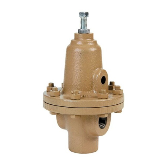
The Model BQ is a back pressure relief regulator used to control upstream (inlet or P
connections are 1/4", 3/8", and 1/2" NPT (DN8, DN10, DN15); outlet (bottom discharge) connection is always 1/2" NPT (DN15).
With proper trim utilization, the unit is suitable for liquid, gaseous, or steam service. Refer to Technical Bulletin BQ-TB for design
conditions and selection rec om men da tions.
This is not a safety device and must not be substituted for a code approved pressure safety relief valve or a rupture disc.
II. INSTALLATION
CAUTION
For welded installations, all internal trim parts, seals and
diaphragm(s) must be removed from reg u la tor body prior to
welding into pipeline. The heat of fusion welding will dam-
age non-metallic parts if not re moved. NOTE: This does
not apply to units equipped with extended pipe nip ples.
1.
An inlet block valve should always be installed.
2.
If service application is continuous such that shutdown
is not readily accomplished, it is recommended that
an inlet block valve, outlet block valve, and a manual
bypass valve be installed.
3.
Pipe unions should be installed to allow removal from
piping.
4.
An inlet pressure gauge should be located ap prox i mate ly
ten pipe diameters upstream and within sight. An outlet
pressure gauge is optional.
5.
All installations should include an upstream relief de vice
if the inlet pressure could exceed the pressure rating of
any equipment or the maximum inlet pres sure rating of
the unit.
WARNING
The maximum inlet pressure is equal to 1.5 times the larger
number of the stated range spring on the name plate, and is
the recommended "upper operative limit" for the sens ing
di a phragm. Higher pressures could damage the di a phragm.
(Field hy dro stat ic tests fre quent ly destroy di a phragms.
DO NOT HY DRO STAT IC TEST THRU AN IN STALLED UNIT;
ISOLATE FROM TEST.)
INSTALLATION, OPERATION & MAINTENANCE MANUAL (IOM)
MODEL BQ
BACK PRESSURE / RELIEF REG U LA TOR
SECTION I
SECTION II
CAUTION
Installation of adequate overpressure pro tec tion is recom-
mended to pro tect the reg u la tor from overpressure and
all down stream equip ment from damage in the event of
regulator failure.
Supply
@ P1
PI
SRV
Discharge
Recommended Piping Schematic
for Back Pressure/Relief Station
6.
Clean the piping of all foreign material including chips,
welding scale, oil, grease and dirt before installing the
regulator. Strainers are recommended.
7.
In placing thread sealant on pipe ends prior to en-
gage ment, ensure that excess material is removed
and not allowed to enter the regulator upon startup.
8.
Flow Direction: Install so the fl ow direction matches
the arrow cast on the body. Connect the inlet pressure
to the body side connection(s). Fluid will relieve out of
the bottom connection. The double inlet connections
are for in-line installation (plug one side connection if
in-line installation is not required).
9.
Regulator may be installed in a vertical or horizontal
pipe. If it is a steam system, ensure the piping is properly
trapped and vented.
IOM-BQ
) pressure. Side inlet and fl ow-thru
1
CAUTION
System
Demand
Model BQ
Bypass
BP/Relief
Regulator
P2
05-04
Advertisement
Table of Contents

Subscribe to Our Youtube Channel
Related Manuals for cashco BQ


Summary of Contents for cashco BQ
- Page 1 1/4", 3/8", and 1/2" NPT (DN8, DN10, DN15); outlet (bottom discharge) connection is always 1/2" NPT (DN15). With proper trim utilization, the unit is suitable for liquid, gaseous, or steam service. Refer to Technical Bulletin BQ-TB for design conditions and selection rec om men da tions.
-
Page 2: Principle Of Operation
14. Increase fl ow to maximum level if possible. Inlet (up- a cold system; i.e. do everything slowly. stream or P ) pressure should rise. Readjust setpoint as necessary at the normal fl ow rate. Crack open the inlet (upstream) block valve. IOM-BQ... -
Page 3: Maintenance
Relax range spring (11) by turning adjusting screw (13) CCW until removed from spring cham ber (2). 10. Remove diaphragm gasket (6) for metal di a phragm. NOTE: No diaphragm gasket (6) utilized for com po - si tion diaphragm. IOM-BQ... - Page 4 Option -5, -36 or -55, main te nance must For the Option -1+6 Differential Con struc tion, re as - include a level of cleanliness equal to Cashco clean- sem ble the diaphragm sub as sem bly in Sub-Sec tion ing stan dard #S-1134.
-
Page 5: Troubleshooting Guide
Upstream (inlet) pressure buildup occurring that over- stresses diaphragms. Relocate regulator or protect with safety relief valve. Sluggish operation. Possible Causes Remedies Plugged spring chamber vent. Clean vent opening. Fluid too viscous. Heat fl uid. Contact factory. IOM-BQ... -
Page 6: Section Viii
- AS SEMBLED REGULATOR IN SERVICE. Step 3. Contact your local Cashco, Inc., Sales Rep re sen ta tive Step 1. De ter mine all avail able in for ma tion from metal tag us ing and specify the product code number along with a Step 1, Method B. - Page 7 AFFIXED TO THE REG U LA TOR. Con tact 5 - 15 5 - 15 (Red) (Red) your local Cashco Sales Rep re sen ta tive and 830-78-5-06000-00 specify the new pressure range and the 10 - 25 830-69-5-06000-99 (Green)
- Page 8 Cashco, Inc. P.O. Box 6 Ellsworth, KS 67439-0006 PH (785) 472-4461 Fax (785) 472-3539 E-mail: sales@cashco.com exportsales@cashco.com Printed in U.S.A. IOM-BQ...
Need help?
Do you have a question about the BQ and is the answer not in the manual?
Questions and answers