Table of Contents
Advertisement
Advertisement
Table of Contents

Related Manuals for Minebea Intec PR 5220 Series


Summary of Contents for Minebea Intec PR 5220 Series
- Page 1 Presented By Dallas Ft Worth Austin Houston NicolScales.com 800.225.8181 Contact Us Nicol Scales & Measurement is an ISO Accredited Calibration Company that has provided calibration, repair and sales of all types of weighing and measurement products since 1931.
- Page 2 Instrument manual Transmitter Series PR 5220 Translation of the original instrument manual 9499 050 52201 Edition 10.1.1 05/24/2017 Release 4.50 Minebea Intec GmbH, Meiendorfer Str. 205 A, 22145 Hamburg, Germany Phone: +49.40.67960.303 Fax: +49.40.67960.383...
- Page 3 Any information in this document is subject to change without notice and does not represent a commitment on the part of Minebea Intec unless legally prescribed. This product should be operated only by trained and qualified personnel. In correspondence concerning this product, the type, designation and version number as well as all license numbers relating to the product have to be cited.
-
Page 4: Table Of Contents
PR 5220/07 EtherNet IP ..........................13 General information ..............................13 Overview of the device .............................13 3.3.1 Communication protocols ..........................14 Housing ..................................14 3.4.1 Sticker ................................14 3.4.2 Dimensions ..............................15 Display and control panel............................15 3.5.1 General information ............................15 3.5.2 Overview................................16 EN-1 Minebea Intec... - Page 5 Application menu [Start] ............................55 Commissioning........................... 57 Power failure/Data backup/Restart ........................57 7.1.1 Power failure..............................57 7.1.2 Data backup..............................57 7.1.3 Overwrite protection ............................. 57 7.1.4 Restart ................................59 Switching on the device............................59 Switching off the device ............................60 Warm-up time ................................60 Minebea Intec EN-2...
- Page 6 7.13.6 Setting the xBPI dead load.........................104 7.13.7 xBPI calibration with user specified weight.....................106 7.13.8 xBPI calibration with automatic weight detection ................. 107 7.13.9 xBPI calibration with default weight......................108 7.13.10 xBPI calibration with built-in weight ......................109 EN-3 Minebea Intec...
- Page 7 Configuration via a notebook/PC ........................158 8.3.1 Configuring production mode ........................158 8.3.2 Configuring digital inputs and outputs.....................161 8.3.3 Configuring material ........................... 163 Filling ..................................166 Extended functions .......................... 168 Hardware test................................168 9.1.1 Serial interfaces............................168 Minebea Intec EN-4...
- Page 8 Setup of the fieldbus interface ......................... 204 SPM ..............................211 13.1 General information ..............................211 13.2 Elementary data types............................211 13.3 Addressing................................212 13.4 System data................................212 Repairs and maintenance ........................217 14.1 Repairs..................................217 14.2 Maintenance................................217 EN-5 Minebea Intec...
- Page 9 Load cells...............................227 17.5.2 Principle.................................228 17.5.3 Accuracy and stability ..........................228 17.5.4 Sensitivity..............................228 17.5.5 Connecting cables............................228 17.6 Mechanics ................................229 17.6.1 Design................................229 17.6.2 Weights................................229 17.7 Documentation on the enclosed CD........................229 Appendix ............................230 18.1 Spare parts................................230 18.2 Test connector................................ 230 Minebea Intec EN-6...
-
Page 10: Introduction
Take appropriate safety measures. CAUTION Warning of personal injury and/or property damage. CAUTION indicates that minor, reversible injury or damage to property may occur if appropriate safety measures are not observed. Take appropriate safety measures. EN-7 Minebea Intec... -
Page 11: Hotline
Warning of property and/or environmental damage. ATTENTION indicates that damage to property and/or the environment may occur if appropriate safety measures are not observed. Take appropriate safety measures. Note: User tips, useful information and notes. Hotline Phone: +49.40.67960.444 Fax: +49.40.67960.474 E-mail: help@minebea-intec.com Minebea Intec EN-8... -
Page 12: Safety Instructions
The shipment must be checked for completeness. A visual inspection must be performed to determine if the shipment has been damaged. If there are grounds for a complaint, this must be brought to the attention of the delivery company immediately. A Minebea Intec sales or service point must be informed. -
Page 13: Supply Voltage Connection
PR 5220/01: 8.5 W PR 5220/04: 8.5 W PR 5220/06: 8.5 W PR 5220/07: 8.5 W For connection to 230/115 V AC, an external power supply (e.g., Minebea Intec PR 1624/ 00 or Phoenix Mini Power) is required. 2.4.3 Protective conductor connection The protective conductor is connected via the mounting rail. -
Page 14: Important Note
General information Repairs are subject to inspection and must be carried out at Minebea Intec. In case of defect or malfunction, please contact your local Minebea Intec dealer or service center for repair. When returning the device for repair, please include a precise and complete description of the problem. -
Page 15: Device Description
3.1.1 General information The transmitter of the PR 5220 series exists in 5 versions. A later extension of the version is not possible. Each type is clearly fixed by the corresponding number. The front overlays are adapted to the corresponding type. -
Page 16: Pr 5220/04 Devicenet
Calibration using weights according to the mV/V method or using load cell data (smart calibration) Analog output 0/4 20 mA, configurable for gross/net weight Analog value via fieldbus 3 digital inputs, electrically isolated 3 digital outputs, electrically isolated EN-13 Minebea Intec... -
Page 17: Communication Protocols
Feldbus (slave): PR 5220/01 ProfiBus-DP PR 5220/04 DeviceNet PR 5220/06 ProfiNet I/O PR 5220/07 EtherNet-IP For the internal LAN: ModBus-TCP Ethernet-TCP/IP Housing 3.4.1 Sticker The connection diagram is located on the side of the housing. Minebea Intec EN-14... -
Page 18: Dimensions
3.4.2 Dimensions all dimensions in mm Display and control panel 3.5.1 General information The transmitter of the PR 5220 series can only be operated by Notebook/PC. VNC viewer (see Chapters 3.5.4.4 and 7.9) or WEB browser (see Chapter 7.10) EN-15... -
Page 19: Overview
Above the weight display of the user interface, the currently displayed weight is shown as a bar graph in relation to the maximum load (Max). When Max reaches 100%, the bar graph is located on the right. Minebea Intec EN-16... - Page 20 No display Test value Gross, not tared Positive value Negative value Standstill/Zero Description Weight value standstill The gross weight value is within ±¼ d of zero. Filling mode; flashes when batching is stopped; flas- hes rapidlyto indicate error. EN-17 Minebea Intec...
- Page 21 * The LED for bus activity (PR 5220/01 and PR 5220/04) lights up as soon as there is a connection. Note: The LED remains lit, even if there is no communication or the physical connection is interrupted. Minebea Intec EN-18...
-
Page 22: Operating Elements
This function depends on the configu- ration. Navigation/menu keys Scroll up in the menu. Confirm input/selection. Scroll down in the menu. Backspace Pressing the delete key deletes indivi- dual characters (within an entry). EN-19 Minebea Intec... - Page 23 Information on version number, fitted Softkeys 1…5 hardware, 10-fold resolution Select appropriate menu function, see also Chapter 3.5.4.2. No function Alphanumeric keypad Toggle key Toggle by pressing: between alpha and numerical mode during configuration between weight units Minebea Intec EN-20...
- Page 24 The functions of the five soft keys below the graphic display are indicated in the bottommost text line of the display. Soft key functions shown in gray cannot be selected at the active menu level or with the current access privileges. EN-21 Minebea Intec...
- Page 25 An arrow in front of a menu item indicates that there are menu sublevels. Possible settings and an available selection list is indicated by double arrows. The parameter is selected using the key. 3.5.4.4 Operation using VNC User interface, see Chapters 3.5.2, 3.5.3.1 and 3.5.4.1. Minebea Intec EN-22...
-
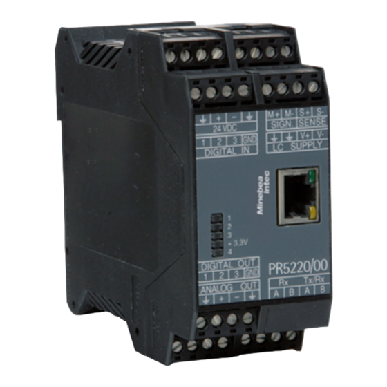
Page 26: Overview Of Connections
3 Device description Transmitter Series PR 5220 Overview of connections EN-23 Minebea Intec... -
Page 27: Device Installation
Connect to power supply. Check the installation. Mechanical preparation 4.2.1 Control cabinet units Have all required parts, technical documents and tools at hand for installation. Other procedures: Install device. Secure the cable at the place of installation; e.g.,using cable ties. Minebea Intec EN-24... -
Page 28: Emc-Compliant Installation
Connect mounting rail to protective earth. Install measure and data cables separately from power cables. Description Screen clamp (e.g. Phoenix SK8-D) Screen rail (e.g. Phoenix NLS-CU 3/10) Rail connector bracket (e.g. Phoenix AB-SK 65D) Mounting rail (35 mm) EN-25 Minebea Intec... -
Page 29: Hardware Construction
The device has an internal Ethernet port. 4.4.2.1 Ethernet port The Ethernet port contains a powerful TCP/IP interface connection with transfer rates of 10 or 100 Mbit/s. Function tests can be made via the LEDs (green and yellow) in the RJ-45 socket. Minebea Intec EN-26... - Page 30 Notebook/PC connection Remote operation of the device from a notebook/PC is possible (install VNC software version 3.3.7* on the notebook/PC). For the network address see Chapter7.7. * Minebea Intec guarantees the functionality only if this version is used. EN-27 Minebea Intec...
-
Page 31: Interface
<8/1> or 7/1 Parity Even, <odd>, none Signals TxA, RxA (R-), TxB, RxB (R+) Potential isolation Cable type Screened twisted pair (e.g. LifYCY 2×2×0.20) Cable gauge 1.5 mm Cable length max. 1000 m <…> = preset values (factory settings) Minebea Intec EN-28... - Page 32 4.4.3.1 Connecting the remote display PR 5110 The PR 5110 remote display can be connected via the RS-485 interface. Four-wire transmission, point to point connection, full duplex (simultaneous sending and receiving) is possible with the remote display. EN-29 Minebea Intec...
- Page 33 ] - [oP 13] - [SEndModE] - [SEnd] ] - [oP 14] - [WEIght] - [FolloW] ] - [oP 15] - [WPkEy] - [SElEct] The following operations are possible from the connected remote display: Readout current weight Tare Reset tare Zero Minebea Intec EN-30...
- Page 34 One IS platform with xBPI or SBI protocol can be connected via the RS-485 interface (2-wire). PR 5220/00 switch settings PR 5220/00 configuration ON: S1, S2, S3 - [Serial ports parameter]- [xBPI-Port]- [Builtin RS-485] S4 not relevant Note: For more information, see the platform scale manual. EN-31 Minebea Intec...
- Page 35 Color code Color Terminal designation Description + Supply voltage blue - Supply voltage green B Signal gray A Signal The following example shows the connection to the PR 6024/64S junction box using 4 digital load cells, type Pendeo®. Minebea Intec EN-32...
-
Page 36: Analog Outputs
Output: Function Gross/net weight or via ProfiBus Output: Range 0/4 20 mA, configurable Output: Resolution e.g. 0 20 mA in max. 40,000 parts Output: Linearity error @ 0 20 mA: <0.05% @ 4 20 mA: <0.025% EN-33 Minebea Intec... -
Page 37: Digital Inputs
The voltage level corresponds to the drop across the external 500 resistor. 4.4.5 Digital inputs Three passive opto-decoupled inputs are permanently built into the device. The interface can be configured by software. All inputs have a common GND (-). Minebea Intec EN-34... - Page 38 High: 10 28 V DC Passive, external power supply required Current ≤11 mA @ 24 V DC ≤5 mA @ 12 V DC Signals GND (-) for all inputs Potential isolation Yes, via optocoupler Cable length max. 50 m screened EN-35 Minebea Intec...
-
Page 39: Digital Outputs
If the voltage at terminals (in this example: 1-GND) is 10 V DC, input 1 is activated (true). 4.4.6 Digital outputs Three passive opto-decoupled outputs are permanently built into the device. The interface can be configured by software. All outputs have a common GND (-). Specifications Description Data Connection Terminal, 4-pin 3 outputs Minebea Intec EN-36... - Page 40 Cable length max. 50 m screened Example: Relay control (power output) * inductive load, supression diode The relay switches when the output 1 is active (true). To protect the output circuit, relays must be equipped with free-wheel diodes. EN-37 Minebea Intec...
-
Page 41: Connecting Analog Load Cells And Platforms
The colors listed here are valid for the Minebea Intecload cells and connection cables of type "PR " Color code black blue green gray white For additional information on the connection of load cells and junction boxes refer to the corresponding installation manuals. Minebea Intec EN-38... - Page 42 - Measuring voltage (load cell output) SENSE S+ + sense + Sense voltage SENSE S- - Sense - Sense voltage LC SUPPLY V+ + Supply/rd + Supply voltage LC SUPPLY V- - Supply/bu - Supply voltage Grounding Screen (ground) LC SUPPLY EN-39 Minebea Intec...
- Page 43 Load cell supply circuit Load resistance of load cell circuit ≥75 , e.g. 8 load cells of 650 each Supply voltage is fixed to 12 V DC and protected against short circuit. For further technical data, see Chapter 17.5.1. Minebea Intec EN-40...
- Page 44 Testing the measuring circuit A simple test with the load cells connected can be carried out with a multimeter. Note: With external supply or use of an intrinsically safe load cell interface the internal load cell supply is not relevant. EN-41 Minebea Intec...
- Page 45 12 V ±0.8 V (symmetrical to frame ground) Sense voltage 12 V ±0.8 V (symmetrical to frame ground) Measuring voltage 0–12 mV @ load cells with 1.0 mV/V 0–24 mV @ load cells with 2.0 mV/V Measuring voltage 0 V ±0.5 V Minebea Intec EN-42...
- Page 46 ±4 V DC. 4.4.7.8 Connecting to input/output interface PR 1626/60 Connections are made via connecting cable PR 6135/.. . The internal load cell supply voltage (V+, V-) of the PR 5220 must not be connected. EN-43 Minebea Intec...
- Page 47 Installation in explosion-hazarded areas The screen of the load cell cable and the screen of the connecting cable must not be connected inside the junction box whenever regulations governing installation in explosion-hazarded areas prohibit any connection of the two ends. Minebea Intec EN-44...
- Page 48 The cable screens must be connected to the grounding terminal of the device. If the measuring lines (+M, -M) are screened individually, these screens must be connected to the GND terminal as well (see also Chapter 4.3). EN-45 Minebea Intec...
- Page 49 Transmitter Series PR 5220 4 Device installation Example: Platform with 4-wire connection The following links between the terminal contacts are provided: ① from SIGN. SENSE S+ after LC SUPPLY V+ ② from SIGN. SENSE S- after LC SUPPLY V- Minebea Intec EN-46...
-
Page 50: Interfaces
The ProfiBus-DP interface has the type designation PR 5220/01. Communication protocols and syntax comply with the ProfiBus-DP standard to IEC 61158, with transfer rates up to 12 Mbit/s. Connection to the ProfiBus is established using the 9-pin D-Sub female connector on the front panel. EN-47 Minebea Intec... - Page 51 User Organization). Industry-compatible CE, UL and cUL Note: The GSD file is stored on the CD supplied with the device (fieldbus directory of the respective device). The current file is also available for download via the Internet. http://www.minebea-intec.com Minebea Intec EN-48...
- Page 52 Insulated voltage supply +5 V to RS-485 side not connected 8 -------------------- RxD/TxD-P (negative) ac- green Send/receive data cording to RS-485 specifi- Data core A/D (N) cation not connected Note: You can only use plug connections with integrated terminating resistors. EN-49 Minebea Intec...
-
Page 53: Devicenet Interface
Bus termination at the cable ends Bus load 33 mA @ 24 V DC Cable type DeviceNet; color: petrol green; 2x2 twisted pair; screened Cable impedance Cable length Depends on cable type and transmission rate: 100 500 m Minebea Intec EN-50... -
Page 54: Profinet I/O Interface
It contains powerful UDP/IP connecting circuitry with transfer rates of 10 or 100 Mbit/s. Specifications Description Data Transmission rate 10 Mbit/s and 100 Mbit/s Auto detection (100, FullDX) Protocol ProfiNet I/O Connection mode Network Configuration XML file "GSDML-Vx.xx-Sartorius-PR5220-2P-xxxxxx.xml" EN-51 Minebea Intec... -
Page 55: Ethernet-Ip Interface
The EtherNet-IP interfaces have the type designation PR 5220/07. It is a complete EtherNet-IP Adapter (slave) with a standard RJ-45 socket for network connection. It contains a powerful TCP/IP and EtherNet-IP interface connection with transfer rates of 10 or 100 Mbit/s. Minebea Intec EN-52... - Page 56 - [Fieldbus parameter] (see also Chapters 7.15.3 and 12.2). The EDS file is stored on the CD supplied with the device (fieldbus directory of the respective device). The current file is also available for download via the Internet. http://www.minebea-intec.com EN-53 Minebea Intec...
-
Page 57: "Standard" Application
5.1.2 Display functions Display of gross, net or tare weight Tare/reset tare Set gross to zero Display of weight values or remote display Functions via digital inputs and outputs Information interchange via serial I/O, fieldbus and network Minebea Intec EN-54... -
Page 58: Easyfill" Application
Input: tolerance values; adopt unit from the calibration. — Calming time Calming time Input: in ms — Start Start filling. — Stop Stop filling. — Restart Restart filling. — Abort Abort filling. — Configuration — Configuration mode Configure the mode EN-55 Minebea Intec... - Page 59 Tolerance above/below set point Input: tolerance values; adopt unit from the calibration. — Calming time Calming time Input: in ms — Default Reset values to 0. — Print all Print all ID entries. — Print Print selected ID entry. Minebea Intec EN-56...
-
Page 60: Commissioning
When the CAL switch is in "opened" position, the calibration data and parameters can be changed using the PC program or via the ProfiBus connection. With the CAL switch in the "closed" position, the calibration data (e.g. dead load, span) and parameters (measuring time, zero tracking etc.) cannot be changed. EN-57 Minebea Intec... - Page 61 Measure rate <160> ms Dead load <0.000000> mV/V Standstill time <1> M Span <1.000000> mV/V Standstill range <1.00> d Standstill timeout (timeout) <8> M Calibration parameter <default> Test mode <absolute> Overload (range > Max) <9>d Zero-setting range <50.00> d Minebea Intec EN-58...
-
Page 62: Restart
Via a notebook/PC using the VNC software (included on the CD) Via a notebook/PC using an Internet browser As soon as the device is provided with power, the display and/or Notebook/PC shows: Checking… The device is booting up. Booting… Restoring… EN-59 Minebea Intec... -
Page 63: Switching Off The Device
On the notebook/PC, the host names of the connected devices in the network are listed under [Network]. Double-click the host name to open the device page in the WEB browser. The IP address is displayed on the bottom right. Minebea Intec EN-60... -
Page 64: Finding And Connecting A Device With A Notebook/Pc
The "host name" is composed of the device name and the last 3 bytes of the MAC ID. A label with the complete MAC ID is located on the outside of the device. Host name: PR5220-6B6A5E For this, the program must be installed and started on a notebook/PC. EN-61 Minebea Intec... - Page 65 If the browser window remains empty after the minimum wait time, or if the expected device is not listed, the network ID of the local notebook/PC must be checked and changed, if necessary. Only certain Minebea Intec devices are supported by the "indicator browser"! Minebea Intec EN-62...
-
Page 66: Resetting The Network Address
2 3-minute waiting time. Subsequently, a network connection is established automatically (device <-> workstation/PC). Operation using VNC VNC (on the enclosed CD-ROM) stands for "virtual network computing" and is a program for remote operation of computers. EN-63 Minebea Intec... - Page 67 For direct operation using the VNC program, the IP address (extended by :1) must be specified when you run the program, e.g., 172.24.20.233:1. Note: In the device, the VNC access to certain notebooks/PCs can be limited, see Chapter 7.15.4. The VNC-user interface is displayed. Minebea Intec EN-64...
-
Page 68: Operation Via A Web Browser
If the WEB menu and the device view are required, the [Remote Configuration (VNC) Popup Window] menu item must be selected in order for two windows to be opened and the VNC viewer always remains open, even if individual menu items are selected in the WEB menu. 7.11 System setup EN-65 Minebea Intec... -
Page 69: Serial Ports Parameter
Subnet mask, display: Mask for valid IP address range — Default gateway Standard gateway, display: IP number for gateway — Remote access Remote access to VNC client — VNC client Access restriction, Input: authorized client for instrument operation Minebea Intec EN-66... -
Page 70: Weighing Points
Selection: below or equal 8 V (≤8 V), <above 8 V> (>8 V) — Fcut Input of cut off frequency, only unless filter not "off", 0.1–80.0 Hz — Test mode Selection for display of the deviation from the test value: <Absolute>, relative EN-67 Minebea Intec... - Page 71 (impossible when [Range mode] "Multi- interval" has been selected or Max has more than 3 decimals), NSC, NTEP Note: Transmitters of the PR 5220 series are not approved for calibration. — Standstill time Input of the standstill period: 0.01 s <0.50 s>...
- Page 72 Number of weight units: 1 weight unit, 2 weight units, 3 weight units — Weight unit 1…3 Chose weight unit 1…3: Gramm [g], Kilogram [kg], Carat [ct], Pound [lb], ounce [oz], Troy ounce [ozt], Tael Hongkong [tlh], Tael EN-69 Minebea Intec...
- Page 73 (odd parity) — Stop bits Selection: <1>, 2 7.11.5.3 "Pendeo® Truck/Process" weighing point — Assign Assignment of the Pendeo scale Type, number of load cells, serial number of each load cell and weighing point serial number Minebea Intec EN-70...
- Page 74 — Standstill time Input of the standstill period: 0.01 s <0.50 s> 2.0 s (The range depends on the measuring time.) — Standstill Input of the standstill range: 0.00 d <1.00 range d> 10.00 d (The range depends on the measuring time.) — Tare timeout EN-71 Minebea Intec...
- Page 75 — LC name Change the display from [ID] (LC 1…n + serial number) to [by name] of the load cells; only possible if a load cell name has been assigned. Minebea Intec EN-72...
-
Page 76: Limit Parameter
— Output on error Output on error: 0 mA = set to 0 mA, <4 mA> = set to 4 mA, 20 mA = set to 20 mA, hold = last output value remains unchanged — Output if <0 EN-73 Minebea Intec... -
Page 77: Calibrating Internal Weighing Point
7.12 Calibrating internal weighing point 7.12.1 General information Transmitters of the PR 5220 series are not approved for calibration. The legal-for-trade application of PR 5220 with other device has to be verified. The calibration data are protected by the CAL switch (see Chapter 7.1.3.1). -
Page 78: Selecting The Calibration Mode
Selecting the calibration mode Note: The [Modify] menu item is only used for small changes (e.g.changing the dead load/ preload, changing the mV/V values for dead load/preload and/or Max, changing the scale interval). Otherwise select the [New] menu item. EN-75 Minebea Intec... - Page 79 3. By pressing [Continue] the data are reset to default first (default) before performing calibration. Press [Cancel] to cancel selection. 4. Determining the maximum load [Max], see Chapter 7.12.4. 5. Determining the scale interval [Scale interval], see Chapter 7.12.5. 6. Determining the dead load [Deadload at], see Chapter 7.12.6. Minebea Intec EN-76...
- Page 80 4. Either press the [by mV/V] softkey to enter the value again or clear the scale/hopper and press the [by load] softkey to reset the dead load. 5. Press to exit the calibration. A prompt window opens. EN-77 Minebea Intec...
-
Page 81: Setting Maximum Load
Max weight value from 0.00010 to 999999 in t, kg, g, mg, lb or oz. Maximum weight value must be an integer multiple of the scale interval (1 d). It may have up to 6 digits and is entered as a numeric value with or without a decimal point. Minebea Intec EN-78... -
Page 82: Determining The Scale Interval
Calculation for scale interval for Max (automatic): d = Max/scale interval (1 d) = 6000 kg/2 kg = 3000 Procedure: The weight unit is taken from [Max]. The number of digits behind the decimal point is also automatically determined when [Max] is entered. EN-79 Minebea Intec... -
Page 83: Determining The Dead Load
Only deleting of the linearization points deactivates the linearization mode! To use the empty scale/hopper as dead load (normal case): Clear the scale/hopper. 2. Press the [by load] softkey. 3. Confirm entries with The verification is displayed by "Setting dead load…". Minebea Intec EN-80... -
Page 84: Calibrating With Weight
Changes cannot be made while linearization is switched on. Only deleting of the linearization points deactivates the linearization mode! Press the [by load] softkey. 2. Place the CAL weight on the scale. 3. Enter the weight of the CAL weight. 4. Confirm the entries. EN-81 Minebea Intec... -
Page 85: Calibrating With Mv/V
Calculating SPAN value for Max and, if necessary, for the dead see Chapter 7.12.8.1. 2. Press the [by mV/V] softkey. 3. Entering the SPAN value for Max and, if necessary, for the subsequent correction of dead load (see Chapter 7.12.10). Minebea Intec EN-82... - Page 86 Normally, calculation of the dead load (scale without load/empty hopper) is not necessary. Subsequent dead load correction (as described in Chapter 7.12.8.1) can be used for later re-determination of the dead load, when the scale/hopper is empty. EN-83 Minebea Intec...
-
Page 87: Calibrating With Load Cell Data (Smart Calibration)
Calibrating with load cell data (smart calibration) If the scale is not used in legal metrology, calibration without weights can be performed. The easiest method is the one using load cell data without calculation. Press the [by data] softkey. Minebea Intec EN-84... -
Page 88: Subsequent Dead Load Correction
If the hopper/platform weight changes by an amount that is higher than the zero-setting range; e.g.due to dead load reduction, dead load increase, or mechanical changes, the functions for automatic zero tracking and manual zero setting no longer work. EN-85 Minebea Intec... -
Page 89: Linearization
Changes cannot be made while linearization is switched on. Only deleting of the linearization points deactivates the linearization mode! 7.12.11 Linearization The measurement range for a straight can be optimized by setting the linearization points. Requirements: Calibration of Max and dead load was done. Minebea Intec EN-86... - Page 90 2. Press the [Add] softkey to set a linearization point. The input window opens. 3. Enter the desired value using the keyboard. 4. Press the [Ok] softkey. 5. Repeat these steps to set up to three linearization points in succession. EN-87 Minebea Intec...
- Page 91 The value corresponding to the weight is automatically entered in mV/V. 7. Repeat these steps to automatically enter the corresponding values for the weights of all set linearization points in mV/V. 8. Press to switch to the previous window. Minebea Intec EN-88...
-
Page 92: Calculating The Test Value
-[Weighing point]- [Calib]- [Param]- [Test mode] the following is displayed by calling the Test with the key later on: with [Absolute] the maximum load with [Relative] the deviation from the test value 7.12.13 Saving the calibration Quit calibration by pressing the softkey. EN-89 Minebea Intec... -
Page 93: Cancelling A Calibration
After finishing the calibration, set the CAL switch to the closed position; see also Chapter 7.1.3.1. 7.12.14 Cancelling a calibration Quit calibration by pressing the softkey. You are prompted to confirm whether calibration should be closed without determining the test value. Minebea Intec EN-90... -
Page 94: Parameter Input
If you press [Undo], changes are not saved and the display returns to the selection menu for the weighing points. Leaving the menu is displayed by "Exit calibration". 7.12.15 Parameter Input The menu is accessible via -[Weighing point]- [Calib]- [Param]. EN-91 Minebea Intec... - Page 95 [Measuretime]: <160 ms [Digital filter]: aperiod. [Fcut]: 2.00 Hz [Fcut] This line only is shown if the digital filter is switched on. The smaller the cut-off frequency, the slower the measurement and the more stable the measurement result. Minebea Intec EN-92...
- Page 96 Define a ±range around the zero point determined by the dead load during calibration; within this range the displayed gross weight can be set to zero by pressing the zero-setting key (or by a corresponding external command), and automatic zero tracking is active. Setting range: 0.00 10000.00 d EN-93 Minebea Intec...
- Page 97 ≤0.25 d of range 1, the scale is stable and not tared, the scale returns to range 1 with the corresponding scale interval. Note: During calibration, the multiple range function is always switched off. Example: Range mode: "Multiple range" Minebea Intec EN-94...
- Page 98 The weight display header includes the current interval range (R1, R2, or R3), Max, Min, and d (or e with instruments used in legal metrology) (Example: multi-interval scale in range 2): The parameters [Range limit 1] and [Range limit 2] are the interval ranges. EN-95 Minebea Intec...
-
Page 99: Calibrating Xbpi-Scale
4. Setting interval range 2: Enter "2900 kg" for range limit 2. 5. Press the softkey to exit and save calibration. 7.13 Calibrating xBPI-scale 7.13.1 General information The legal-for-trade application of PR 5220 with a xBPI-scale is not possible. Minebea Intec EN-96... -
Page 100: Parameters For Serial Interface
3. Press the [Param] softkey. The following window opens: 4. If necessary, change the parameters. Only the "baudrate" and "stop bits" can be set for an xBPI scale. 5. Press to exit the menu and to save the settings. EN-97 Minebea Intec... -
Page 101: Parameters For The Xbpi-Weighing Function
With serial number "0", checking is omitted. Setting range: 0 99999999 [SBN Address] When the address is not set to 0, bus operation is active. Possible addresses: 1–31, i.e., max. 31 xBPI scales can be operated on an RS-485 branch. Minebea Intec EN-98... -
Page 102: Setting Up An Xbpi Platform
The parameters of the xBPI-scale are read into the device. Ticks indicate the progress. An error message is displayed if communication with the xBPI scale is not possible! The following window opens: 3. Select [Show device info] with the cursor and confirm. The following window opens: EN-99 Minebea Intec... - Page 103 Only the parameters supported by the connected scale are displayed. 12. Press the softkey to exit the menu and to save the settings. A prompt window opens. 13. Press the [Yes] softkey to save the data. Press [No] for exit from the menu without data change. Minebea Intec EN-100...
-
Page 104: Xbpi-Parameter Tables
— Stable conditions — Unstable cond. — Very unstable cond. — Application/Filter — standard mode — manual filling — automatic dosing — checkweighing — Stability range — 0.25 digit — 0.5 digit — 1 digit — 2 digits EN-101 Minebea Intec... - Page 105 — only for zeroing — Measure rate — normal output — fast output — Calibration check — Off — Calibration prompt — External adjustment — Accessible — Blocked — Maximum capacity — reduced by preload — constant Minebea Intec EN-102...
- Page 106 — three levels lower — 1% — 0.5% — 0.2% — 0.1% — 0.05% — 0.02% — 0.01% — Multi interval — increased by 10 7.13.5.3 Interface parameters [Interface settings] — Communication type — SBI protocol — xBPI protocol EN-103 Minebea Intec...
-
Page 107: Setting The Xbpi Dead Load
— after 50 updates — after 100 updates — Parameter change — can be changed — cannot be changed 7.13.6 Setting the xBPI dead load Note: For Minebea Intec both terms "dead load" and "preload" are used. Minebea Intec EN-104... - Page 108 The parameters of the xBPI-scale are read into the device. Ticks indicate the progress. An error message is displayed if communication with the xBPI scale is not possible! The following window opens: 3. Select [Calibration] with the cursor and confirm. The following window opens: EN-105 Minebea Intec...
-
Page 109: Xbpi Calibration With User Specified Weight
The calibration process is carried out without a weight. The calibration status is displayed. 5. Place the weight on the scale. The deviation is displayed in the last line with increased resolution (10-fold). 6. Press the [Accept] softkey. The data are saved and the instrument returns the following message: Minebea Intec EN-106... -
Page 110: Xbpi Calibration With Automatic Weight Detection
The parameters of the xBPI-scale are read into the device. 3. Select [Calibration]- [Adjust with auto weight] with the cursor and confirm. The calibration process is carried out without a weight. The calibration status is displayed. The weight is specified automatically. EN-107 Minebea Intec... -
Page 111: Xbpi Calibration With Default Weight
4. Place the displayed weight on the scale. The deviation is displayed in the last line with increased resolution (10-fold). 5. Press the [Accept] softkey. The date are saved. The weight is displayed in high-resolution (10x). 6. Remove the weight. Minebea Intec EN-108... -
Page 112: Xbpi Calibration With Built-In Weight
The measurement range for a straight can be optimized by setting the linearization points. The following describes standard linearization. Requirements: The xBPI protocol has been selected (see Chapter 7.13.2). The "xBPI-scale" weighing point has been selected (see Chapter 7.13.3). The platform has been set up (see Chapter 7.13.4). EN-109 Minebea Intec... -
Page 113: Calibrating Digital Load Cells Of Type "Pendeo
7.14 Calibrating digital load cells of type "Pendeo" 7.14.1 General information The digital load cells have been calibrated at the factory based on the acceleration of gravity at Hamburg (9.81379 m/s ). The calibration data in the load cells are invariable. Minebea Intec EN-110... -
Page 114: Selecting And Configuring Rs-485 Interface
The available interfaces are visible under -[Show HW-slots]. 7.14.2 Selecting and configuring RS-485 interface Select -[Serial ports parameter]- [xBPI-Port] and confirm. The following window opens: 2. Select the desired interface and confirm. 3. Press the [Param] softkey. The following window opens: EN-111 Minebea Intec... -
Page 115: Selecting The Load Cell Type
During calibration, no data is changed in the digital load cells. The calibration data and parameters are saved in the instrument. The unique serial numbers of the connected load cells are monitored. For the calibration the following order must be followed: Search for load cells, see Chapter 7.14.5. Minebea Intec EN-112... -
Page 116: Searching Load Cells
Perform a corner correction if necessary; see Chapter 7.14.10.3. Note: For further information about calibrating weighing points, see Chapter 7.12.3. 7.14.5 Searching load cells Select -[Weighing point]- [Weighing point A]. 2. Press the [Assign] softkey. The following window opens: 3. Press the [Search] softkey. EN-113 Minebea Intec... -
Page 117: Assigning Load Cells
The load cells (serial number) can be assigned to the place of installation in this menu. This is important for correcting the dead load (distribution to the individual load cells), for corner correction and in the event of load cell replacement. An example of a possible assignment is shown below. Minebea Intec EN-114... - Page 118 7. Remove the weight. 8. Repeat these steps for load cells 2 4. 9. Press the [Accept] softkey. 10. Press the softkey to exit the menu and save. 11. Press the [View] softkey. The new assignment will be displayed. EN-115 Minebea Intec...
-
Page 119: Calibrating Load Cells
[Number of platforms] (only for Pendeo Truck-load cell) This parameter is shown only in the case of 8 load cells. Entering the number of platforms. [Number of vessel feet] (only for Pendeo Process-load cells) Enter the number of vessel feet. Minebea Intec EN-116... - Page 120 During calibration the weight can be displayed with 10 fold resolution by pressing key. After 5 seconds the display returns to normal resolution. Press if you want to switch to normal resolution immediately. 5. Press the softkey to exit the menu. EN-117 Minebea Intec...
-
Page 121: Assigning Load Cell Names
Item number, serial number, dead load and current weigh of connected load cells are displayed. 7.14.9.1 Deactivating the load cell A load cell can be deactivated if it is defective. The weight is then distributed to the remaining load cells. Minebea Intec EN-118... -
Page 122: Corner Correction
After inserting and connecting the new load cell, select the line of the deactivated load cell and confirm. 2. Press the [Accept] softkey. A search process is started and only then is the new load cell detected. 7.14.10 Corner correction EN-119 Minebea Intec... - Page 123 7. If all load cells have been loaded one time, press the [Calc] softkey to perform the corner correction. The total weight remains unchanged. Only the effect of the individual load cells is corrected. When corner correction is completed, it is marked with "OK". 8. Press to exit the menu and save. Minebea Intec EN-120...
-
Page 124: Terminating/Saving Calibration
5. After finishing calibration, set the CAL switch to the closed position; see Chapter 7.1.3.1. 7.14.12 Parameter Input The menu is accessible via - [Weighing point] - [Weighing point A] - [Assign] - [Calib] - [Param] . EN-121 Minebea Intec... - Page 125 The input is done as seconds. Valid range: 0.0 <2.5> 25 s. At 0.0 s taring is only carried out when the scale is already stable. Minebea Intec EN-122...
-
Page 126: Subsequent Dead Load Correction
If the hopper/platform weight changes by an amount that is higher than the zero-setting range; e.g.due to dead load reduction, dead load increase, or mechanical changes, the functions for automatic zero tracking and manual zero setting no longer work. EN-123 Minebea Intec... -
Page 127: Displaying Weighing Point Serial Number
Serial interfaces [Serial ports parameter] Operating parameter [Operating parameter] Fieldbus parameter [Fieldbus parameter] Network parameter [Network parameter] Configuring limits [Limit parameter] Note: This menu item is only available if under -[Operating parameter]- [Application] "Standard" has been selected. Minebea Intec EN-124... -
Page 128: Selecting And Configuring Serial Interfaces
"Standard" has been selected. Configuring analog output [Analog output parameter] 7.15.1 Selecting and configuring serial interfaces The interfaces are configured under this menu item. Select - [Serial ports parameter] and confirm. The following window opens. 7.15.1.1 Remote display protocol EN-125 Minebea Intec... - Page 129 The selected interface is displayed. 3. Press the [Param] softkey to set the parameters. The following window opens: 4. Select [Baudrate] and confirm. A selection window opens. 5. Select the desired transmission speed and confirm. 6. Select [Mode] and confirm. Minebea Intec EN-126...
- Page 130 7.15.1.2 ModBus RTU protocol Select [ModBus-RTU] and confirm. A selection window opens. 2. Select the desired interface and confirm. The selected interface is displayed. 3. Press the [Param] softkey to set the parameters. EN-127 Minebea Intec...
- Page 131 9. Enter and confirm the slave address (in this case: 65). 10. Press 2× to exit the menu and save. 7.15.1.3 SMA protocol Select [SMA] and confirm. A selection window opens. 2. Select the desired interface and confirm. The selected interface is displayed. Minebea Intec EN-128...
- Page 132 A selection window opens. 5. Select the desired transmission speed and confirm. 6. Press two times to exit the menu and save. 7.15.1.4 xBPI protocol Select [xBPI-Port] and confirm. A selection window opens. 2. Select the desired interface and confirm. EN-129 Minebea Intec...
-
Page 133: Operating Parameters
A selection window opens. 7. Select the desired stopbit and confirm. 8. Press two times to exit the menu and save. 7.15.2 Operating parameters The operating parameters are set under this menu item. Open the menu via -[Operating parameter]. Minebea Intec EN-130... - Page 134 (around the zero-point set with the dead load) is already utilized due to a previous zero-setting operation and/or automatic zero setting. The setting to zero is deactivated by [disabled]. Press to return to the Setup menu. The following prompt window appears if parameters were changed. EN-131 Minebea Intec...
-
Page 135: Fieldbus Parameters
The protocol displayed automatically depends on the device version : [ProfiBus-DP] for PR 5220/01 [InterBus-S] for [DeviceNet] for PR 5220/04 [ProfiNet I/O] for PR 5220/06 [EtherNet-IP] for PR 5220/07 Example: PR 5220/06 ProfiNet I/O Note: The individual parameters depend on the fieldbus type. Minebea Intec EN-132... - Page 136 See Chapter "Description of the I/O Area" Example: The gross weight should be read. I/O size = 8 bytes, counted from byte 0–7 7.15.3.2 DeviceNet settings for Rockwell workstation Requirements: PR 5220/04 DeviceNet is installed. The parameters are selected and saved. EN-133 Minebea Intec...
- Page 137 2. Enter the IP address and network mask under - [Fieldbus parameter] and confirm. 3. Load the file "GSDML-Vx.xx-Sartorius-5220-2P-xxxxxx.xml" from CD and install it in the development environment. 4. Add the PR 5220 device to the project and assign the I/O ranges. Minebea Intec EN-134...
-
Page 138: Network Parameters
The gross weight should be read. I/O size = 8 bytes, counted from byte 0–7 7.15.4 Network parameters Under this menu item, you can define the network parameters for the network connections (built-in LAN adapter). Open the menu via - [Network parameter]. EN-135 Minebea Intec... - Page 139 Access via VNC not permitted. VNC client 172.24.21.101 Access only from client machine with this address. VNC client 172.24.21.255 Access from any client with address within range 172.24.21.1 - ..254. VNC client 255.255.255.255 Access from client with any address. Minebea Intec EN-136...
-
Page 140: Configuring Limit Values
[Configuration] - [Application settings] - [Number of units] "1 Weight" Define the parameters for limits under -[Limit parameter]. For the configuration the following order must be followed: 1. Define limits. 2. Define an action. 3. Determine a condition. 4. Save parameters. EN-137 Minebea Intec... - Page 141 If the Limits 1 and 2 are the same for "On" and "Off" (on = off), switches output 1 (Limit 1 out) ON if the weight (Wgt) exceeds the value. switches output 2 (Limit 2 out) OFF if the weight falls below the value. Minebea Intec EN-138...
- Page 142 The limit values can be assigned to the outputs directly in the I/O parameters. Markers can be set for all limits (in this case, see Example 2): Highlight and confirm the action line of the appropriate limit using the cursor. EN-139 Minebea Intec...
- Page 143 Weight not within zero-setting range standstill X38 = 0 Standstill not active X39 = 0 Weight not below zero or above Max command error X48 = 0 For internal use only. command busy X49 = 0 For internal use only. Minebea Intec EN-140...
- Page 144 Instrument is tared. marker bit 1 X64 = 1 Marker bit 1 set, after power-on the markers are set to "0". marker bit 2 X65 = 1 Marker bit 2 set, after power-on the markers are set to "0". EN-141 Minebea Intec...
-
Page 145: Configuring Digital Inputs
An action both for signal change from 0 to 1 (on) and from 1 to 0 (off) can be determined for each of the three inputs. Digital inputs can be linked with conditions that must be met before an action can be started. The parameters for the digital inputs are defined under -[Digital i/o parameter]. Minebea Intec EN-142... - Page 146 X118 = 1 Set fixtare (use the value in address D31 as a tare value) get fixtare X119 = 1 Save gross value as fixtare in address clr marker 1 X64 = 0 Clear marker 1 EN-143 Minebea Intec...
- Page 147 0 to 1 (on) or for signal change from 1 to 0 (off). The condition is selected from the list in Chapter 7.15.5.3. No condition is defined when selecting [no condition]. The action is executed directly. Minebea Intec EN-144...
-
Page 148: Configuring Digital Outputs
SPM Bit Description no condition No condition actual diginp1 X00 = 0 digital input 1: not active actual diginp2 X01 = 0 digital input 2: not active actual diginp3 X02 = 0 digital input 3: not active EN-145 Minebea Intec... - Page 149 ADC error X32 = 1 General error in the weighing point above Max X33 = 1 Weight above Max overload X34 = 1 Weight above Max plus the 'overload' value below zero X35 = 1 Weight below zero Minebea Intec EN-146...
- Page 150 Function is active and output is not active (e.g.: if "overload" is reached, a lamp goes out). The parameters for the digital outputs are defined under -[Digital i/o parameter]. Note: This menu item is only available if under -[Operating parameter]- [Application] "Standard" has been selected. Example: EN-147 Minebea Intec...
- Page 151 3. Select [Output 2] and confirm. A selection window opens. Output 2 [Output 2] remains (active), as long as the weight is not above Max (X33=0). 4. Select [above MAX] and confirm. 5. Select [Output 3] and confirm. A selection window opens. Minebea Intec EN-148...
-
Page 152: Configuring Analog Output
Configuring analog output The weight value of the weighing point is transmitted to the output. Define the parameters for the analog output under -[Analog output parameter]. The analog output can be configured according to the table below. EN-149 Minebea Intec... -
Page 153: System Information
Quit the menu and save parameters by pressing Note: Adapting the analog output, see Chapter 9.1.2.1. 7.16 System information This menu displays system information. You can also check inputs and outputs, see Chapter 9.1.2.2. Press to access the menu. Minebea Intec EN-150... -
Page 154: Displaying The Version
Version number and firmware creation date [PRxxxx-Application] Version number and application creation date [BIOS] Version number and BIOS creation date [Board number] Nine-digit board number 2. Press to return to the previous window. 7.16.2 Displaying the status EN-151 Minebea Intec... -
Page 155: Showing Hardware Options
[Free system RAM] Free working system memory space [CAL switch] Status display [opened] = opened, no write protection. [closed] = closed, write protection is active. 2. Press to return to the previous window. 7.16.3 Showing hardware options Minebea Intec EN-152... -
Page 156: Displaying Pendeo Data
The tool tip displays the version number. 5th line Standard interface, weighing electronics The tool tip displays the weighing point serial number and manufacturing date of the factory. 2. Press to return to the previous window. 7.16.4 Displaying Pendeo data EN-153 Minebea Intec... - Page 157 [LC 1…n] Bar graph display The bar graph shows three areas: dead load (can be changed by calibration) Maximum capacity E (max. capacity of load cell) including dead load (load cell, cannot be changed) Minebea Intec EN-154...
- Page 158 Max. resolution Minimum LC verification Minimum preload signal recurrence Overload Weight value above max. load Overload counter Number of weight values above max. load The higher the number, the higher the probabi- lity of a faulty load cell. EN-155 Minebea Intec...
- Page 159 Max. temperature Max. measured temperature Min. temperature Min. measured temperature Max. weight value at Date and time display Time of largest load on load cells Max. weight value Display 3. Press to return to the previous window. Minebea Intec EN-156...
-
Page 160: Production
There are hard drives for 10 material data records available, which are retained after a power failure. It is important to save material data. Starting the application Requirements: The "EasyFill" application has been selected; see Chapter 7.15.2. Procedure: Press the [Start] softkey. The menu opens. EN-157 Minebea Intec... -
Page 161: Configuration Via A Notebook/Pc
The following modes are configured under the [Configuration mode] menu item: Filling mode Interaction mode Select [Configuration mode] and confirm. 2. Select [Dosing mode] and confirm. A selection window opens. 3. Select the desired filling mode (see Chapters 8.3.1.1 and 8.3.1.2) and confirm. Minebea Intec EN-158... - Page 162 7. Press the [Yes] softkey to save the changes. 8.3.1.1 Net filling (B1) The scale is tared and then the amount listed in the process line is automatically added (coarse/fine). A fixed overshoot value is configured. Net = gross - tare EN-159 Minebea Intec...
- Page 163 8.3.1.2 Net decrease (B4) The scale is automatically discharged up to the specified value. The other parameters and the process correspond to the "Net filling" mode; see Chapter 8.3.1.1. Net = gross - tare Tare = gross Minebea Intec EN-160...
-
Page 164: Configuring Digital Inputs And Outputs
SPM addresses are assigned to the digital inputs and outputs under the [Configuration digital IOs] menu item. Note: The selected SPM address must be unique within the system. The SPM addresses for the input and outputs are unchanged after a restart. EN-161 Minebea Intec... - Page 165 3. Select inputs 1 3. Use the keypad to enter and confirm a corresponding SPM address %MXxxx (see Chapter 13.4). Note: The SPM address %MX for an unused digital input = 0. 4. Press to exit the window and to save the changes. Minebea Intec EN-162...
-
Page 166: Configuring Material
The SPM address %MX for an unused digital output = 0. 7. Press to exit the window and to save the changes. 8.3.3 Configuring material The materials (products) 1 10 are configured under the [Configuration material] menu item. EN-163 Minebea Intec... - Page 167 An error message appears if the parameters for the selected material do not match the parameters of the current calibration. 2. Press the [OK] softkey. 3. Press the [Default] softkey. All values are reset. 4. Enter the material name and values using the keypad and confirm. Minebea Intec EN-164...
- Page 168 [+/- tolerance] Input: Tolerance above/below set point [Calming time] Input: Calming time 5. Configure additional materials if necessary. 6. Press to exit the window. A prompt window opens. 7. Press the [Yes] softkey to save the changes. EN-165 Minebea Intec...
-
Page 169: Filling
The production window appears. 2. Select material ID [ID 2]. 3. Press the [Start] softkey. The material (product) is filled. Press the [Stop] softkey to stop the process. You can then press the [Restart] softkey to restart the process. Minebea Intec EN-166... - Page 170 8 Production Transmitter Series PR 5220 4. Once the set point is reached, the [Start] softkey can be pressed again. 5. Press 2× to exit the application. EN-167 Minebea Intec...
-
Page 171: Extended Functions
Plug the test connector (see Chapter 18.2) into the RS-485 interface. 2. Place the switch in the proper position, see Chapter 18.2. 3. Select and confirm the desired interface. The results are displayed: passed = ok failed (no data) = error Minebea Intec EN-168... -
Page 172: Inputs And Outputs
(display). "Internal" Active PLC: The entered input values are sent to the PLC (application). The PLC output is displayed (display). The physical inputs and outputs of the system (plant) are deactivated and passive (in secured condition). EN-169 Minebea Intec... - Page 173 The output current can be adapted in small ranges. This is required, if small deviations from the nominal value occur in a connected PLC. Open the menu with - [HW-Slots]. Select and confirm the analog output. 2. Press the [Adjust] softkey. The window for the 1st value opens. Minebea Intec EN-170...
- Page 174 4. Enter and confirm e.g.the value for 20 mA measured by the connected PLC under [Measured]. A prompt window opens. 5. Press the [Yes] softkey to save the settings. If applicable, press the [No] softkey to keep the original values. The following window opens: EN-171 Minebea Intec...
- Page 175 If applicable, press the [No] softkey to keep the entered values. 8. Press to return to the previous window. 9.1.2.2 Digital inputs and outputs Open the menu with - [HW-Slots]. Select and confirm the appropriate line. The following window opens. Minebea Intec EN-172...
- Page 176 An info window is shown briefly. The "Internal" test mode is active. The inputs are simulated to test the functionality of the PLC (application); see Chapter 9.1.2. 4. Press to return to the previous window. 5. Press the [Stop PLC] softkey. An info window is shown briefly. EN-173 Minebea Intec...
-
Page 177: Functions Via The Web Site
The device name entered under -[Network parameter]- [Hostname] is shown under the header in brackets. [Remote Configuration (VNC)] Operation using the VNC program, see Chapter 7.9. [Remote Configuration (VNC) Pop-up Window] Operation using the VNC program, see Chapter 7.9. Minebea Intec EN-174... -
Page 178: Displaying Weighing Points In A Table
WEB menu. 9.2.3 Configuration printout With the [Configuration Printout] menu item the configuration of the device of the device can be displayed, saved and printed out. Click the [Configuration Printout] menu item in the WEB menu. EN-175 Minebea Intec... - Page 179 The configuration of the device is shown on the display. 2. Click on [File]- [Save as ]. 3. Create and open the required directory e.g.on the notebook. 4. Click on [Save] to save the text file in the relevant directory. Minebea Intec EN-176...
-
Page 180: Log Files
With the [Logfiles] menu item the logfiles of the device can be displayed, saved and printed out. Click the [Logfiles] menu item in the WEB menu. A list of logfiles is shown on the display. 2. Click on the desired file. EN-177 Minebea Intec... -
Page 181: Screenshots
With the [Screenshot] menu item a screenshot of the device can be displayed, saved and printed out. Click on the [Screenshot] menu item in the WEB menu. The current device display is shown as a screenshot. 2. Press the right mouse button. Minebea Intec EN-178... -
Page 182: Error Log
With the [Show error Log] menu item the error log of the device can be displayed, saved and printed out. Click the [Show error Log] menu item in the WEB menu. The error log of the device is shown on the display. EN-179 Minebea Intec... -
Page 183: Configuration Data
The configuration and calibration data of the EAROMs can be saved for back-up on the Notebook and downloaded, if necessary. Click the [Backup of Earom] menu item in the WEB menu. The backup/restore menu is shown on the display. Minebea Intec EN-180... -
Page 184: Resetting The Device To The Factory Settings
7. Close the CAL switch. Resetting the device to the factory settings Note: Reset to the factory settings is possible only, when the CAL switch is open. The IP address and the Hostname remain unaffected. Click on 2. Click on EN-181 Minebea Intec... -
Page 185: Updating New Software With Flashit
Updating with a fixed IP address Requirements: Device and notebook/PC are connected to a network/each other. The automatic address assignment "DHCP" is deactivated in the device and in the notebook/PC, see Chapter 7.15.4. Notebook/PC is set to a fixed IP address. Minebea Intec EN-182... - Page 186 IP address which has the same address range given by the subnet mask. Example: PR 5220: IP address 192.24.22.1 Notebook/PC: IP address 192.24.22.2 Device and notebook/PC have the subnet mask 255.255.255.0. 4. Enter the corresponding subnet mask. 5. Press to exit the window and to save the changes. EN-183 Minebea Intec...
- Page 187 The first three LEDs blink in a pattern on the device for 30 seconds. 4. Press the reset key (1) on the device a short time, within these 30 seconds using a pen tip or paper clip with a diameter of 1.0mm. Minebea Intec EN-184...
- Page 188 As soon as software loading is completed the device will be re-started. 5. Load next file, as described. Note: If the device cannot start because the software has not loaded correctly, the first three LEDs blink in a pattern to prompt an update. EN-185 Minebea Intec...
-
Page 189: Modbus Protocol
2: Limit 2 1: Limit 1 M: Weight is stable (standstill). R: Weight within zero-setting range Z: Weight within ¼d of 0 Write data Bit address Value in 32-bit integer format W100 Zero device: Write value 256 Minebea Intec EN-186... - Page 190 10 ModBus protocol Transmitter Series PR 5220 Bit address Value in 32-bit integer format W101 Tare device: Write value 256 Reset the tare of the device: Write value 512 EN-187 Minebea Intec...
-
Page 191: Sma Protocol
<LF> = 0A hex and ending with <CR> = 0D hex. The transmitter sends a reply on each received command after approx. 100 µs. With commands that wait for standstill of the weight value, the reply can be delayed by the timeout. Minebea Intec EN-188... -
Page 192: Fieldbus Interface
2× 8‑byte data windows. The interface protocol runs under the fieldbus and manages the access to a multitude of different data. The protocol described below is independent of the selected fieldbus; it is explained as seen from the fieldbus master. EN-189 Minebea Intec... -
Page 193: Write Window (Input Area)
The type of the register number of the data is written in byte 5. In direct access, the bits in bytes 6 and 7 are independent of the write value data type. The command is executed after a 0-1 transition of the corresponding bit. Minebea Intec EN-190... -
Page 194: Read Window (Output Area)
Now the value is available in bytes 0 to 3. 12.2.3.2 Writing data Procedure: Wait until Write_Active = 0 in the read window (ready to receive new data). 2. Write the value in bytes 0 to 3. 3. Write the register number in byte 5 (Write_Value_Select). EN-191 Minebea Intec... -
Page 195: Description Of The I/O Area (Read/Write Window)
The test operating mode is started. Now the test value can be read out by reading the gross weight. ResTare Tare is reset. SetTare Tares the scale. SetZero The scale is set to zero. Res M1 3 Marker 1 3 is reset. Minebea Intec EN-192... - Page 196 The error number can be read at Last error. It is set only if an action is executed. Tare_Active The scale has been tared. Cal_Active The device is/was configured. When this bit is 1, the scale parameters (EXPO/UNIT/STEP) must be read again. Set after "Power on" and reset after reading the FSD. EN-193 Minebea Intec...
- Page 197 Write_Value_Select together with the data. Execution is indicated by the Write_Active bit in the output area. Action of the master Reaction of the PR 5220 Write value to Write_Value. Write register number to Write_Value_Select. Write Write_Value to the selected re- gister. Minebea Intec EN-194...
- Page 198 When an action taking a longer time was started, the end of execution can be waited for after starting (see Chapters 12.2.4.3 and 12.2.4.5). Action of the master Reaction of the PR 5220 For setting bits, see Chapters 12.2.4.3 and 12.2.4.5. EN-195 Minebea Intec...
- Page 199 Bit 1 Bit 0 The master waits until value 8 is reflected in Read_Value_Selected (byte 4) of the output area. Output area Byte Name Description Gross value Gross value Gross value Gross value Gross weight request detected Status Minebea Intec EN-196...
-
Page 200: Special Hints For Devicenet And Ethernet-Ip
Register 1: Scale status (Read) Dynamic status Bit 7 Bit 6 Bit 5 Bit 4 Bit 3 Bit 2 Bit 1 Bit 0 Byte 0 STND INZSR CZERO BELOW0 >Max ADUERR Byte 1 Byte 2 PowerFail ActionAc- CmdError tive EN-197 Minebea Intec... - Page 201 Set after "Power on" and reset after reading the FSD. TareActive The instrument was tared. 12.2.6.3 Register 2: State of state-controlled action bits (Read) Signal state Bit 7 Bit 6 Bit 5 Bit 4 Bit 3 Bit 2 Bit 1 Bit 0 Minebea Intec EN-198...
- Page 202 One byte for the scale interval; content in decimal form: 0 255 1 = scale interval "1" 2 = scale interval "2" 5 = scale interval "5" 10 = scale interval "10" 20 = scale interval "20" EN-199 Minebea Intec...
- Page 203 Current gross value Register 9 Current net value, if tared; otherwise gross Register 10 Current tare value, if tared, otherwise 0 Register 11 Value in the front readout Register 12 Reserved Register 13 Reserved Register 14 Max (FSD) Minebea Intec EN-200...
- Page 204 Register 86 SetFixTare Taring with weight in numerical address D 31 "Fixtare." Register 87 GetFixTare The current gross weight is copied into numeri- cal address D31. Register 89 ResetError The CmdError error bit is reset. EN-201 Minebea Intec...
-
Page 205: Filling Protocol (64-Byte) For The "Easyfill" Application
In contrast to the 8-byte interface, in the 64-byte interface the parameters, statuses, and values are all available simultaneously. Some values may be output as data type DINT or REAL depending on write bit 2 in byte 2. 12.3.4 Filling functions 12.3.4.1 Filling start Minebea Intec EN-202... - Page 206 Set stop bit with 0100 0000 in byte 1. Filling stops with the rising edge and the system goes to the hold status (hold state). If the system is in hold state, filling can be restarted or canceled. EN-203 Minebea Intec...
-
Page 207: Setup Of The Fieldbus Interface
If all parameters of the material were available to be read, 1000 0000 is set to byte 2. 4. Write command 0 to byte 0 in order to see the filling parameters again on the read side. 12.3.5 Setup of the fieldbus interface For description of the data types see Chapter 13.2. Minebea Intec EN-204... - Page 208 0 = fill, 1 = empty Bit 7: rising edge: A valid material ID is required in byte 3. Filling does not start. This function can be used to display materi- al parameters on external displays. EN-205 Minebea Intec...
- Page 209 (OVL) Bit 2: above max. (FSD) Bit 3: below zero Bit 4: zero ±¼ d Bit 5: within zero set range (ZSR) Bit 6: weight is stable Bit 7: weight above max. (FSD) and below overload Minebea Intec EN-206...
- Page 210 Scale interval DINT/REAL Weight Byte 24 27 Byte 28 Exponent USINT Number of decimal places Example: 1.23 is displayed Exponent: 2 Unit STRING_2 Unit in plain text Byte 29 30 "t ", "kg", "g ", "mg", "lb", "oz" EN-207 Minebea Intec...
- Page 211 (OVL) Bit 2: above max. (FSD) Bit 3: below zero Bit 4: zero ±¼ d Bit 5: within zero set range (ZSR) Bit 6: weight is stable Bit 7: weight above max. (FSD) and below overload Minebea Intec EN-208...
- Page 212 DINT/REAL Current set point Byte 40 43 Material overshoot (OVS) DINT/REAL Current set point Byte 44 47 Calming time DINT Current set point Byte 48 51 Tolerance above set point DINT/REAL Current set point Byte 52 55 EN-209 Minebea Intec...
- Page 213 Bytes 0 63 Byte 56 59 Tolerance below set point DINT/REAL Current set point Reserved Byte 60 62 Byte 63 "Last_Error" error The last error number is retained until it is reset (for possible errors see Chap- ter 16.6.2). Minebea Intec EN-210...
-
Page 214: Spm
Date and time of day see DATE and TIME_OF_DAY STRING variable-long character max. 255 characters (ISO) string WSTRING variable-long wide cha- max. 255 characters (Unicode) racter string BYTE bit-sequence 8 … WORD bit-sequence 16 … DWORD bit-sequence 32 … EN-211 Minebea Intec... -
Page 215: Addressing
Internal arithmetic error; CAL data are perhaps faulty (error 1) BOOL No or too low sense voltage (error 6) BOOL No communication with xBPI scale (error 9) BYTE Command status BOOL Command error BOOL Command active BOOL Mains failure signal Minebea Intec EN-212... - Page 216 Lower byte of product code (0x10) BYTE Major part of version number (1.0) BYTE BYTE Minor part of version number (1.0) UDINT Serial number (board number) Counter will be increased for every measured value. DINT Current gross weight DINT Current net weight EN-213 Minebea Intec...
- Page 217 Filling mode error X1155 BOOL Filling mode in setup B145 BYTE EasyFill: Filling status 2 X1160 BOOL Filling in progress X1161 BOOL Filling paused X1162 BOOL Coarse flow X1163 BOOL Fine flow X1164 BOOL Calming X1165 BOOL Tolerance alarm Minebea Intec EN-214...
- Page 218 EasyFill only: Report: Set point DINT EasyFill only: Report: Preset DINT EasyFill only: Report: Material overshoot (OVS) DINT EasyFill only: Report: Calming time [ms] DINT EasyFill only: Report: Tolerance below set point DINT EasyFill only: Report: Tolerance above set point EN-215 Minebea Intec...
- Page 219 The system variables(e.g.: ST_WGT_A) for the communication via OPC are described in the operating instructions PR 1792 (Chapters 4 + 5). Example: Production start Write material parameters (D44 D49). Start filling (X1168). Monitor status (B144, B145). Read report data when filling is complete. Minebea Intec EN-216...
-
Page 220: Repairs And Maintenance
14.1 Repairs Repairs are subject to inspection and must be carried out at Minebea Intec. In case of defect or malfunction, please contact your local Minebea Intec dealer or service center for repair. When returning the device for repair, please include a precise and complete description of the problem. -
Page 221: Disposal
Contact your local authorities regarding the disposal of the de- vice. In Germany, Minebea Intec also offers a return service and legally compliant recycling of its equipment. In countries other than Germany, please consult with the local au- thorities. -
Page 222: Error Messages
No values from scale Internal weighing point: Error 9 The measuring signal is higher than the permissible range of 36 mV. Cannot read weight values from ADC (analog-digital conver- ter). Error in weighing electronics board. Defective load cell. Cable break. EN-219 Minebea Intec... -
Page 223: Weight Error Status
Internal scale error. The scale is not connected to the power supply. No weight data The weight value is not displayed: Error • Another weighing point was selected. Press to assign the new weighing point to the device. Minebea Intec EN-220... -
Page 224: Error Messages For Pendeo® Load Cells
At least 1 load cell gives an error status or is defective (no communication). Wrong configuration The number of load cells does not match the configuration. Error = Wrong serial number Serial number of scale does not match the number set in the de- Error? vice. EN-221 Minebea Intec... -
Page 225: Error Messages During Calibration
0.8 internal counts per scale interval (d) and/or 0.5 µV/e are avai- lable if legal-for-trade acc. to OIML/NSC. This message displays if the maximum load is not an integer multiple of the scale interval. Weight units don't match, e.g., subsequent change for [Max] from kg in- to lb. Minebea Intec EN-222... - Page 226 Adapt the standstill conditions. This message is displayed if the weight on the scale is < the dead load after input of the weight value. The maximum capacity is not an integer multiple of the scale interval. EN-223 Minebea Intec...
-
Page 227: Error Numbers @ "Last_Error
Sequence number is invalid. invalid Invalid fieldbus com- Fieldbus action is invalid (e.g., simultaneous start and stop com- mand mand). Cannot read from Error when reading a material entry from the hard drive memo- earom ry (EAROM) → hardware error Minebea Intec EN-224... - Page 228 Example: Starting filling during an ongoing filling process or star- ting filling when querying the system setup. Weight unit of mate- The unit of the weighing point does not match the unit of the ma- rial invalid terial. EN-225 Minebea Intec...
-
Page 229: Specifications
Current number 30 = Hamburg 252* = April 2010 * Is increment according to the year group table of Minebea Intec. 17.3 General data The following characteristics are valid after a warm-up time of at least 60 minutes (reference temperature 23°C). -
Page 230: Electromagnetic Compatibility (Emc)
8 load cell with je 650 4 load cells with 350 each Sense voltage monito- Shortfall of +4 V DC -4 V DC is recogni- ring zed. Can be turned off by software. Max. load ≥75 EN-227 Minebea Intec... -
Page 231: Principle
Length of the connecting cable between junction box and instrument Cable type PR 6135, PR 6135A Max. 500 m – length of the load cell cable Length of the connecting cable between weighing platform and instrument Cable type LiYCY max. 500 m Minebea Intec EN-228... -
Page 232: Mechanics
Polyamide housing for mounting rail installation, black, flammability class V0 (UL94). 17.6.2 Weights PR 5220/00 PR 5220/01, -/04, -/06, -/07 Net weight 0.29 kg 0.35 kg 17.7 Documentation on the enclosed CD Certificates and manuals are found on the PR 5220-CD. EN-229 Minebea Intec... -
Page 233: Appendix
Spare part no. Spare part description 5312 264 48012 4-pin connector 5312 447 98005 Protective cap 18.2 Test connector for the RS-485 interface Pin assignment Switch setting S1 = OFF S2 = OFF S3 = OFF S4 = OFF Minebea Intec EN-230... - Page 235 Published by Minebea Intec GmbH | Meiendorfer Strasse 205 A | 22145 Hamburg, Germany Phone: +49.40.67960.303 | Email: info@minebea-intec.com www.minebea-intec.com...
Need help?
Do you have a question about the PR 5220 Series and is the answer not in the manual?
Questions and answers