Table of Contents
Advertisement
Advertisement
Table of Contents

Related Manuals for Minebea Intec PR 5211 Series


Summary of Contents for Minebea Intec PR 5211 Series
- Page 1 Instrument manual Transmitter Series PR 5211 Translation of the original instrument manual 9499 050 52100 Edition 2.1.0 07/06/2018 Release 6.00 Minebea Intec GmbH, Meiendorfer Str. 205 A, 22145 Hamburg, Germany Phone: +49.40.67960.303 Fax: +49.40.67960.383...
- Page 2 Any information in this document is subject to change without notice and does not represent a commitment on the part of Minebea Intec unless legally prescribed. This product should be operated/installed only by trained and qualified personnel. In correspondence concerning this product, the type, name, and release number/serial number as well as all license numbers relating to the product have to be cited.
-
Page 3: Table Of Contents
Overview of the instrument ............................. 11 3.2.1 Communication protocols ..........................11 Housing ..................................12 3.3.1 Sticker ................................12 3.3.2 Dimensions ..............................12 Display and operating elements ..........................13 3.4.1 General information ............................13 3.4.2 LEDs ..................................13 3.4.3 ConfigureIt!..............................14 Overview of connections ............................14 EN-1 Minebea Intec... - Page 4 5.13 Calibration .................................54 5.13.1 Smart calibration............................55 5.14 Analog output current adaption ..........................58 5.15 Status..................................58 SMA protocol .............................60 General information ..............................60 ProfiBus interface ..........................61 General notes ................................61 Profibus interface protocol ............................. 61 7.2.1 Data exchange range ............................ 61 Minebea Intec EN-2...
- Page 5 Parameter P53: A/D converter sample time (measuring rate, read only)..........84 7.5.21 Parameter P99: Access code (Write) ......................84 Maintenance/repairs/soldering work/cleaning ................. 85 Maintenance................................85 Repairs..................................85 Soldering work ................................85 Cleaning ..................................85 Disposal .............................86 Error messages ..........................87 10.1 Weight error status..............................87 EN-3 Minebea Intec...
- Page 6 Accuracy and stability ...........................90 11.6.4 Sensitivity................................90 11.7 ProfiBus DP................................90 11.8 Mechanics .................................. 91 11.8.1 Type.................................. 91 11.8.2 Dimensions ..............................91 11.8.3 Weights................................91 11.9 Documentation on the CD included ........................91 Appendix ............................92 12.1 Replacement parts ..............................92 12.2 Certificates.................................92 Minebea Intec EN-4...
-
Page 7: Introduction
WARNING indicates that death or severe, irreversible injury may occur if appropriate safety measures are not observed. Take the corresponding safety precautions. CAUTION Warning of personal injury. CAUTION indicates that minor, reversible injury may occur if appropriate safety measures are not observed. Take the corresponding safety precautions. EN-5 Minebea Intec... -
Page 8: Hotline
NOTICE indicates that damage to property and/or the environment may occur if appropriate safety measures are not observed. Take the corresponding safety precautions. Note: User tips, useful information, and notes. Hotline Phone: +49.40.67960.444 Fax: +49.40.67960.474 eMail: help@minebea-intec.com Minebea Intec EN-6... -
Page 9: Safety Instructions
If there are grounds for rejection of the goods, a claim must be filed with the carrier immediately. The Minebea Intec sales or service organization must also be notified. Before operational startup NOTICE Perform visual inspection. -
Page 10: Installation
The supply voltage is 24 V DC +10%/-15%. The maximum power consumption is 8.2 W. For a connection to 230/115 V alternating current, an external power supply is required. 2.4.3 Protective ground connection The protective ground connection is made via the support rails. Minebea Intec EN-8... -
Page 11: Rf Interference Suppression
General information Repairs are subject to inspection and must be carried out at Minebea Intec. In case of defect or malfunction, please contact your local Minebea Intec dealer or service center for repair. When returning the device for repair, please include a precise and complete description of the problem. -
Page 12: Device Description
3.1.1 General information The transmitter of the PR 5211 series exists in 3 versions. A later extension of the version is not possible. Each type is clearly fixed by the corresponding number. The front overlays are adapted to the corresponding type. -
Page 13: Overview Of The Instrument
Analog value via ProfiBus (PR 5211/00 only) 3 digital inputs, electrically isolated 3 digital outputs, electrically isolated 3.2.1 Communication protocols For the internal RS-485: Remote display protocol SMA protocol Field bus (slave): PR 5211/00 ProfiBus-DP PR 5211/11 ProfiBus-DP EN-11 Minebea Intec... -
Page 14: Housing
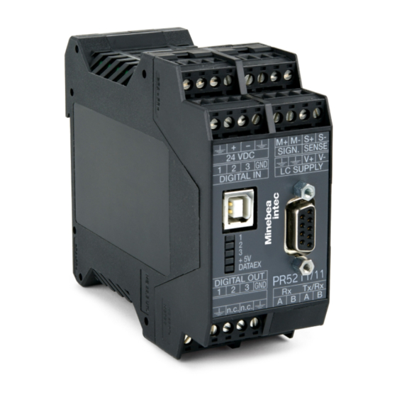
Transmitter Series PR 5211 3 Device description Housing 3.3.1 Sticker The connection diagram is located on the side of the housing. 3.3.2 Dimensions All dimensions in mm Minebea Intec EN-12... -
Page 15: Display And Operating Elements
3 Device description Transmitter Series PR 5211 Display and operating elements 3.4.1 General information The transmitter of the PR 5211 series can only be operated by Notebook/PC. 3.4.2 LEDs The device has 5 green LEDs for the following status displays: Operational status... -
Page 16: Configureit
3 Device description Note: For weight error status, see Chapter 10.1. 3.4.3 ConfigureIt! The configuration and calibration of the transmitter is done via the "ConfigureIt!" program. Installation, see Chapter Operation, see Chapter to Chapter 5.15 Overview of connections Minebea Intec EN-14... -
Page 17: Device Installation
Secure the cable at the place of installation, e.g. using cable ties. Remove the insulation from the cable ends and keep the strands short. Connect the screens to the screen clamping rail using screen terminals; see Chapter 4.3. Establish grounding/equipotential bonding between devices/system components. EN-15 Minebea Intec... -
Page 18: Emc-Compliant Installation
Connect the mounting rail to protective ground. Keep measurement and data cables away from power cables. Description Screen clamp (e.g. Phoenix SK8-D) Screen clamping rail (e.g. Phoenix NLS-CU 3/10) Rail connector (e.g. Phoenix AB-SK 65D) Mounting rail (35 mm) Minebea Intec EN-16... -
Page 19: Hardware Construction
RS-485 interface The device is equipped with an integrated RS-485 interface. The interface can be configured by software. The RS-485 interface serves for the connection of the remote display and PC for data transfer using the SMA protocol. EN-17 Minebea Intec... - Page 20 Cable length max. 1000 m <…> = preset values (factory settings) The RS-485 receiver (Rx) has an internal terminating resistor of 120 Ω and 1.6 Ω for internal bus power supply (- on RxA + on RxB). Minebea Intec EN-18...
- Page 21 ] - [oP 13] - [SEndModE] - [SEnd] ] - [oP 14] - [WEIght] - [FolloW] ] - [oP 15] - [WPkEy] - [SElEct] The following operations are possible from the connected remote display: Display current weight mode Set tare Reset tare Set zero EN-19 Minebea Intec...
-
Page 22: Usb Interface
[Parameters] - [Communication] - [SMA protocol] 4.4.3 USB interface Configuration and calibration is performed using the "ConfigureIt!" software (version 6.00 or higher) via the USB interface; see Chapter and 5.7. Technical data Description Data Connection USB-B port Connection cable USB 2.0 A>B Minebea Intec EN-20... -
Page 23: Analog Outputs
0…20 mA in max. 40,000 counts @ 0 to …20 mA: <0.05% Output: Linearity error @ 4 to …20 mA: <0.025% Output: <100 ppm/K Temperature error Max. 0… to 500 Ω Output: Load Output: Protected against short- circuit EN-21 Minebea Intec... -
Page 24: Digital Inputs
The voltage level corresponds to the voltage drop at the external 500 Ω resistor. 4.4.5 Digital inputs 3 passive opto-decoupled inputs are permanently built into the device. The interface can be configured by software. All inputs have a common GND (-). Minebea Intec EN-22... -
Page 25: Digital Outputs
If the voltage at terminals (in this example: 1-GND) is 10 V DC, input 1 is active (true). 4.4.6 Digital outputs 3 passive opto-decoupled outputs are permanently built into the device. The interface can be configured by software. All outputs have a common GND (-). EN-23 Minebea Intec... - Page 26 Data Connection Terminal, 4-pin Number of outputs Supply voltage Max. 24 V +10%, external Switching current Max. 30 mA Signals GND (-) common for all outputs Potential isolation Yes, via optocoupler Cable length Max. 50 m screened Minebea Intec EN-24...
-
Page 27: Connection Of Analog Load Cells And Weighing Platforms
Connection of analog load cells and weighing platforms 4.4.7.1 General information Load cells can be connected to the device doing the following: One load cell directly, see Chapter 4.4.7.2 4.4.7.3 several load cells in the junction box via connecting cable, see Chapter 4.4.7.4 3.3.1 EN-25 Minebea Intec... - Page 28 Transmitter Series PR 5211 4 Device installation Note: The colors listed here apply for the Minebea Intec load cell and connection cables of type "PR …" Color code Black Blue Green Gray White For additional information on the connection of load cells and cable junction boxes, refer to the corresponding installation manuals.
- Page 29 - Signal (LC output) SENSE S+ + Sense/wh + Sense SENSE S- - Sense/bk - Sense LC SUPPLY V+ + Supply/rd + Supply (excitation) LC SUPPLY V- - Supply/bu - Supply (excitation) LC SUPPLY ⏚ Grounding Screen (ground) EN-27 Minebea Intec...
- Page 30 The supply voltage is fixed at 12 V DC and protected against short circuits. For further technical data, see Chapter 11.6.1. 4.4.7.5 Connecting load cells of type series PR 6221 See installation manuals of PR 6221 and PR 6021/08, -/68. Minebea Intec EN-28...
- Page 31 Supply voltage 12 V ±0.8 V (symmetrical to housing ground) Sense voltage 12 V ±0.8 V (symmetrical to housing ground) Measuring voltage 0–12 mV @ LC with 1.0 mV/V 0–24 mV @ LC with 2.0 mV/V EN-29 Minebea Intec...
- Page 32 The center of the external supply voltage (0 ext. supply) should be connected to ground to ensure that the voltage reacts symmetrically to 0. External supply specifications: 6 V DC +5%, -30%; ripple max. 50 mVpp; asymmetry max. ±3%. The internal supply is not connected. Minebea Intec EN-30...
- Page 33 The screen of the load cell cable and the screen of the connecting cable must not be connected inside the junction box, if connection of both ends is not permissible according to the regulations for installation in the ex-zone. EN-31 Minebea Intec...
- Page 34 Transmitter Series PR 5211 4 Device installation ① Equipotential bonding conductor ② Mounting rail ③ Screen Minebea Intec EN-32...
- Page 35 The cable screens must be connected to the grounding terminal of the device. If the measuring lines (+M, -M) are screened individually, these screens must be connected to the grounding terminal as well (see also Chapter 4.3). EN-33 Minebea Intec...
- Page 36 Transmitter Series PR 5211 4 Device installation Example: Platform with 4-wire connection The following links between the terminal contacts are provided: ① from SIGN. SENSE S+ to LC SUPPLY V+ ② from SIGN. SENSE S- to LC SUPPLY V- Minebea Intec EN-34...
-
Page 37: Profibus Dp Interface
Communication protocols and syntax comply with the ProfiBus-DP standard to IEC 61158, with transfer rates up to 12 Mbit/s. Connection to the ProfiBus is established using the 9-pin D-Sub female connector on the front of the device. EN-35 Minebea Intec... - Page 38 Cable length The max. distance of 200 m can be extended at 1.5 Mbit/s by means of an additional repeater. Certificates Profibus test center Comdec in Germany and PNO (Profibus User Organization). Industry-compatible CE, UL, and cUL Minebea Intec EN-36...
- Page 39 RS-485 specifi- Data core B/D (P) cation 4 if required "Request To Send" (only when using a repeater) 5 -------------------- DGND Insulated GND to RS-485 side 6 -------------------- Insulated power supply +5 V to RS-485 side Not connected EN-37 Minebea Intec...
- Page 40 4 Device installation Pin assignment Signal Color Description 8 -------------------- RxD/TxD-N (negative) ac- Green Send/receive data cording to RS-485 specifi- Data core A/D (N) cation Not connected Note: Only plug connections with integrated terminating resistors may be used. Minebea Intec EN-38...
-
Page 41: Getting Started
When the CAL switch is in "opened" position, the calibration data and parameters can be changed using the PC program or via the ProfiBus connection. With the CAL switch in the "closed" position, the calibration data (e.g. dead load, SPAN) and parameters (measuring time, zero tracking etc.) cannot be changed. EN-39 Minebea Intec... -
Page 42: Switching On The Device
Switching on the device The device can be set up as follows: Via a notebook/PC with the supplied program "ConfigureIt! 6.00" (or higher). The ProfiBus interface allows access to individual parameters. The weight display is shown. Minebea Intec EN-40... -
Page 43: Switching Off The Device
Open the internet browser. Note: Please note, the internet address may have changed. In that case please contact Minebea Intec. 2. Type the URL [www.ftdichip.com/Drivers/VCP.htm] and confirm. The web page is displayed. 3. Click on the link of the appropriate operating system in the table (e.g. [2.08.28]). -
Page 44: Load And Save The Settings And Configuration
Data in PR 5211 The current dataset can be loaded from the PR 5211 to "ConfigureIt!", it can be edited and again saved in the PR 5211. The datasets can be loaded and saved in the menu [ADU] and [Parameter]. Minebea Intec EN-42... -
Page 45: Archive Data In The Pc
The default values (factory settings) will be loaded in the DEFAULT.DAT file for "ConfigureIt!". Note: The default dataset cannot be overwritten. To store a new configuration, the name must be changed. Save dataset 2. Save the modified dataset under a name other than DEFAULT.DAT. EN-43 Minebea Intec... -
Page 46: Print Dataset
Select language If the program was set to German [D]: If the program was set to English [GB] (automatically set at the first start of the program): Select [File] - [Select Language]. A selection window opens. Minebea Intec EN-44... -
Page 47: Status Line
The program has established a communication connection using the PC inter- face COM4 with a PR 5211 of version (release) 06.00. A dataset for the device type PR 5211/00 is loaded. The device has the board number 4294967295. The current weight is +2426 kg. EN-45 Minebea Intec... -
Page 48: Adu
During calibration the display resolution can be increased by factor 10. [Span] During calibration it has to be decided: To set SPAN by weight (load the scale with the calibration weight and enter the value of the calibration weight) Minebea Intec EN-46... - Page 49 Load cell supply voltage 12 V DC [Overload] Enter in d, maximum permitted range 0 d to 9999999 d, default = 9 d. In case of weight value over FSD + overload, an error message will be generated. The overload range EN-47 Minebea Intec...
- Page 50 (relative) in relation to the full scale. Example: FSD = 3000, result: Should be 3000 for absolute, should be 0 for relative. The calibration (with/without weights) is completed with a test measurement. The result is scaled. The full scale is displayed. Minebea Intec EN-48...
- Page 51 Enter multiples of the measurement time. The permitted range: is: 0 … 100, default: 0 (automatic Zerotrack = off) Automatic Zerotrack can be switched off by setting Zerotrack repeat = 0. EN-49 Minebea Intec...
-
Page 52: Parameter
Gross weight value is linked to the analog output. Net weight value is linked to the analog output (if not tared: gross weight). [Analog range] The following can be set: 0 … 120 mA Analog output range 4 … 120 mA Analog output range Minebea Intec EN-50... - Page 53 The address on the ProfiBus has to be defined here, valid addresses are in the range 1, 2 … 126, Default: 10. [Bus size] The normal bus size is 8 bytes. 10 byte bus size is required for a coded data transfer. Default: 8. EN-51 Minebea Intec...
- Page 54 Each limit has two weight values: the values for limit on and limit off. These two values are compared with the actual weight. If they are same, an output signal is generated, which can be linked to one of the 3 outputs. Minebea Intec EN-52...
- Page 55 1 (Limit 1 out) ON if the weight (Wgt) exceeds the value. switches output 2 (Limit 2 out) OFF if the weight falls below the value. The default values for the limits (Limit 1 … Limit 3) are 0 kg. EN-53 Minebea Intec...
-
Page 56: Calibration
Transmitter Series PR 5211 5 Getting started 5.13 Calibration In this menu item, the calibration of the weighing point is performed. With [Start Calibration] a new calibration will be done. With [Modify Calibration] an existing calibration can be changed. Minebea Intec EN-54... -
Page 57: Smart Calibration
Before starting the calibration the load cell data have to be entered and saved to the PR 5211. Prerequisite: The software ConfigureIt! 6.00 is installed; see the header of the following figure. The instrument software 6.00 is installed; see the status bar of the following figure. EN-55 Minebea Intec... - Page 58 [Hysteresis correction] Only if [with] has been selected, the values for [Correction A/B] must be entered. For this data refer to the load cell certificate. 3. Press [Download to PR5211/00] to save the data in PR 5211. Minebea Intec EN-56...
- Page 59 5 Getting started Transmitter Series PR 5211 4. Select [Calibration]. The sequence has to be performed as described in Chapter 5.13, only in Step 4 [by load cell data] has to be selected. EN-57 Minebea Intec...
-
Page 60: Analog Output Current Adaption
With [Reset Adaption] the values are reset to [4,000] and [20,000]. 5.15 Status In this menu, the current status of the weight and the digital inputs and outputs is displayed. The scale can be tared, set to zero and switched to the test mode. Minebea Intec EN-58... - Page 61 Zero offset from the calibrated zero point (dead load). By pressing the Set zero key, the new zero point will differ from the calibrated zero point. to switch on and switch off the test mode. to tare the scale and reset tare. to set the scale to zero. EN-59 Minebea Intec...
-
Page 62: Sma Protocol
The following commands are supported: W, Z, D, A, B, <ESC>, H, P, Q, R, S, T, M, C, I, N Minebea Intec EN-60... -
Page 63: Profibus Interface
Control bits (control bits) MISO Read data Read_Value_Selected Status bits Status bits (status bits) (status bits) Write window (MOSI) Byte Field Description Write data (MSB) Contains the data to be written, e.g., analog output. Write data Write data EN-61 Minebea Intec... - Page 64 Read data (MSB) Contains the data to be written, e.g. gross value. Read data Read data Read data (LSB) Read_Value_Selected Read_Value_Select (function) from the write window is mirro- red if the data in "Read data" is available. Minebea Intec EN-62...
- Page 65 The weight value is within center zero (0 ±0.25 d). BelowZero 1 bit The weight value is negative (gross < 0 d). Overload 1 bit The weight value has exceeded the measuring range. No valid weight data is specified (gross > FSD+over- load). EN-63 Minebea Intec...
-
Page 66: Reading And Writing Data With Function Numbers
3. Write the function number as Write_Value_Select in byte 5 of the write window (e.g., "Basic” application: 190 = analog output 1). 4. Wait until Write_Active = 1 in the read window. 5. Write 0 in byte 5 (Write_Value_Select). Write_Active is reset. Minebea Intec EN-64... -
Page 67: Reading And Writing Bits Directly
The direct control bits are also available continuously. 7.2.3.1 Reading status bit The status bits in bytes 5-7 of the read window are always available and can be read directly by the master. EN-65 Minebea Intec... -
Page 68: Waiting For The Result Of The Action
7.2.5.5 Function number 5: device type and software version (read), see Chapter 7.2.5.6 Function number 6: serial number of the weighing point (read), see Chapter 7.2.5.7 Function numbers 8 to 15: weight data (read), see Chapter 7.2.5.9 Minebea Intec EN-66... - Page 69 The gross weight value is within the zero setting range. Standstill The scale is stable. OutOfRange Below zero or above max. (FSD). The measuring signal is negative (inverse conversion); error 7 Sense voltage not present or too low; error 6 EN-67 Minebea Intec...
- Page 70 One byte for the weight unit; content in decimal form: 0 to 255 1 = mg (milligrams) 2 = g (grams) 3 = kg (kilograms) 4 = t (tons) 5 = lb (pounds) 6 = l (liter) Minebea Intec EN-68...
- Page 71 102, 103 = EAROM error (command SaveProcess, function number 2) 104 = wrong access code 106 = baudrate of remote display cannot be altered 107 = no standstill with GetFixTare. 108 = parameter not valid (at entering via PLC) EN-69 Minebea Intec...
- Page 72 Function number 20 and 21: Parameter channel (Read/Write) Function number 20 Parameter value Function number 21 Parameter index 7.2.5.11 Function number 22…27: Limit value (Read/Write) Function number 22 Limit 1 on Function number 23 Limit 1 off Minebea Intec EN-70...
- Page 73 Function number 89 ResetError The CmdError error bit is reset. Function number 90 SaveProcess The process data are saved in EAROM. Limits (function number 22…27) Fixed analogue output value (function number 30) Preset tare (function number 31) EN-71 Minebea Intec...
- Page 74 Function number 121 ResetError Function number 122 SaveProcess Function number 123 SetParam Function number 124 GetParam Function number 125 SaveConfig Note: To prevent frequent writing to the EAROM, the write interval should be no shorter than 15 seconds. Minebea Intec EN-72...
-
Page 75: Example: Reading The Gross Weight
The rest of the parameters belong to the advanced configuration, which can be found on separate pages. Values marked as (factory settings) are data in the original condition as delivered from the factory. One parameter always uses 4 bytes (DINT format) EN-73 Minebea Intec... -
Page 76: Configuration Parameters
Parameter 2: Scaling weight value for 0/4 mA output Bit 7 Bit 6 Bit 5 Bit 4 Bit 3 Bit 2 Bit 1 Bit 0 Byte 0 WEIGHT MSB Byte 1 WEIGHT MSB Byte 2 WEIGHT MSB Byte 3 WEIGHT LSB Minebea Intec EN-74... - Page 77 Bit 2 Bit 1 Bit 0 Byte 0 Byte 1 Output 1, default = 0 Byte 2 Output 2, default = 0 Byte 3 Output 3, default = 0 Description Value Transparent* Aduerr Limit1** Limit2** Limit3** Tare active EN-75 Minebea Intec...
-
Page 78: Calibration
Accessing parameter 21…53 will give an error message, if CalActiv has not been set. P21 - P24 and P27 can only be written. While reading, the error code 108 is generated. The calibration data (parameter 21…27) are written in a fixed sequence. Minebea Intec EN-76... - Page 79 Parameter 23 = 1 ⇔ the current weight will be transferred as the dead load. Load the scale with a known calibration weight (e.g. 250.0 kg) Parameter 24 = 2500 ⇔ 250.0 kg Parameter 20 = 3 save and exit Calibration. After each step, always check for errors. EN-77 Minebea Intec...
-
Page 80: Parameter 20: Calibration Start/Stop (Write)
Parameter 20 = 3 Parameter 20 = 4 SaveAndExit UndoAndQuit Function StartCal Test the CAL switch, set CalActiv. Factory settings The calibration data and parameters are reset to the original condition as deli- vered from the factory (see Chapter 5.1.3.3). Minebea Intec EN-78... -
Page 81: Adu Parameters
Parameter P22: Scale interval (Step width, Write) Bit 7 Bit 6 Bit 5 Bit 4 Bit 3 Bit 2 Bit 1 Bit 0 Byte 0 Byte 1 Byte 2 Byte 3 Scale interval Scale interval: 1, 2, 5, 10, 20, 50 EN-79 Minebea Intec... -
Page 82: Parameter P23: Setdeadload With Weight (Write Only)
Bit 6 Bit 5 Bit 4 Bit 3 Bit 2 Bit 1 Bit 0 Byte 0 SPAN MSB Byte 1 SPAN MSB Byte 2 SPAN MSB Byte 3 SPAN LSB SPAN in mV/V (value in mV/V) x 10 Minebea Intec EN-80... -
Page 83: Parameter P27: Calctest (Write)
TIME LSB TIME: Measurement time msec 10 … 1920, default = 320 msec Applicable only if the digital filter has been set to [off]. The parameter P53 will be set accordingly. 10…160 ms –> P53: 4 … 0 EN-81 Minebea Intec... -
Page 84: Parameter P43: Test Operating Mode
Bit 2 Bit 1 Bit 0 Byte 0 Byte 1 Byte 2 Byte 3 TIME Number of measurement times, during which the standstill condition should be reached. TIME: 0 … 100 M (measurement times), default = 8 Minebea Intec EN-82... -
Page 85: Parameter P47: Zero Range
Bit 7 Bit 6 Bit 5 Bit 4 Bit 3 Bit 2 Bit 1 Bit 0 Byte 0 Byte 1 Byte 2 Byte 3 REPEAT REPEAT: 0 … 100 measurement times, default = 0 (Zerotrack is off) EN-83 Minebea Intec... -
Page 86: Parameter P51: Overload
P99. The parameter P99 can always be written. To activate protection, P99 must be set again to –1. If the CODE is set to 0, no access control checks will be performed. Minebea Intec EN-84... -
Page 87: Maintenance/Repairs/Soldering Work/Cleaning
Repairs Repairs are subject to inspection and must be carried out at Minebea Intec. In case of defect or malfunction, please contact your local Minebea Intec dealer or service center for repair. When returning the device for repair, please include a precise and complete description of the problem. -
Page 88: Disposal
We reserve the right not to accept products that are contaminated with hazardous substances (ABC contamination) for repair. Should you have any further questions, please contact your local service representative or our service center. Minebea Intec GmbH Repair center Meiendorfer Strasse 205 A 22145 Hamburg, Germany Phone: +49.40.67960.666... -
Page 89: Error Messages
Altern. flash. 1Hz Flash. 1Hz Flash. 1Hz Altern. flash. 1Hz Flash. 1Hz Flash. 1Hz Flash. 1Hz Flash. 1Hz Altern. flash. 1Hz Note: In all other messages, the top status LED will flash. FSD = Full scale deflection EN-87 Minebea Intec... -
Page 90: Technical Data
Current number 30 = Hamburg 252* = April 2010 * Is increment according to the year group table of Minebea Intec. 11.4 General data The following characteristics are valid after a warm-up time of at least 30 minutes (reference temperature: 23 °C). -
Page 91: Electromagnetic Compatibility (Emc)
Load cell supply U = ±6 VDC for I = 160 mA, protected by Multifuses. for max. 8 load cells, each with 650 Ω Supply voltage 12 V DC for max. 4 load cells, each with 350 Ω EN-89 Minebea Intec... -
Page 92: Principle
PROFIBUS DIN 19245: PROFIBUS, Process field bus (part 1 and 3) Baud rates 9.6; 19.2; 93.75; 187.5; 500 [kBps], 1.5; 3.0; 6.0; 12.0 [MBps], automatic detection Buffer size 8 bytes I/O data 8 bytes UserPrm Sync Freeze Minebea Intec EN-90... -
Page 93: Mechanics
116 mm 11.8.3 Weights Net weight 0.30 kg Shipping weight 0.45 kg 11.9 Documentation on the CD included The documents and manuals listed in the appendix (see Chapter 12.2) can be found on the PR 5211 CD. EN-91 Minebea Intec... -
Page 94: Appendix
12.2 Certificates Ser. no. Description Document no. EU-Declaration of Conformity MEU17026 Declaration of Conformity MDC17004 Certificate of Conformity TR CU 020 RU Д-DE.A303.B.06727 The documents listed in the table can be found on the PR 5211 CD. Minebea Intec EN-92... - Page 96 Published by Minebea Intec GmbH | Meiendorfer Strasse 205 A | 22145 Hamburg, Germany Phone: +49.40.67960.303 | Email: info@minebea-intec.com www.minebea-intec.com...
Need help?
Do you have a question about the PR 5211 Series and is the answer not in the manual?
Questions and answers