Table of Contents

Related Manuals for Minebea Intec MP 26


Summary of Contents for Minebea Intec MP 26
- Page 1 Installation and Calibration Manual Transmitter MP 26 Installation and 9499 050 26000 Edition 5 07/10/2018 Calibration Manual for Rel. 1.1 Minebea Intec GmbH, Meiendorfer Str. 205 A, 22145 Hamburg, Germany Phone: +49.40.67960.303 Fax: +49.40.67960.383...
- Page 2 Any information in this document is subject to change without notice and does not represent a commitment on the part of Minebea Intec unless legally prescribed. This product should be operated only by trained and qualified personnel. In correspondence concerning this product the type, name and release number as well as all license numbers in relation to the product have to be quoted.
-
Page 3: Table Of Contents
MP 26 Transmitter Installation and Calibration Manual Table of Contents TABLE OF CONTENTS ............................. 1 MP 26 TRANSMITTER ..........................3 1.1............................3 ESCRIPTION 1.1.1. Versions ............................3 1.1.2. Transmitter Overview / Features ....................3 1.2............................... 4 OUSING 1.3. - Page 4 MP 26 Transmitter Installation and Calibration Manual POSSIBLE ERRORS & REMEDIES ..................... 42 6.1............................. 42 ENERAL 6.2............................43 RROR 6.3............... 44 ETECTION AND ISPLAY OF ENSOR AND IRING ERRORS TECHNICAL DATA ..........................45 7.1..............................45 NPUTS 7.1.1.
-
Page 5: Mp 26 Transmitter
MP 26 Transmitter Installation and Calibration Manual 1. MP 26 Transmitter 1.1. Description The instrument is equipped with a monochrome, two-line 4-character display and a keypad which contains 3 keys. The instrument is a weighing system, especially designed for tank &... -
Page 6: Housing
MP 26 Transmitter Installation and Calibration Manual 1.2. Housing The entire housing is IP20 Protected. The overall dimensions of the device are 117.5 x 22.5 x 99 mm (L x W x H). The unit is designed for vertical mounting on 35 mm top-hat rails to EN 50022. - Page 7 Note: The transmitter MP 26 does not contain any maintenance parts, i.e. the unit need not be opened by the customer. The unit may be operated only in environments for which it is suitable due to its protection type. The housing ventilation slots must not be covered.
-
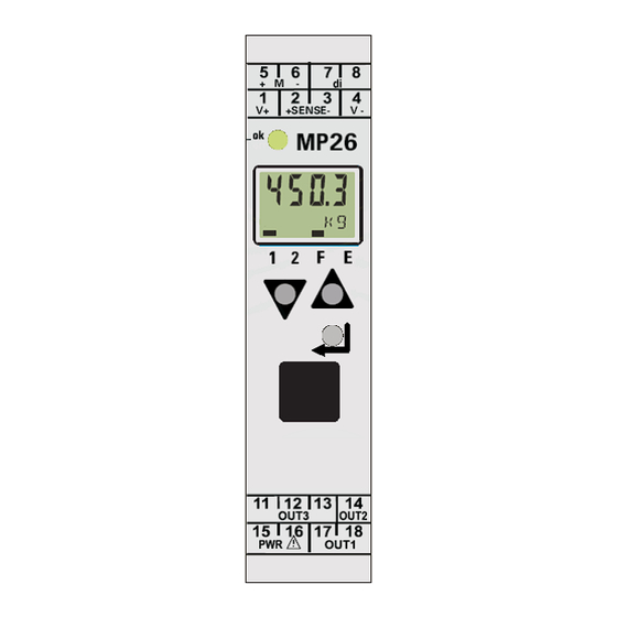
Page 8: Displays And Controls
MP 26 Transmitter Installation and Calibration Manual 1.3. Displays and Controls Display Line 1: Displays process value Display Line 2: Displays unit / extended operating level / error list / Conf and PArA level values Status Indicator: The statuses of the active functions are displayed as bars above the corresponding functionality. - Page 9 MP 26 Transmitter Installation and Calibration Manual Increment Key: Is used to increment the values / slave pointer/ to display maximum value. Enter Key: Is used to select extended operating level or error list, parameter, configurations and installations levels. LEDs: This LED indicates the status of the device. There are 3 color codings: •...
-
Page 10: Installation
MP 26 Transmitter Installation and Calibration Manual 2. Installation 2.1. Connecting the Supply Voltage Depending on the device version, connect the supply voltage as below: MP 26/00 90…260 V AC ports: 15, 16 MP 26/01 24 V AC / DC ports: 15, 16 2.2. -
Page 11: Connecting Outputs Out1 / Out2
MP 26 Transmitter Installation and Calibration Manual 2.4. Connecting Outputs OUT1 / OUT2 Two digital outputs can be set from the device. The outputs are activated according to the configuration and parameter settings. The relay outputs should be max. 250V/2A. -
Page 12: Connecting Output Out3
MP 26 Transmitter Installation and Calibration Manual 2.5. Connecting Output OUT3 The Out3 is an analog output through which voltage or current can be led based on the configuration. Current (0...20mA) ports: 11, 12 Voltage (0...10V) ports: 12, 13 Its current output is configurable 0/4...20 mA, short-circuit proof. -
Page 13: Operation Via Front Keys
MP 26 Transmitter Installation and Calibration Manual 3. Operation via Front Keys 3.1. Power ON Switching ON the supply powers up the device, the device initializes itself (display, load cell lines) and checks for any errors. The device status is indicated by the LED (red / green). For proper operation, the system should be warmed up for minimum 20 minutes. -
Page 14: Key Pad
MP 26 Transmitter Installation and Calibration Manual 3.4. Key Pad There are 3 keys on the device: Enter key Increment key Decrement key 3.4.1. Enter Key Functionality By using the enter key, different values can be loaded in display line 2. -
Page 15: Increment & Decrement Key Functionality
MP 26 Transmitter Installation and Calibration Manual 3.4.2. Increment & Decrement Key Functionality Moving to Menu Levels The increment / decrement keys can be used to move through different submenu levels. The increment key performs forward movement and the decrement key performs backward movement. -
Page 16: Configuration Levels
MP 26 Transmitter Installation and Calibration Manual 3.5. Configuration Levels There are 3 configuration levels/modes available for the MP 26: 1. Normal Mode: displays the weight value along with its unit 2. Installation Mode: enables user to calibrate the system 3. -
Page 17: Parameter And Configuration
MP 26 Transmitter Installation and Calibration Manual 3.7. Parameter and Configuration 3.7.1. Device Parameter Parameter enables us to set to the input and limit values. The parameter for input and limit values are given below. Depending on the device version and set configurations, values may be hidden. -
Page 18: Zero Setting
MP 26 Transmitter Installation and Calibration Manual Configuration Depending on the device version and other configurations, the configuration data may be hidden. The data that can be operated via the front panel are shown below: 3.7.2. Zero Setting Zero setting is used to zero the scale. It deletes the display of accumulated deposits that could falsify the measurement. -
Page 19: Tare Setting
MP 26 Transmitter Installation and Calibration Manual 3.7.3. Tare Setting The tare function is used to tare the weight of the scale and the scale displays zero. Then, the net weight can be measured (net = gross – tare). The gross weight can be found by switching off the tare function. -
Page 20: Limit Value Processing
3.8. Reset to Factory Settings In the event of faulty configuration, the MP26 transmitter can be reset to the default manufacturer’s state. The steps for resetting MP 26 are as given below: 1. Keep the increment and decrement keys pressed during power-on. After the display shows, wait for 1 sec until the display shows. -
Page 21: Calibration
MP 26 Transmitter Installation and Calibration Manual 4. Calibration 4.1. General Calibration of the scale must be followed by initial setting. After that the instrument can be calibrated for the given weight or value. The key calibration terms are as follows. -
Page 22: Calibration
MP 26 Transmitter Installation and Calibration Manual Overload The device is able to generate an alarm signal on overload. For this signal to assert the limits, the values should be entered suitably in terms of their physical weight values. Generally, this is set as:... -
Page 23: Calibration Via The Device
MP 26 Transmitter Installation and Calibration Manual 4.3. Calibration via the Device Calibration via the device is possible by pressing a combination of keys. The calibration procedure is done by making the initial settings, then calibrating the device by load or value. -
Page 24: Initial Setting Via The Device
MP 26 Transmitter Installation and Calibration Manual 4.3.1. Initial Setting via the Device Disable Tare & Special Linearization Step Display Line 2 Operation Description Press for more than 3 sec If the initial settings are made to display InSt. earlier, then calibration mode is activated directly. - Page 25 MP 26 Transmitter Installation and Calibration Manual Step Display Line 2 Operation Description Now, the display alternates Disable the special linearization. between S.Lin and value. Use and set the value to zero. Press twice to move to Lim. Use the...
- Page 26 MP 26 Transmitter Installation and Calibration Manual Initialize Inputs & Outputs In the process of setting the values below, the display alternates between the corresponding menu level and value. Set the value using , then press . After you press , the value is set in the corresponding menu level and the display moves to the next menu level.
- Page 27 MP 26 Transmitter Installation and Calibration Manual Step Display Line 2 Operation Description Set the analog output value Enter the weight value for which using , then press 100% analog output has to be to set the value and move to generated.
-
Page 28: Calibration By Load
MP 26 Transmitter Installation and Calibration Manual 4.3.2. Calibration by Load Calibration by load can be done directly in calibration mode if the initial settings were previously configured. Alternatively, configure the initial settings as explained above and then go to calibration mode. - Page 29 MP 26 Transmitter Installation and Calibration Manual Step Display Line 2 Operation Description In this menu level, the display Load the system with the toggles between InH.1 and standard weight OFF. Now calibrate the system for standard weight. to enable the XXXX value This only shows the measured value.
-
Page 30: Dead Load Correction
MP 26 Transmitter Installation and Calibration Manual 4.3.3. Dead Load Correction The dead load can be adjusted without the need of an entire calibration. The steps are explained as follows. Step Display Line 2 Operation Description Press more than 3 sec it If the initial settings have been will display InSt. - Page 31 MP 26 Transmitter Installation and Calibration Manual Step Display Line 2 Operation Description Adjusting the Dead Load Calibration Press for more than 3 sec After finishing the full-scale to display InSt. Press calibration, the dead weight is go to SEt. Use shown in display1.
-
Page 32: Calibration By Value
MP 26 Transmitter Installation and Calibration Manual 4.3.4. Calibration by Value Calibration by value can be done in an indirect way. Switch to SCAL mode if the initial settings have been configured previously or configure the initial settings as explained above and then switch to SCAL mode. - Page 33 MP 26 Transmitter Installation and Calibration Manual Step Display Line 2 Operation Description OuL.1 and set zero. In this menu level, the display Then press alternates between OuL.1 and zero. Setting 0% corresponds to zero weight. InH.1 Setting the calibration In this menu level, the display weight.
-
Page 34: Zero Setting
MP 26 Transmitter Installation and Calibration Manual Step Display Line 2 Operation Description InL.1 Set the set dead load in In this menu level, the display percent using . Then alternates between InL.1 and press zero. The dead load in percent is given by Pdead [%] = (dead load * 100)/ max. - Page 35 MP 26 Transmitter Installation and Calibration Manual 4.4. Zero Setting The zero setting is used to zero the scale. It voids the residual weight on the scale which cannot/may not be removed immediately. The procedure for setting zero is: 1. Press for more than 3 sec, it leads to Inst 2.
-
Page 36: Tare Setting
MP 26 Transmitter Installation and Calibration Manual 4.5. Tare Setting The tare function is used to tare the weight on the scale. The scale displays zero. Then, the net weight can be measured (net = gross – tare). The gross weight can be found by switching off the tare function. -
Page 37: Example: Calibration By Value
MP 26 Transmitter Installation and Calibration Manual 4.6. Example: Calibration by Value For example, consider a load cell with 150 kg capacity and a sensitivity of 2mV/V. The voltage between V+ and V- is 10 V. We want to calibrate the system for the 75-kg full-scale capacity plus an unknown dead load. -
Page 38: Setting The Low Pass Filter And Bandwidth
MP 26 Transmitter Installation and Calibration Manual 4.7. Setting the Low Pass Filter and Bandwidth Filter Time A first order mathematical low pass filter with adjustable time constant and bandwidth is built-in. The time constant of the filter must be greater than zero. Normally higher values result in good suppression of disturbances, but in an increased delay of the input signals, i.e. -
Page 39: Configuring Outputs
MP 26 Transmitter Installation and Calibration Manual 5. Configuring Outputs 5.1. Overview Limit values can be configured to generate outputs at Out.1, Out.2, Out.3 ports. Several signals allocated to output are linked by OR logic. The device can generate the output based on ... -
Page 40: Define The Limits
MP 26 Transmitter Installation and Calibration Manual 5.2.1. Define the Limits The first step in limit value processing is to set or unset the source of limits. This can be set in the configuration menu. 1. Press for more than 3 sec. It leads to Inst. -
Page 41: Configure The Output
MP 26 Transmitter Installation and Calibration Manual 5.2.2. Configure the Output 6. Use to move to the required Out.x and press key. 7. Set the parameters below using , then press key to confirm and move to the next menu/sub menu. -
Page 42: Operating Principle: Limit Value Processing
MP 26 Transmitter Installation and Calibration Manual 5.2.4. Operating Principle: Limit Value Processing Note: The limit values have to be entered in units of weight. If confout.nO.Act1.(inverse), output will be generated which is inverted to the figure shown above. With measurement value or signal change with latch selected ( ConF / Lim / Fnc.x = 2, 4), the alarm relay remains set until it is reset in the error list. -
Page 43: Output Out.3 (Analog)
MP 26 Transmitter Installation and Calibration Manual 5.3. Output Out.3 (Analog) The device can be configured to take the output measure as constant voltage or current. The procedure for configuring Out.3 is: 1. Press the more than 3 sec. It will leads to Inst 2. -
Page 44: Possible Errors & Remedies
MP 26 Transmitter Installation and Calibration Manual 6. Possible Errors & Remedies 6.1. General In this chapter, the possible errors and their remedies are discussed. An error in the device is identified by a marker over the E in display line 2 as shown in the figure. -
Page 45: Error List
MP 26 Transmitter Installation and Calibration Manual 6.2. Error List Error Description Cause Possible Remedy Internal error, cannot be E.g. defective Contact Service. corrected EEPROM Return device to manufacturer Internal error, resettable E.g. EMC trouble Keep measuring and supply cables separate. -
Page 46: Detection And Display Of Sensor And Wiring Errors
MP 26 Transmitter Installation and Calibration Manual 6.3. Detection and Display of Sensor and Wiring errors 1) Break in the supply measuring or sense lines: "FAIL" is displayed on the process value display and “FbF.1" in the error list. (A substitute value (In.F ) can be entered in the event of a sensor error.) 2) Wrong polarity of supply, sense and input signal lines: "FAIL"... -
Page 47: Technical Data
MP 26 Transmitter Installation and Calibration Manual 7. Technical Data 7.1. Inputs 7.1.1. Input M Resolution: >19 Bit Decimal point: 0 to 3 decimals Digital input filter: adjustable 0.0 to 999.9 s Scanning cycle: 50 ms Linearization: 31 Segments, adaptable with Engineering... -
Page 48: Outputs
MP 26 Transmitter Installation and Calibration Manual 7.2. Outputs 7.2.1. Relay Outputs OUT1, OUT2 Contact type: 2 normally open with common contact connection Max. contact rating: 500 VA, max. 250 V, max. 2 A at 48...62 Hz, ohmic load Min. contact rating:... -
Page 49: Galvanic Isolation
MP 26 Transmitter Installation and Calibration Manual 7.3. Galvanic Isolation Galvanic isolation between inputs and outputs as well as from the supply voltage is provided. Test voltages Between power supply and inputs/outputs: 2.3 kV AC, 1 min Between inputs and outputs: 500 V AC;... -
Page 50: Engineering Front Interface
Installation and Calibration Manual 7.5. Engineering Front Interface Connection to the controller front via a PC adapter (see ‘Additional Accessories’). The Engineering software enables the MP 26 to be configured, parameters set, and operated. 7.6. Environmental Conditions 7.6.1. Protection mode... -
Page 51: General
MP 26 Transmitter Installation and Calibration Manual 7.7. General 7.7.1. Housing front Material: Polyamide PA 6.6 Flammability class: VO (UL 94) 7.7.2. Connecting terminals Material: Polyamide PA Flammability class: V2 (UL 94) for screw terminals 7.7.3. Electrical safety Complies with EN 61 010-1... - Page 52 Published by Minebea Intec GmbH | Meiendorfer Strasse 205 A | 22145 Hamburg, Germany Phone: +49.40.67960.303 | Email: info@minebea-intec.com www.minebea-intec.com...
Need help?
Do you have a question about the MP 26 and is the answer not in the manual?
Questions and answers