Table of Contents

Related Manuals for Minebea Intec MP 26/10


Summary of Contents for Minebea Intec MP 26/10
- Page 1 Installation and Calibration Manual MP 26/10 Installation and 9499 050 26100 Edition 5 07/10/2018 Calibration Manual for Rel. 1.0.102.1 Minebea Intec GmbH, Meiendorfer Str. 205 A, 22145 Hamburg, Germany Phone: +49.40.67960.303 Fax: +49.40.67960.383...
- Page 2 Any information in this document is subject to change without notice and does not represent a commitment on the part of Minebea Intec unless legally prescribed. This product should be operated only by trained and qualified personnel. In correspondence concerning this product the type, name and release number as well as all license numbers in relation to the product have to be quoted.
-
Page 3: Table Of Contents
MP 26/10 Installation and Calibration Manual Table of contents TABLE OF CONTENTS ........................... 1 MP 26 TRANSMITTER ........................... 2 1.1............................2 ESCRIPTION 1.1.1. Versions ............................2 1.1.2. Transmitter Overview / Features ....................2 1.2............................. 3 OUSING 1.3........................5 ISPLAYS AND CONTROLS INSTALLATION ............................ -
Page 4: Mp 26 Transmitter
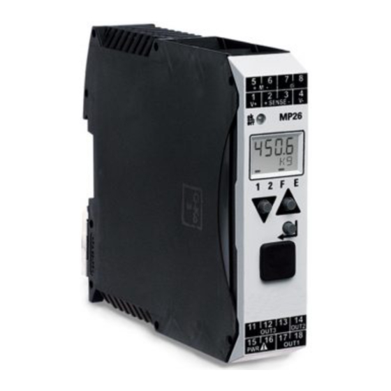
MP 26/10 Installation and Calibration Manual 1. MP 26 Transmitter 1.1. Description The instrument is equipped with a monochrome, two-line 4-character display and a keypad which contains 3 keys. The instrument is a weighing system, especially designed for tank &... -
Page 5: Housing
MP 26/10 Installation and Calibration Manual 1.2. Housing The entire housing is IP20 Protected. The overall dimensions of the device are 117.5 x 22.5 x 99 mm (L x W x H). The unit is designed for vertical mounting on 35 mm top-hat rails to EN 50022. - Page 6 MP 26/10 Installation and Calibration Manual Mounting & Unmounting the device The instruments can be mounted directly side by side. For mounting and dismounting, a minimum of 8 cm free space above and below the units should be provided. Dismounting For mounting, simply clip the unit onto the top-hat rail from the top and click it into position.
-
Page 7: Displays And Controls
MP 26/10 Installation and Calibration Manual 1.3. Displays and controls Display Line 1: Displays process value Display Line 2: Displays unit / extended operating level / error list / Conf and PArA level values Status Indicator: The statuses of the active functions are displayed as bars above the corresponding functionality. - Page 8 MP 26/10 Installation and Calibration Manual Increment Key: Is used to increment the values / slave pointer/ to display maximum value. Enter Key: Is used to select extended operating level or error list, parameter, configurations and installations levels. LEDs: This LED indicates the status of the device. There are 3 color codings: •...
-
Page 9: Installation
MP 26/10 Installation and Calibration Manual 2. Installation 2.1. Connecting the Supply Voltage Depending on the device version, connect the supply voltage as below: MP 26/00 90…260 V AC ports: 15, 16 MP 26/01 24 V AC / DC ports: 15, 16 2.2. -
Page 10: Connecting Outputs Out1 / Out2
MP 26/10 Installation and Calibration Manual 2.4. Connecting outputs OUT1 / OUT2 Two digital outputs can be set from the device. The outputs are activated according to the configuration and parameter settings. The relay outputs should be max. 250V/2A. No contact should exist between common terminals. -
Page 11: Connecting Output Out3
< +0.09% using the current output simultaneously 2.6. MP 26/10 software 2.6.1. Installation The software tool for MP 26 transmitter is contained in the CD-ROM; it can run under Windows 98, -NT, – 2000 or – XP. The steps for installing the software are given below. -
Page 12: Operation
MP 26/10 Installation and Calibration Manual 3. Operation 3.1. Power ON After Switching ON the supply the device gets powered up, the device initializes itself (display, load cell lines) & check for any errors. The status of the device is given by the LED (Red / Green). -
Page 13: Key Pad
MP 26/10 Installation and Calibration Manual 3.4. Key Pad There are 3 keys in the Device. They are Enter key Increment key Decrement key Note: If none of the keys are pressed in operating mode then the system returns to the default display mode 3.5. - Page 14 MP 26/10 Installation and Calibration Manual Create a new project: Enable us to create a new project. A window for selecting the device appears. Select the power supply specific to the device and press the OK button. After pressing OK, the window shown below will open.
-
Page 15: Establishing Connection With Device
MP 26/10 Installation and Calibration Manual 3.5.2. Establishing Connection with Device It is necessary to connect with device for loading/saving/monitoring the device. To do so go to Deviceconnection to device menu. It will display a screen as show below. Select the appropriate COM port in Pc Connector for communication to begin. The rest of the parameters are default and cannot be edited. -
Page 16: Parameter And Configuration
MP 26/10 Installation and Calibration Manual 3.5.3. Parameter and Configuration Parameter The input and limit values are set using parameters. The parameters for input and limit values are given below. Depending on the version of the device and the adjusted configurations, values may be hidden. -
Page 17: Load And Store Setup And Configuration
MP 26/10 Installation and Calibration Manual 3.5.4. Load and Store Setup and Configuration Load Data to / from MP26 Device The current data available on the device can be loaded on to the pc software tool. To do this, go to DeviceLoad dataok. -
Page 18: Print Data Set
MP 26/10 Installation and Calibration Manual 3.5.5. Print Data Set Printer related options are available in the File Menu. The available options are shown in the figure on page 15. Printer setup: Configure the initial settings for the printer in the printer setup menu. -
Page 19: Status
MP 26/10 Installation and Calibration Manual 3.5.7. Status Device communication status The status can be found only in the operation menu and trend menu, because only in these menus exists a continuous data transfer. In other cases, e.g. for loading or storing data, there is only data transfer for a limited time. -
Page 20: Monitoring And Adjusting The Device
MP 26/10 Installation and Calibration Manual 3.5.8. Monitoring and Adjusting the Device This menu will be only visible if the device has established communication with the PC. The options available in this menu level are given below. Overview Display value: displays the weight value. -
Page 21: Calibration
MP 26/10 Installation and Calibration Manual 4. Calibration 4.1. General Information Calibration of the scale must be followed by initial setting. After entering the prerequisites in the initial setting, the instrument can be calibrated for the given weight or value. The key calibration terms are as follows. -
Page 22: Calibration
MP 26/10 Installation and Calibration Manual Overload The device is able to generate an alarm signal on overload. For this signal to assert the limits, the values should be entered suitably in terms of their physical weight values. Generally, this is set as:... -
Page 23: Calibrating Mp26 Via Software
MP 26/10 Installation and Calibration Manual 4.3. Calibrating MP26 via software Calibrating MP26 via Software Calibration through MP26/10 tool is the simplest way. Initial setting of the device follows the calibration. These steps are explained as below. Before configuring the initial settings, load the data from the device. -
Page 24: Calibration By Weight
MP 26/10 Installation and Calibration Manual 4.3.2. Calibration by Weight 1. Load the data from device. 2. Confirm the settings. 3. Go to view parameter as shown in the figure below. Set the dead load/span: The dead load is the constant load which is always present on the weighing scale/system. - Page 25 MP 26/10 Installation and Calibration Manual Calibrate the system for standard Load: 9. Load the system with standard weight. Enter loaded weight in parameterinput 1OuH.1. 10. Next go to the operation window and note the measured value under meas.value correction input.1.
-
Page 26: Calibration By Value
MP 26/10 Installation and Calibration Manual 4.3.3. Calibration by value Calibration by value is done indirectly. It is a theoretical calibration. The calibration is based on the assumption that the dead load is zero and determining the max. calibration. Then, the system shows the dead load. -
Page 27: Example: Calibration By Value
MP 26/10 Installation and Calibration Manual 4.4. Example: Calibration by Value For example, consider a load cell with 150 kg capacity and a sensitivity of 2mV/V. The voltage between V+ and V- is 10 V. We want to calibrate the system for the 75-kg full-scale capacity plus an unknown dead load. -
Page 28: Setting The Low Pass Filter And Bandwidth
MP 26/10 Installation and Calibration Manual 4.5. Setting the Low pass Filter and Bandwidth Filter Time A first order mathematical low pass filter with adjustable time constant and bandwidth is built-in. The time constant of the filter must be greater than zero. Normally higher values result in good suppression of disturbances, but in an increased delay of the input signals, i.e. -
Page 29: Configuring Outputs
MP 26/10 Installation and Calibration Manual 5. Configuring Outputs 5.1. Overview Limit values can be configured to generate outputs at Out.1, Out.2, Out.3 ports. Several signals allocated to output are linked by OR logic. The device can generate the output based on ... - Page 30 MP 26/10 Installation and Calibration Manual Define the Limits The first step in limit value processing is to set or unset the source of limits. This can be set in the configuration menu. 1. Go to parameters and set/unset the required function by using the down arrow button, clicking the value field 2.
- Page 31 MP 26/10 Installation and Calibration Manual Configure the output 3. Go to the required Out.x and set the parameters below. Name Value Description O.Act Direction of operation OUT1 Direct / normally open Inverse / normally closed Lim.1 Signal limit 1(Result of comparison of limit 1 values...
-
Page 32: Operating Principle: Limit Value Processing
MP 26/10 Installation and Calibration Manual 5.2.1. Operating Principle: Limit value processing Note: The limit values have to be entered in units of weight. If confout.nO.Act1.(inverse), output will be generated which is inverted to the figure shown above. With measurement value or signal change with latch selected ( ConF / Lim / Fnc.x = 2, 4), the alarm relay remains set until it is reset in the error list. -
Page 33: Output Out.3 (Analog)
MP 26/10 Installation and Calibration Manual 5.3. Output Out.3 (analog) The device can be configured to take the output measure as constant voltage or current. The procedure for configuring Out.3 is: 1. Go to configurationOut.3 and set/unset the required values using the down arrow... -
Page 34: Analog Output Configuration Example
MP 26/10 Installation and Calibration Manual 5.3.1. Analog output configuration example For example, the device is calibrated for 50% of its measurements in 5000 g, O.typ = 2 (4 to 20 mA), Out.0 = 500, Out.1 = 2500, O.src = 7, O.FAI = 0... -
Page 35: Possible Error & Its Remedies
MP 26/10 Installation and Calibration Manual 6. Possible Error & its Remedies 6.1. General In this chapter the possible errors and its remedies are discussed. The error in the device is identified by a marker over the E in display line 2 as shown in figure. Errors can be viewed by... -
Page 36: Error List
MP 26/10 Installation and Calibration Manual 6.2. Error List Error Description Cause Possible remedy Internal error, cannot be E.g. defective Contact service. corrected. EEPROM. Return device to manufacturer Internal error, resettable. E.g. EMC trouble. Keep measuring and supply cables separate. -
Page 37: Detection & Display Of Sensor Error & Wiring Errors
MP 26/10 Installation and Calibration Manual 6.3. Detection & Display of Sensor error & Wiring errors 1) Break in the supply measuring or sense lines: " FAIL " is displayed on the process value display and “ FbF.1 " in the error list. - Page 38 Published by Minebea Intec GmbH | Meiendorfer Strasse 205 A | 22145 Hamburg, Germany Phone: +49.40.67960.303 | Email: info@minebea-intec.com www.minebea-intec.com...
Need help?
Do you have a question about the MP 26/10 and is the answer not in the manual?
Questions and answers