Table of Contents
Advertisement
Quick Links
Advertisement
Table of Contents

Related Manuals for Minebea Intec PR 5230


Summary of Contents for Minebea Intec PR 5230
- Page 1 Presented By Dallas Ft Worth Austin Houston NicolScales.com 800.225.8181 Contact Us Nicol Scales & Measurement is an ISO Accredited Calibration Company that has provided calibration, repair and sales of all types of weighing and measurement products since 1931.
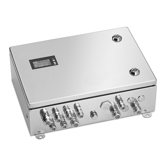
- Page 2 Instrument manual Transmitter in field housing PR 5230 Translation of the original instrument manual 9499 050 52301 Edition 11.0.1 01/09/2017 Release 3.50 Sartorius Mechatronics T&H GmbH, Meiendorfer Str. 205a, 22145 Hamburg, Germany Phone: +49.40.67960.303 Fax: +49.40.67960.383...
- Page 3 Any information in this document is subject to change without notice and does not represent a commitment on the part of Minebea Intec unless legally prescribed. This product should be operated only by trained and qualified personnel. In correspondence concerning this product, the type, designation and version number as well as all license numbers relating to the product have to be cited.
-
Page 4: Table Of Contents
Transmitter in field housing PR 5230 Table of contents Table of contents Introduction............................8 Read the manual.................................8 This is what instructions look like..........................8 This is what lists look like............................8 This is what menus and soft keys look like ......................8 This is what safety instructions look like.........................8 Hotline .................................. - Page 5 4.5.6 Testing the measuring circuit ........................68 4.5.7 External supply of the load cells........................68 4.5.8 Connecting 2…4 load cells via PR 5230/22 load cell junction board ............69 4.5.9 Connecting an analog platform (series CAP…) ...................71 Accessories ................................74 4.6.1 General information ............................74 4.6.2...
- Page 6 Transmitter in field housing PR 5230 Table of contents "Standard" application ........................103 Functions.................................. 103 5.1.1 General information ............................ 103 5.1.2 Display functions............................103 "EasyFill" application ........................104 Functions..................................104 6.1.1 General information ............................104 6.1.2 Display functions............................104 6.1.3 Filling mode ..............................104 Application menu [Start] ............................104...
- Page 7 Transmitter in field housing PR 5230 Table of contents 7.12.4 Setting maximum load..........................129 7.12.5 Determining the scale interval........................129 7.12.6 Determining the dead load ........................130 7.12.7 Calibrating with weight..........................131 7.12.8 Calibrating with mV/V..........................132 7.12.9 Calibrating with load cell data (smart calibration).................. 134 7.12.10 Subsequent dead load correction ......................
- Page 8 Transmitter in field housing PR 5230 Table of contents 7.15.3 Operating parameters..........................186 7.15.4 Print parameters ............................188 7.15.5 Fieldbus parameters............................ 189 7.15.6 Network parameters............................ 193 7.15.7 Configuring display ............................. 194 7.15.8 Configuring limit values..........................195 7.15.9 Configuring digital inputs........................... 201 7.15.10 Configuring digital outputs........................
- Page 9 Transmitter in field housing PR 5230 Table of contents 12.2.2 Read window (output area) ........................257 12.2.3 Reading and writing data .......................... 258 12.2.4 Description of the I/O area (read/write window)..................259 12.2.5 Special hints for DeviceNet and EtherNet-IP ..................264 12.2.6 Fieldbus register ............................
- Page 10 Transmitter in field housing PR 5230 Table of contents 17.3.2 Supply voltage connection 230 V AC....................... 294 17.3.3 Supply voltage connection 24 V AC......................295 17.4 Effect of ambient conditions ..........................295 17.4.1 Ambient conditions .............................295 17.4.2 Electromagnetic Compatibility (EMC).......................295 17.4.3 RF interference suppression ........................296 17.5...
-
Page 11: Introduction
Transmitter in field housing PR 5230 1 Introduction Introduction Read the manual Please read this manual carefully and completely before using the product. This manual is part of the product. Keep it in a safe and easily accessible location. This is what instructions look like 1. -
Page 12: Hotline
1 Introduction Transmitter in field housing PR 5230 NOTICE Warning of property and/or environmental damage. ATTENTION indicates that damage to property and/or the environment may occur if appropriate safety measures are not observed. Take appropriate safety measures. Note: User tips, useful information and notes. -
Page 13: Safety Information
Check the contents of the consignment for completeness. Check the contents visually to determine whether any damage has occurred during transport. If there are grounds for rejection of the goods, a claim must be filed with the carrier immediately. A Minebea Intec sales or service organization must also be notified. -
Page 14: Opening The Device
2 Safety information Transmitter in field housing PR 5230 direct sunlight, and vibrations. The ambient conditions in Chapter 17.4.1 must be taken into account at all times. With outdoor mounting, make sure that adequate weather protection is provided (for temperatures, see Chapter 17.4.1). -
Page 15: Protective Conductor Connection
General information Repairs are subject to inspection and must be carried out at Minebea Intec. In case of defect or malfunction, please contact your local Minebea Intec dealer or service center for repair. When returning the device for repair, please include a precise and complete description of the problem. -
Page 16: Electrostatically Sensitive Parts
2 Safety information Transmitter in field housing PR 5230 2.8.2 Electrostatically sensitive parts This device contains electro-statically sensitive components. Therefore, potential equalization must be provided when working on the device (antistatic protection). 2.8.3 Replacing fuses 2.8.3.1 Replacing fuses with Y2/WE1 option... -
Page 17: Device Description
Transmitter in field housing PR 5230 3 Device description Device description General information The instrument is equipped with a 128 x 64 pixel display for weight values with max. 6 digits and additional status indication. The device contains two applications:... -
Page 18: Housing
3 Device description Transmitter in field housing PR 5230 The "EasyFill" application allows for quick and reliable filling and emptying of containers (for functional description, see Chapter 6.1). Analog test for the weighing electronics Overwrite protection using CAL switch on the load cell junction board... -
Page 19: Dimensions
Height = approx. 120 mm Display and operating elements 3.4.1 General information The transmitter in the PR 5230 field housing can only be operated by Notebook/PC. VNC viewer (see Chapters 3.4.4.5 and 7.9) or WEB browser (see Chapter 7.10) -
Page 20: Overview
3 Device description Transmitter in field housing PR 5230 3.4.2 Overview 3.4.3 Display 3.4.3.1 User interface The display of the user interface shows weight values of up to 7 digits with decimal point and plus or minus sign. Available weight units are t, kg, g, mg, lb or oz. - Page 21 Transmitter in field housing PR 5230 3 Device description Weight type/plus or minus sign Description Gross weight Gross weight in NTEP or NSC mode Net weight (Net = gross - tare) Tare weight Fixed tare The display shows the test value without weight unit.
- Page 22 3 Device description Transmitter in field housing PR 5230 Symbols/mass unit Description Value not permissible in legal metrology (e.g.,10-fold resolution, deactivated load cell). Range 1 Range 2 Range 3 WP A Weighing point A Maximum load (weighing range) Minimum weight t, kg, g, mg, lb, oz These weight units are available.
- Page 23 Transmitter in field housing PR 5230 3 Device description Weight type/plus or minus sign Description Tare weight Fixed tare No display Test value Gross, not tared The display shows the test value without weight unit. Positive value Negative value Standstill/zero/dosing...
- Page 24 3 Device description Transmitter in field housing PR 5230 Selection Width Height Example Description Bar graph 1 display 1 line Shows the weight in pro- portion to maximum capa- city. Fieldbus LEDs ½ Display 1 line See Chapter 4.6.5.2, for example.
-
Page 25: Operating Elements
Transmitter in field housing PR 5230 3 Device description Weight Status Indicator LEDs Standstill Center zero Below zero or above FSD Note: For weight error status, see Chapter 16.2. 3.4.4 Operating elements 3.4.4.1 Keys on the device WARNING Working on the device while it is switched on may have life-threatening consequences. - Page 26 3 Device description Transmitter in field housing PR 5230 Adjustment or parameter entry is not possible using the push-buttons. Only possible using a Notebook/PC via VNC (see Chapter 7.9)/Internet browser (see Chapter 7.10). 3.4.4.2 User interface The following tables show the basic meanings of symbols on the operator interface.
- Page 27 Transmitter in field housing PR 5230 3 Device description Function keys/softkeys Access the Setup menu. Depending on the settings under -[Weighingpoint]- [Calib]- [Param]- [Test mode] the following is displayed by calling the test with the key later on: with "Absolute" the maximum load with "Relative"...
- Page 28 3 Device description Transmitter in field housing PR 5230 Input field In principle If alphanumeric characters are already present in the input field of the selected line, they will be completely overwritten after imme- diate entry. If alphanumeric characters are already present in the input field of...
- Page 29 Transmitter in field housing PR 5230 3 Device description An arrow in front of a menu item indicates that there are menu sublevels. Possible settings and an available selection list is indicated by double arrows. The parameter is selected using the key.
-
Page 30: Overview Of Connections
3 Device description Transmitter in field housing PR 5230 Overview of connections EN-27 Minebea Intec... -
Page 31: Plug-In Cards
Transmitter in field housing PR 5230 3 Device description 3.5.1 Plug-in cards The main board can be fitted with 1 fieldbus card and 1 analog output board. The load cell junction board is connected to the weighing electronics board by a flat cables plug. - Page 32 Ethernet cable, 7 m long, metric cable 4.6.12 Connection cable for gland, RJ-45 connector, industry versi- network The type identifier (e.g., PR 5230-WE1-Y2-C21-DA2) for the device variant (basic unit + option) is located on a label inside the door of the device. EN-29 Minebea Intec...
-
Page 33: Device Installation
Transmitter in field housing PR 5230 4 Device installation 4 Device installation General information Before starting work, please read Chapter 2 and follow all instructions. Further procedures: Check the consignment: make sure that all components are present. Safety check: inspect all components for damage. -
Page 34: Cabling
4 Device installation Transmitter in field housing PR 5230 NOTICE Property damage is possible. If a seal insert is not used, it must be sealed with a supplied locking pin. NOTICE Property damage is possible. Regularly check the fitted cable gland for tightness and re-tighten it, if necessary. -
Page 35: Connecting A Cable
Transmitter in field housing PR 5230 4 Device installation 4.2.4 Connecting a cable NOTICE Property damage is possible. The connection of the cable screen of the fieldbus cards can be found in the corresponding chapter. NOTICE Property damage is possible. -
Page 36: Connecting The Equipotential Bonding Conductor
4 Device installation Transmitter in field housing PR 5230 4.3.2 Connecting the equipotential bonding conductor In potentially explosive atmospheres an equipotential bonding conductor must be connected; see option WE1 additional information. 4.4 Hardware construction The main electronics circuitry is accommodated on the following PCBs:... - Page 37 Transmitter in field housing PR 5230 4 Device installation Legend Description Display board Lithium battery Fieldbus card Analog output board Ethernet port Serial interfaces Digital inputs Relay outputs Opto-decoupled outputs (option) Power adapter Minebea Intec EN-34...
-
Page 38: Display Board
4 Device installation Transmitter in field housing PR 5230 4.4.2 Display board The display board is connected to the main board by a ribbon cable. 4.4.3 Weighing electronics board The weighing electronics board is plugged into the main board. Two weighing electronics board versions are available:... - Page 39 Transmitter in field housing PR 5230 4 Device installation Legend Description Load cell junction board connector Load cell/junction box/scale connector CAL switch Note: The weighing electronics board (W1) is also available as a spare part; see Chapter 18.1.1. Technical data...
-
Page 40: Network Port
4 Device installation Transmitter in field housing PR 5230 4.4.4 Network port The device has an internal Ethernet port. 4.4.4.1 Ethernet port The Ethernet port contains a powerful TCP/IP interface connection with transfer rates of 10 or 100 Mbit/s. Function checking is possible via the LED to the right of the display (see Chapter 3.4.3.4) or also via the LED (green and yellow) in the RJ 45 socket when the housing is open. -
Page 41: Interface
Remote operation of the device from a notebook/PC is possible (install VNC software version 3.3.7* on the notebook/PC). For the network address see Chapter7.7. * Minebea Intec guarantees the functionality only if this version is used. 4.4.5 RS-232 interface The device is equipped with an integrated RS-232 interface. - Page 42 4 Device installation Transmitter in field housing PR 5230 Specifications Description Data Connection Terminal, 5-pin Number of channels Type RS-232, full duplex Transmission rate [Bit/s] 300…115K2 bit/sec Data bits Input signal level Logic 1 (high) -3…-15 V Logic 0 (low) +3…+15 V Output signal level Logic 1 (high) -5…-15 V...
- Page 43 Transmitter in field housing PR 5230 4 Device installation Block diagram RS-232 Note: After 30 seconds without data exchange, RTS and TxD are switched off. 4.4.5.1 Connecting the remote display PR 5110 The remote display PR 5110 can be connected to the device via the internal RS-232 interface.
- Page 44 4 Device installation Transmitter in field housing PR 5230 Configuration PR 5230 PR 5110 configuration - [Serial ports parameter]- [Remote display]- ]- [oP 10]- [LInE]- [rS232] [Builtin RS232]- [Param]- [Mode]- [single trans- ]- [oP 12]- [tokEn]- [oFF] mitter] ]- [oP 13]- [SEndModE]- [SEnd]...
-
Page 45: Interface
Transmitter in field housing PR 5230 4 Device installation 4.4.5.3 Connecting an IS platform One IS platform scale with xBPI or SBI protocol can be connected via the internal RS-232 interface. Configuration PR 5230 - [Serial ports parameter]- [xBPI-Port]- [Builtin RS232] Note: For more information, see the platform scale manual. - Page 46 4 Device installation Transmitter in field housing PR 5230 Specifications Description Data Connection Terminal, 5-pin Number of channels Type RS-485, full duplex Transmission rate [Bit/s] 300, 600, 1200, 2400, 4800, <9600>, 19200 Bits/stopbit <8/1> or 7/1 Parity Even, <odd>, none...
- Page 47 Transmitter in field housing PR 5230 4 Device installation Switch S401 Block diagram RS-485 The switch S401 is located in the device on the main board. Factory setting: Function Settings for RS-485 ON: (RxA 120 Ω RxB) Rx bus termination OFF: not connected ON: (RxB 1K6 Ω...
- Page 48 4 Device installation Transmitter in field housing PR 5230 4.4.6.1 Connecting to a PC or an RS-485/RS-232 converter Point-to-point connection for following protocols (4-wire): EW-Com ModBus Switch settings Configuration ON: S1, S2, S3, S6 - [Serial ports parameter]- […]- [Builtin RS485]...
- Page 49 Transmitter in field housing PR 5230 4 Device installation 4.4.6.2 Connecting several PR 5230 devices to a PC or an RS-485/RS-232 converter Point-to-point connection for the EW Com protocol (4-wire). Minebea Intec EN-46...
- Page 50 4 Device installation Transmitter in field housing PR 5230 Switch setting Switch setting Switch setting Configuration PR 5230-1 PR 5230-2 PR 5230-3 ON: S6 ON: S6 ON: S1, S2, S3, S6 - [Serial ports parameter]- [EW-Com]- OFF: S1, S2, S3, S4,...
- Page 51 Transmitter in field housing PR 5230 4 Device installation 4.4.6.4 Connecting several PR 5230 to PLC Point-to-point connection for following protocols (2-wire): ModBus xBPI Minebea Intec EN-48...
- Page 52 4 Device installation Transmitter in field housing PR 5230 Switch setting Switch setting Switch setting Configuration PR 5230-1 PR 5230-2 PR 5230-3 ON: S1, S2, S3, S5, S7 ON: S1, S2, S3, S5, S7 ON: S1, S2, S3, S4, S5, S7...
- Page 53 Reset tare Zero Start printout 4.4.6.6 Connecting a PR 5110 remote display to several PR 5230 The remote display PR 5110 can be connected to multiple RS-485 interfaces. Four-wire transmission and full duplex (simultaneous sending and receiving possible) is possible.
- Page 54 4 Device installation Transmitter in field housing PR 5230 Switch settings PR 5230-1 PR 5230-2 PR 5230-3 PR 5110 ON: S6 ON: S6 ON: S1, S2, S3, S6 ON: S1, S2, S3 OFF: S1, S2, S3, S4, S5, S7, OFF: S1, S2, S3, S4, S5, S7,...
- Page 55 Transmitter in field housing PR 5230 4 Device installation Configuration PR 5230-1 PR 5230-2 PR 5230-3 PR 5110 - [Serial ports para- - [Serial ports para- - [Serial ports para- ]- [oP 10]- [LInE]- meter]- [Remote display]- meter]- [Remote display]-...
- Page 56 4 Device installation Transmitter in field housing PR 5230 Switch settings PR 5230 PR 5110-1 PR 5110-2 PR 5110-3 ON: S1, S2, S3, S6 ON: --- ON: --- ON: S1, S2, S3 OFF: S4, S5, S7, S8 OFF: S1, S2, S3, S4, S5...
- Page 57 Transmitter in field housing PR 5230 4 Device installation Configuration PR 5230 PR 5110-1 PR 5110-2 PR 5110-3 - [Serial ports para- ]- [oP 10]- [LInE]- ]- [oP 10]- [LInE]- ]- [oP 10]- [LInE]- meter]- [Remote display]- [rS485] [rS485] [rS485]...
- Page 58 4 Device installation Transmitter in field housing PR 5230 Note: For more information, see the platform scale manual. 4.4.6.9 Connecting digital load cells from type Pendeo® The device can be ported to Pendeo® type digital load cells via the xBPI port and the RS-485 interface (2-wire).
- Page 59 Transmitter in field housing PR 5230 4 Device installation PR 5230 switch settings PR 5230 configuration ON: S1, S2, S3, S4, S5, S7 - [Serial ports parameter]- [xBPI-Port]- [Builtin RS-485] OFF: S6, S8 Note: For further information, see the installation manuals relating to the load cells and junction boxes.
-
Page 60: Digital Inputs
4 Device installation Transmitter in field housing PR 5230 4.4.7 Digital inputs The main board is equipped with 3 digital inputs for the process control. They are electrically isolated by optocouplers, each bipolar potential-free. The interface can be configured by software. - Page 61 Transmitter in field housing PR 5230 4 Device installation Example: Standard: Contact input "passive" (order code "DE1") Note: Resistors R327, R330 and R333 are 0 Ω links. Minebea Intec EN-58...
-
Page 62: Digital Outputs
4 Device installation Transmitter in field housing PR 5230 Example: Option: Contact input "active" (order code "DE2") Note: Resistors R326, R328, R329, R331, R332 and R334 are 0 Ω links. 4.4.8 Digital outputs 4.4.8.1 Relay outputs The main board has three digital outputs for process control with potential-free two-way contacts (order code "DA1"). - Page 63 Transmitter in field housing PR 5230 4 Device installation Specifications Description Data Connection 3× terminal, 3-pin Number of outputs 3 (CH1, CH2, CH3) Output Two-way contact Max. switching voltage: Max. switching cur- 250 V AC rent: 1250 VA 250 V DC 0.5 A...
- Page 64 4 Device installation Transmitter in field housing PR 5230 Component layout on the main board In this option jumpers R320…R325 are fitted on the main board. Example: Current output The relay switches when the output 1 is active (true). To protect the output circuit, relays must be equipped with free-wheel diodes.
- Page 65 Transmitter in field housing PR 5230 4 Device installation Example: Voltage output When the output 1 is active (true), the output voltage drops from 24 V/12 V to <3 V DC. * The load resistance must be 2.2/1 kΩ. 4.4.8.2 Opto-decoupled outputs This option (order code "DA2") can be used within Ex areas Zone 2 and Zone 22;...
- Page 66 4 Device installation Transmitter in field housing PR 5230 Specifications Description Data Connection Terminal, 6-pin Number of outputs 3 (CH1, CH2, CH3) Output voltage max. 24 V +10% External supply EN-63 Minebea Intec...
-
Page 67: Connecting Analog Load Cells And Platforms
Transmitter in field housing PR 5230 4 Device installation Description Data Output current Max. 40 mA Voltage drop 3.2 V @ I Cables Screened Connect cable screen (wire gauge max. 1.5 mm ) to the sleeve of the cable gland. - Page 68 4 Device installation Transmitter in field housing PR 5230 Terminal Port/color code Description + Meas./gn + Measuring voltage (load cell output) - Meas./gy - Measuring voltage (load cell output) + sense + Sense voltage - Sense - Sense voltage + Supply/rd...
-
Page 69: Connecting A Load Cell With A 6-Wire Cable
Transmitter in field housing PR 5230 4 Device installation 4.5.3 Connecting a load cell with a 6-wire cable – – – GNDA insert screen in the sleeve Terminal Port/color code Description + Meas./gn + Measuring voltage (load cell output) - Meas./gy... -
Page 70: Connecting 2…8 Load Cells (650 Ω) Using A 6-Wire Connecting Cable
4 Device installation Transmitter in field housing PR 5230 Connecting 2… … 8 load cells (650 Ω) using a 6-wire connecting cable 4.5.4 Connections are made via junction box PR 6130/.. using connection cable PR 6135/.. or PR 6136/.. -
Page 71: Testing The Measuring Circuit
Transmitter in field housing PR 5230 4 Device installation 4.5.6 Testing the measuring circuit A simple test with the load cells connected can be carried out with a multimeter. Note: With external supply or use of an intrinsically safe load cell interface the internal load cell supply is not relevant. -
Page 72: Connecting 2…4 Load Cells Via Pr 5230/22 Load Cell Junction Board
Connecting 2… … 4 load cells via PR 5230/22 load cell junction board 4.5.8 The PR 5230/22 load cell junction board for 2 to 4 load cells, which is available as an accessory, can be used instead of a cable junction box. - Page 73 Transmitter in field housing PR 5230 4 Device installation 4.5.8.1 Connecting load cells with a 4-wire cable The load cell cable screens are connected in the metal cable glands; see Chapter 4.2.4. The 4 load cell cores are color-coded: Terminal...
-
Page 74: Connecting An Analog Platform (Series Cap
4 Device installation Transmitter in field housing PR 5230 4.5.8.2 Connecting load cells with a 6-wire cable The load cell cable screens are connected in the metal cable glands; see Chapter 4.2.4. The 6 load cell cores are color-coded: Terminal... - Page 75 Transmitter in field housing PR 5230 4 Device installation NOTICE The cable colors shown above are valid for a CAPP4 500 x 400 and a CAPP1 320 x 420. The assignments of cable colors are listed in the load platform operating instructions.
- Page 76 4 Device installation Transmitter in field housing PR 5230 Example: Platform with 4-wire connection The following links between the terminal contacts are provided: from Sense S+ to Supply V+ from Sense S- to Supply V- EN-73 Minebea Intec...
-
Page 77: Accessories
Transmitter in field housing PR 5230 4 Device installation Example: Platform with 6-wire connection Accessories 4.6.1 General information The main board has three additional function-specific slots. These slots can accommodate the following cards: Minebea Intec EN-74... -
Page 78: Analog Outputs
HW-Slots]; see Chapter 7.16.3. 4.6.2 Analog outputs The analog output board has the type designation PR 5230/06. It has a 2-pole screw terminal for an active analog output. The card is inserted into "slot 1" (see Chapter 4.6.1). EN-75 Minebea Intec... - Page 79 Transmitter in field housing PR 5230 4 Device installation Specifications Description Data Connection Terminal, 2-pin Output: Qty 1 active current output: 0/4…20 mA (max. 24 mA), 10 V output voltage via external 500 Ω resistor Output: Function Gross/net weight/display tracking, configurable Output: Range 0/4…20 mA, configurable...
-
Page 80: Load Cell Junction Board
500 Ω resistor. 4.6.3 Load cell junction board The load cell junction board has the type designation PR 5230/22. The board is connected to the weighing electronics board by a ribbon cable and is plugged into "slot 3" (see Chapter 4.6.1). -
Page 81: Status Leds On Fieldbus Card
Transmitter in field housing PR 5230 4 Device installation Specifications Description Data Connection Terminal, 4× 4-pin Number of load cells 1…4 Load cell type Strain gauge, 6 or 4-wire connection possible 4.6.4 Status LEDs on fieldbus card Watchdog LED Frequency... - Page 82 4 Device installation Transmitter in field housing PR 5230 Specifications Description Data Transmission rate 9.6 kbit/s…12 Mbit/s, Auto Baudrate detection Connection mode ProfiBus network, connections can be made/released without affecting other stations Protocol PROFIBUS-DP-V0 SLAVE to IEC 61158 Mono or multi-master systems are supported.
- Page 83 Transmitter in field housing PR 5230 4 Device installation Note: The GSD file is stored on the CD supplied with the device (fieldbus directory of the respective device). The current file is also available for download via the Internet. http://www.minebea-intec.com...
- Page 84 4 Device installation Transmitter in field housing PR 5230 NOTICE rotary switch settings will not be used. Ensure that the three rotary switches for node address 1…99 are set to posi- tion "0." Settings are defined via - [Fieldbus parameter][Profibus-DP].
- Page 85 Transmitter in field housing PR 5230 4 Device installation Bus termination switch "ON" The bus termination is switched on. If the module is the last or first in the network, this switch must be set to "ON." An "external" terminating resistor can also be used in the ProfiBus connector, however.
-
Page 86: Interbus-S Interface
4 Device installation Transmitter in field housing PR 5230 4.6.6 InterBus-S interface The InterBus-S interface card has the type designation PR 1721/42. EN-83 Minebea Intec... - Page 87 Transmitter in field housing PR 5230 4 Device installation The interface is based on the InterBus chip technology and enables transfer rates of 500 kbit/s. The InterBus-S connection is established by the 6-pin (IN) and 7-pin (OUT) terminal. The card is inserted into "Slot 2"...
- Page 88 4 Device installation Transmitter in field housing PR 5230 InterBus-S terminals Example: Phoenix Contact IBS RTC-T Allocation of the 6-pole terminal "IN" Pin allocation acc. to Signal Color acc. to Description DIN 41642 DIN 47100 Cable sheath pea green Special InterBus cable (certified)
- Page 89 Transmitter in field housing PR 5230 4 Device installation 4.6.6.1 Status indicator Requirements: The items are defined via - [Display items]- [Fieldbus LEDs]; see Chapter 7.15.7. PR 1721/42 is selected via - [HW-Slots]- [Slot 2]. Display: Constant grn: Constant grn:...
- Page 90 4 Device installation Transmitter in field housing PR 5230 EN-87 Minebea Intec...
-
Page 91: Devicenet Interface
Transmitter in field housing PR 5230 4 Device installation 4.6.7 DeviceNet interface The DeviceNet interface card has the type designation PR 1721/44. The fieldbus card contains all functionalities to make a complete DeviceNet slave with a CAN controller and transmission speeds up to 500 kbit/s. - Page 92 4 Device installation Transmitter in field housing PR 5230 Description Data Certificates Compatible with DeviceNet specification Vol. 1: 2.0, Vol 2: ODVA Certificate according to conformity test software version A-12 Industry-compatible CE, UL and cUL Note: The EDS file is stored on the CD supplied with the device (fieldbus directory of the respective device).
- Page 93 Transmitter in field housing PR 5230 4 Device installation 4.6.7.1 Controls on fieldbus card NOTICE DIL switch settings will not be used. Make sure that the switches 1…8 are set to position "ON." Settings are defined via - [Fieldbus parameter].
- Page 94 4 Device installation Transmitter in field housing PR 5230 4.6.7.3 Connection diagram for a master with three slaves NOTICE The cable screens must be guided into the instrument through the cable glands and connected to terminal in terminal contact 3 (S); see connection diagram.
-
Page 95: Cc-Link Interface
Transmitter in field housing PR 5230 4 Device installation 4.6.8 CC-Link interface The CC-Link interface card has the type designation PR 1721/45. Minebea Intec EN-92... - Page 96 4 Device installation Transmitter in field housing PR 5230 The fieldbus card contains all functions to provide a complete CC-Link slave with transfer rates up to 10 Mbps. The CC-Link connection is established by the 5-pin terminal The card is inserted into "Slot 2"...
- Page 97 Transmitter in field housing PR 5230 4 Device installation Note: The CSP file is stored on the CD supplied with the device (Fieldbus directory of the respective device). The current file is also available for download via the Internet: http://www.minebea-intec.com...
-
Page 98: Profinet I/O Interface
4 Device installation Transmitter in field housing PR 5230 Display: Constant ---: Constant ---: Constant ---: Constant ---: No power No power No power No power Constant grn: Constant red: Constant grn: Constant grn: Normal function CRC error, inadmis- Send data. - Page 99 Transmitter in field housing PR 5230 4 Device installation Specifications Description Data Transmission rate 10 Mbit/s and 100 Mbit/s Auto detection (100, FullDX) Protocol ProfiNet I/O Connection mode Network Configuration XML file "GSDML-Vx.xx-Sartorius-PR5230-xxxxxx.xml" Potential isolation Cable type Twisted pairs, screened, e.g. patch cable CAT5 Autolink (stra- ight or crossover) 150 Ω...
- Page 100 4 Device installation Transmitter in field housing PR 5230 NOTICE Slave – master device names A unique device name must be assigned out of the master. This name is given highest priority when establishing the communication. When replacing devices or servicing, please note: Apart from the IP address, the device name must correspond to the one of the replacement device.
-
Page 101: Ethernet-Ip Interface
Transmitter in field housing PR 5230 4 Device installation Flashing 2 Hz grn: Engineering tool for identification is acti- Flashing 1 Hz red: Configuration error Flashing 3 Hz red: No station name, no IP address Flashing 4 Hz red: Internal error... - Page 102 4 Device installation Transmitter in field housing PR 5230 Specifications Description Data Transmission rate 10 Mbit/s and 100 Mbit/s Autodetection (10/100, HalfDX/FullDX) Protocol EtherNet IP Connection mode Network Configuration EDS file "sag_5230_ethernetip.eds" Potential isolation Cable type Twisted pairs, screened, e.g. patch cable CAT5 Autolink (stra- ight or crossover) 150 Ω...
- Page 103 Transmitter in field housing PR 5230 4 Device installation Note: The IP address and the subnet mask are set at - [Fieldbus parameter] (see also Chapters 7.15.5 and 12.2). The EDS file is stored on the CD supplied with the device (fieldbus directory of the respective device).
-
Page 104: Ethernet Port For Pr 5230/30
4 Device installation Transmitter in field housing PR 5230 Constant red: Constant red: Major fatal error Duplicate IP address, major error Flashing red: Flashing red: Minor recoverable Connection timeout error Alternating red/grn: Alternating red/grn: Self-test running. Self-test running. Legend green 4.6.10.3... -
Page 105: Ethernet Cable For Pr 5230/31
Transmitter in field housing PR 5230 4 Device installation 4.6.12 Ethernet cable for PR 5230/31 Note: For the built-in Ethernet interface only. Minebea Intec EN-102... -
Page 106: "Standard" Application
5 "Standard" application Transmitter in field housing PR 5230 "Standard" application Functions 5.1.1 General information The "Standard" application supports the weighing functions of the device. Filling is not possible. 5.1.2 Display functions Display of gross, net or tare weight Tare/reset tare... -
Page 107: Easyfill" Application
Transmitter in field housing PR 5230 6 "EasyFill" application "EasyFill" application Functions 6.1.1 General information The "EasyFill" application is used for single-component filling. The application allows for quick and reliable filling and emptying of containers. The filling process can be started, stopped, canceled, and restarted via the VNC user interface, digital inputs, OPC/Modbus, and fieldbus (except CC-Link). - Page 108 6 "EasyFill" application Transmitter in field housing PR 5230 — Configuration — Configuration mode Configure the mode — Dosing mode Filling mode Selection: Net filling (B1), Net Discharge (B4) — Interaction mode Interaction mode Selection: Remote proc. control, VNC, Front keys —...
-
Page 109: Commissioning
Transmitter in field housing PR 5230 7 Commissioning Commissioning Power failure/Data backup/Restart 7.1.1 Power failure In the event of a power failure, all entered configuration and calibration data and all materials saved in the hard drive memory are retained. The clock and calendar continue to run. - Page 110 7 Commissioning Transmitter in field housing PR 5230 With legal-for-trade applications, the CAL switch must be sealed in the closed position. Note: If the weighing electronics board has been changed after calibration or the device is not calibrated the weight value display will show "E:BadDev" if the CAL switch is closed.
-
Page 111: Restart
Transmitter in field housing PR 5230 7 Commissioning 7.1.4 Restart The instrument can be reset using a round-headed pin with a diameter of approx. 2.0 After pressing the Reset key (1) briefly (less than 1 sec.), the device is restarted. -
Page 112: Switching Off The Device
7 Commissioning Transmitter in field housing PR 5230 E:Sense Error message: if no load cells are connected, see also Chapter 16.1. E:NoCom Error message: if there is no communication with the xB- PI scale (see also Chapter 16.3). E:HardE Error message: unable to read weight values from the ADC (analog-digital converter);... -
Page 113: Finding And Connecting The Device Automatically In The Network
255.255.0.0 after a cyclical automatic DHCP server search run due to time overflow (2…3 minutes). Example: If the search time is exceeded (because there is "no server found"), the PR 5230 is assigned to an IP address automatically (e.g. 169.254.0.123). The same applies to the notebook or PC (e.g. 169.254.0.54). - Page 114 If the browser window remains empty after the minimum wait time, or if the expected device is not listed, the network ID of the local notebook/PC must be checked and changed, if necessary. Only certain Minebea Intec devices are supported by the "indicator browser"! EN-111 Minebea Intec...
-
Page 115: Resetting The Network Address
This means "DHCP" will be activated. "Hostname" is initialized to, e.g. PR 5230-6B6A5E (type MAC-ID). Example of MAC ID: 00-90-6C-6B-6A-5E This ensures that a valid address for identification of the instrument in the network can be assigned to the instrument from a server, see also Chapter 7.15.6. -
Page 116: Operation Using Vnc
7 Commissioning Transmitter in field housing PR 5230 Operation using VNC VNC (on the enclosed CD-ROM) stands for "virtual network computing" and is a program for remote operation of computers. The program distinguishes between the VNC server and VNC client (viewer). The server program is part of the device software, the client program (viewer) must be run on the notebook/PC in order to operate the device. -
Page 117: Operation Via A Web Browser
Transmitter in field housing PR 5230 7 Commissioning NOTICE If the VNC viewer is ended on the setup level (e.g. by closing the window or the back function in the WEB browser), the device reboots and the WEB menu is not accessible for several seconds. -
Page 118: Serial Ports Parameter
7 Commissioning Transmitter in field housing PR 5230 7.11.1 Serial ports parameter — Printer Printer Selection: <none>, built-in RS232, built-in RS-485 — Param Selection: Assigned to, protocol, Baudrate, Bits, Parity, Stopbits, Output mode — Config See Menu [Printing parameter]. — Remote display Remote display Selection: <none>, built-in RS232, built-in... -
Page 119: Printing Parameter
Transmitter in field housing PR 5230 7 Commissioning 7.11.4 Printing parameter Note: This menu item is only available if under -[Operating parameter]- [Application] "Standard" has been selected. — Printing mode Printing mode Selection: Triggered (trigger one printout), Cyclic, Cyclic with enable —... - Page 120 7 Commissioning Transmitter in field housing PR 5230 — Param Configuration, "xBPI-Scale" selected: Assigned to, Baudrate, Bits, Parity, Stopbits, see Chapter 7.11.7.2 — Assign Assign, "Pendeo Load Cells" selected: Search, View, Calib, LC name, Service, see Chapter 7.11.7.3. 7.11.7.1 "Internal A" weighing point —...
- Page 121 Transmitter in field housing PR 5230 7 Commissioning — Zeroset range ± Range of zero point when there is no standstill. Input: 0.00 d…<50.00 d>…10000.00 — Zerotrack range Input of the zerotrack range: 0.00 d…<0.25 d>…10000.00 d — Zerotrack step Input of the zerotrack step: 0.00 d…<0.25...
- Page 122 7 Commissioning Transmitter in field housing PR 5230 — Configuration Configuration of the scale — Weighing parameters Weighing parameters — Ambient conditions Select environmental conditions: Very stable, stable, unstable, very unstable — Application filter Select application filter: Final readout, Filling mode, Low filtering, w/o filtering —...
- Page 123 Transmitter in field housing PR 5230 7 Commissioning — Baudrate for 150 baud, 300 baud, 600 baud, 1200 baud, 2400 baud, 4800 baud, 9600 baud, 19200 baud — Parity for SBI Select parity: Mark, Space, Odd, Even — Stop bits Selection: 1 stop bit, 2 stop bits —...
- Page 124 7 Commissioning Transmitter in field housing PR 5230 Serial number and current weigh of connected load cells are displayed. — New Query window for new calibration: Corner correction will be reset Yes, No — Local gravity Enter the on-site gravitational acceleration (Standard: Hamburg 9.81379 m/s...
-
Page 125: Display Items
Transmitter in field housing PR 5230 7 Commissioning …<50 — Min Input of the minimum load: 0 d >…999999 d — Range mode Range selection: <Single range>, Multiple range, Multi-interval See also Chapters 7.12.15.2 and 7.12.15.3. — Range limit 1... -
Page 126: Limit Parameter
7 Commissioning Transmitter in field housing PR 5230 7.11.9 Limit parameter Note: This menu item is only available if under -[Operating parameter]- [Application] "Standard" has been selected. — Limit 1… … 3 on Enter 0 – Max (maximum load); take unit from calibration. -
Page 127: Calibrating Internal Weighing Point
Transmitter in field housing PR 5230 7 Commissioning Output if >Max: set 0 mA = 0 mA, set 4 mA = 4 mA, set <20> mA = 20 mA, linear = exceeds 20 mA up to the limit — Weight at 0/4 mA Weight value for 0/4 mA output —... - Page 128 7 Commissioning Transmitter in field housing PR 5230 The Data under [Calib] and [Param] is displayed only. The calibration data and parameters are displayed in the format entered/determined during calibration. Note: [Calibrated at]: CAL weight and corresponding mV/V After input with mV/V, the full scale interval and the mV/V value entered are displayed.
-
Page 129: Selecting The Calibration Mode
Transmitter in field housing PR 5230 7 Commissioning 7.12.3 Selecting the calibration mode Note: The [Modify] menu item is only used for small changes (e.g.changing the dead load/ preload, changing the mV/V values for dead load/preload and/or Max, changing the scale interval). - Page 130 7 Commissioning Transmitter in field housing PR 5230 3. By pressing [Continue] the data are reset to default first (default) before performing calibration. Press [Cancel] to cancel selection. 4. Determining the maximum load [Max], see Chapter 7.12.4. 5. Determining the scale interval [Scale interval], see Chapter 7.12.5.
- Page 131 Transmitter in field housing PR 5230 7 Commissioning 3. Choose the [Deadload at] menu item. 4. Either press the [by mV/V] softkey to enter the value again or clear the scale/hopper and press the [by load] softkey to reset the dead load.
-
Page 132: Setting Maximum Load
7 Commissioning Transmitter in field housing PR 5230 7.12.4 Setting maximum load The maximum load (Max) determines the maximum weight without dead load of the weight to be measured and the displayed number of digits behind the decimal point. Normally, Max is less than the load cell capacity (maximum capacity x number of load cells). -
Page 133: Determining The Dead Load
Transmitter in field housing PR 5230 7 Commissioning Procedure: The weight unit is taken from [Max]. The number of digits behind the decimal point is also automatically determined when [Max] is entered. Select [Scale interval] and confirm by pressing A selection window opens. -
Page 134: Calibrating With Weight
7 Commissioning Transmitter in field housing PR 5230 To use the empty scale/hopper as dead load (normal case): Clear the scale/hopper. 2. Press the [by load] softkey. 3. Confirm entries with The verification is displayed by "Setting dead load…". Note: If the mV/V value of the dead load was calculated, or if it is known from the previous calibration, the value can be overwritten by pressing [by mV/V]. -
Page 135: Calibrating With Mv/V
Transmitter in field housing PR 5230 7 Commissioning Press the [by load] softkey. 2. Place the CAL weight on the scale. 3. Enter the weight of the CAL weight. 4. Confirm the entries. 5. Press to select the weight unit. - Page 136 7 Commissioning Transmitter in field housing PR 5230 Calculating SPAN value for Max and, if necessary, for the dead see Chapter 7.12.8.1. 2. Press the [by mV/V] softkey. 3. Entering the SPAN value for Max and, if necessary, for the subsequent correction of dead load (see Chapter 7.12.10).
-
Page 137: Calibrating With Load Cell Data (Smart Calibration)
Transmitter in field housing PR 5230 7 Commissioning Normally, calculation of the dead load (scale without load/empty hopper) is not necessary. Subsequent dead load correction (as described in Chapter 7.12.8.1) can be used for later re-determination of the dead load, when the scale/hopper is empty. -
Page 138: Subsequent Dead Load Correction
7 Commissioning Transmitter in field housing PR 5230 [Number of load cells] Number of load cells connected in parallel Input: 1, 2…<4>…9, 10 [Nominal load] Maximum capacity E of a load cell (not the total maximum capacity of the scale!) Input: For the value refer to the technical data of the load cell. -
Page 139: Linearization
Transmitter in field housing PR 5230 7 Commissioning To view the range which is already utilized by zero tracking or zero setting, in [Calibration] press the key; this also activates 10-fold increased resolution of the weight value. Note: The scale must not be loaded! If the full zero-setting range is already being utilized, you can still correct the dead load (overwrite protection must be deactivated, see Chapter 7.1.3.1) without affecting other... - Page 140 7 Commissioning Transmitter in field housing PR 5230 Procedure: Press the [Linear.] softkey. The menu linearization is shown. 2. Press the [Add] softkey to set a linearization point. The input window opens. 3. Enter the desired value using the keyboard.
- Page 141 Transmitter in field housing PR 5230 7 Commissioning The window shows the set linearization points. By pressing [by mV/V] the value can be entered directly. By pressing [Change] the selected linearization point can be changed. By pressing [Delete] the selected linearization point can be deleted.
-
Page 142: Calculating The Test Value
7 Commissioning Transmitter in field housing PR 5230 A message is displayed, indicating that the value for Max cannot be changed as long as linearization is active. 7.12.12 Calculating the test value The calculation of the test value is called by pressing the [CalcTest] softkey. -
Page 143: Cancelling A Calibration
Transmitter in field housing PR 5230 7 Commissioning You are prompted to confirm whether calibration should be closed without determining the test value. By pressing [Save] altered calibration data are saved. The verification is displayed by "Saving calibration". Leaving the menu is displayed by "Exit calibration". -
Page 144: Parameter Input
7 Commissioning Transmitter in field housing PR 5230 If not all data was determined when calibrating with [New] (e.g.dead load not set/ entered), this message is shown: Press [Yes] to confirm and then press again the softkey, another prompt is displayed: If you press [Undo], changes are not saved and the display returns to the selection menu for the weighing points. - Page 145 Transmitter in field housing PR 5230 7 Commissioning [Measuretime] Measuring time: The duration of a measurement can be selected. Selection: 5 ms, 10 ms, 20 ms, 40 ms, 80 ms, 160 ms, <320 ms>, 640 ms, 960 ms, 1280 ms, 1600 ms.
- Page 146 7 Commissioning Transmitter in field housing PR 5230 The cut-off frequency can be specified for the low pass filter. Valid range: 0.1…2.5 Hz. The available options depend on the measuring time. [External supply] When the load cells are connected to an external supply, it is possible to switch to ≤8 V, to tune Sense voltage monitoring to the lower supply voltage.
- Page 147 Transmitter in field housing PR 5230 7 Commissioning [Zerotrack range] Range within which automatic zero tracking compensates deviations. Setting range: 0.25…10000.00 d In "legal-for-trade" mode a value of 0.25 d has to be entered. [Zerotrack step] If a weight change exceeds the adjusted value, automatic tracking does not function any more.
- Page 148 7 Commissioning Transmitter in field housing PR 5230 Note: If the [Multi-interval] scale has been selected in the [Range mode] menu, the [OIML] W&M mode cannot be selected. When [OIML] is selected, the following note appears: W&M mode OIML not...
- Page 149 Transmitter in field housing PR 5230 7 Commissioning Example: Range mode: "Multiple range" Range 1: 0…1000 kg (when calibrating set scale interval: 1 kg) Range 2: 0…2000 kg (next highest scale interval: 2 kg) Range 3: 0…3000 kg (next highest scale interval: 5 kg) Choose "Range mode"...
- Page 150 7 Commissioning Transmitter in field housing PR 5230 Note: If the W&M mode [OIML] has been selected, selection of the multi-interval scale [Multi- interval] is not possible. When selecting [Multi-interval], the following message is displayed: Range mode multi interval not allowed as long as W&M is set to OIML...
-
Page 151: Calibrating Xbpi-Scale
5. Press the softkey to exit and save calibration. 7.13 Calibrating xBPI-scale 7.13.1 General information The legal-for-trade application of PR 5230 with a xBPI-scale is not possible. 7.13.2 Parameters for serial interface Select -[Serial ports parameter]- [xBPI-Port] and confirm. The following window opens: 2. -
Page 152: Parameters For The Xbpi-Weighing Function
7 Commissioning Transmitter in field housing PR 5230 3. Press the [Param] softkey. The following window opens: 4. If necessary, change the parameters. Only the "baudrate" and "stop bits" can be set for an xBPI scale. 5. Press to exit the menu and to save the settings. - Page 153 Transmitter in field housing PR 5230 7 Commissioning 2. Press the [Config] softkey. 3. Enter the following parameters. [Tare timeout] Timeout for a zeroset or tare command to be executed. If the xBPI scale has not executed the command in the specified time, the action will be aborted.
-
Page 154: Setting Up An Xbpi Platform
7 Commissioning Transmitter in field housing PR 5230 4. Press to exit the menu and to save the settings. 7.13.4 Setting up an xBPI platform Select -[Weighing point]- [xBPI-Scale] and confirm. 2. Press the [Setup] softkey. The parameters of the xBPI-scale are read into the device. - Page 155 Transmitter in field housing PR 5230 7 Commissioning 4. Change the user ID and SBN address if necessary. 5. Press the softkey to exit the menu and to save the settings. 6. Select [Select group of specification] using the cursor and confirm.
-
Page 156: Xbpi-Parameter Tables
7 Commissioning Transmitter in field housing PR 5230 14. Select [Application settings] with the cursor and confirm. The parameters are listed as an overview in the following, see Chapter 7.13.5.2. Note: Only the parameters supported by the connected scale are displayed. - Page 157 Transmitter in field housing PR 5230 7 Commissioning — 4 digits — 8 digits — Stability symb.delay — no delay — short delay — long delay — extrem long delay — Tare parameter — at any time — not until stable —...
- Page 158 7 Commissioning Transmitter in field housing PR 5230 7.13.5.2 Application settings [Application settings] — Application Tare — Accessible — Blocked — Number of units — 1 weight unit — 2 weight units — 3 weight units — Weight unit 1…3 —...
-
Page 159: Setting The Xbpi Dead Load
— after 50 updates — after 100 updates — Parameter change — can be changed — cannot be changed 7.13.6 Setting the xBPI dead load Note: For Minebea Intec both terms "dead load" and "preload" are used. Minebea Intec EN-156... - Page 160 7 Commissioning Transmitter in field housing PR 5230 Select -[Weighing point]- [xBPI-Scale] and confirm. 2. Press the [Setup] softkey. The parameters of the xBPI-scale are read into the device. Ticks indicate the progress. An error message is displayed if communication with the xBPI scale is not...
-
Page 161: Xbpi Calibration With User Specified Weight
Transmitter in field housing PR 5230 7 Commissioning 4. For setting the dead load, remove the weight from the scale and select [Set] using the cursor and confirm. After sending the command, 0 is indicated on the gross weight display. -
Page 162: Xbpi Calibration With Automatic Weight Detection
7 Commissioning Transmitter in field housing PR 5230 The weight is displayed in high-resolution (10x). 7. Remove the weight. 8. Press the softkey to exit the menu and to save the settings. 7.13.8 xBPI calibration with automatic weight detection Requirements: The xBPI protocol has been selected (see Chapter 7.13.2). -
Page 163: Xbpi Calibration With Default Weight
Transmitter in field housing PR 5230 7 Commissioning 4. Place the displayed weight on the scale. 5. Press the [Accept] softkey. The date are saved. The weight is displayed in high-resolution (10x). 6. Remove the weight. 7. Press the softkey to exit the menu and to save the settings. -
Page 164: Xbpi Calibration With Built-In Weight
7 Commissioning Transmitter in field housing PR 5230 7. Press the softkey to exit the menu and to save the settings. 7.13.10 xBPI calibration with built-in weight Requirements: The xBPI protocol has been selected (see Chapter 7.13.2). The "xBPI-scale" weighing point has been selected (see Chapter 7.13.3). -
Page 165: Calibrating Digital Load Cells Of Type "Pendeo
Transmitter in field housing PR 5230 7 Commissioning In the menu [Weighing point A] - [xBPI-Scale] - [Setup] at [Configuration] - [Weighing parameters] - [Confirming adjust.] was set to "manual". The communication between the device and platform is active. Procedure: Select -[Weighing point]- [xBPI-Scale] and confirm. -
Page 166: Selecting And Configuring Rs-485 Interface
7 Commissioning Transmitter in field housing PR 5230 The calibration data for the gravity acceleration at the place of installation can be adapted only in the instrument and protected against overwriting (see Chapter 7.1.3.1). With legal-for-trade applications, the legal requirements and the conditions given on the test/approval certificate must be taken into account when selecting the settings. -
Page 167: Selecting The Load Cell Type
Transmitter in field housing PR 5230 7 Commissioning 4. Select [Baudrate] and confirm. A selection window opens. 5. Select "19200 bd" and confirm. 6. Select [Stopbits] and confirm. A selection window opens. 7. Select "1" and confirm. 8. Press to exit the menu and to save the settings. -
Page 168: Searching Load Cells
7 Commissioning Transmitter in field housing PR 5230 Recalibrate: Maximal load with weight unit, scale interval, dead load, CAL weight, see Chapter 7.14.7. Perform a corner correction if necessary; see Chapter 7.14.10.3. Note: For further information about calibrating weighing points, see Chapter 7.12.3. -
Page 169: Assigning Load Cells
Transmitter in field housing PR 5230 7 Commissioning A prompt window opens. 4. Press the [Continue] softkey to start a new search process. Press the [Cancel] softkey to accept and display the existing values. A window with load cell information opens... - Page 170 7 Commissioning Transmitter in field housing PR 5230 Note: The assignment from the installation should be documented in the case of load cells being replaced. with load cells of type Pendeo Truck with load cells of type Pendeo Process The menu is accessed via - [Weighing point] - [Weighing point A] - [Assign] - [View] .
-
Page 171: Calibrating Load Cells
Transmitter in field housing PR 5230 7 Commissioning 12. Check the corner load (dead load); see Chapter 7.14.10.1. 13. Press the softkey to exit the menu and save. 7.14.7 Calibrating load cells The menu is accessed via - [Weighing point] - [Weighing point A] - [Assign] . - Page 172 7 Commissioning Transmitter in field housing PR 5230 Note: The number of vessel feet and the number of load cells may differ,e.g.: 4 vessel feet on 1 pivots and 3 load cells. [Max] The load cell capacity is suggested as Max (E ×...
-
Page 173: Assigning Load Cell Names
Transmitter in field housing PR 5230 7 Commissioning 7.14.8 Assigning load cell names In this menu the load cells can also be assigned names in addition to the load cell no. and serial numbers. The menu is accessible via -[Weighing point]- [Weighing point A]- [Assign]- [LC name]. -
Page 174: Corner Correction
7 Commissioning Transmitter in field housing PR 5230 Note: For vehicle weighbridges: Trucks should only be allowed to move onto the center of the weighing platform, in order to distribute the weight evenly. Select the faulty load cell and confirm, to deactivate the cell. -
Page 175: Terminating/Saving Calibration
Transmitter in field housing PR 5230 7 Commissioning 7.14.10.1 Checking the corner load (dead load) Note: For scale structures with containers pay attention to the following: For asymmetric scale structures a corner correction is not necessary. But for symmetric scale structures corner correction may be required. -
Page 176: Parameter Input
7 Commissioning Transmitter in field housing PR 5230 Unless all data were determined during recalibration using [New] (e.g. dead load not set/ entered), the following prompt is displayed: Press the [Yes] softkey to exit the calibration. 2. Confirm A prompt window opens. - Page 177 [W&M] Setting for legal-for-trade mode. Note: The transmitter of the series PR 5230 are not approved for calibration. [Unbal. Check deviat.] The plausibility check is activated when the average deviation is >0%. The average deviation of the individual load cells is calculated.
-
Page 178: Subsequent Dead Load Correction
7 Commissioning Transmitter in field housing PR 5230 [Zerotrack range] Range within which automatic zero tracking compensates deviations. Setting range: 0.25…10000.00 d In "legal-for-trade" mode a value of 0.25 d has to be entered. [Zerotrack step] If a weight change exceeds the adjusted value, automatic tracking does not function any more. -
Page 179: Displaying Weighing Point Serial Number
Transmitter in field housing PR 5230 7 Commissioning To view the range which is already utilized by zero tracking or zero setting, in [Calibration] press the key; this also activates 10-fold increased resolution of the weight value. Press again to return to the previous state. -
Page 180: Selecting And Configuring Serial Interfaces
7 Commissioning Transmitter in field housing PR 5230 Note: This menu item is only available if under -[Operating parameter]- [Application] "Standard" has been selected. Configuring analog output [Analog output parameter] 7.15.1 Selecting and configuring serial interfaces The interfaces are configured under this menu item. - Page 181 Transmitter in field housing PR 5230 7 Commissioning Select [Printer] and confirm. A selection window opens. 2. Select the desired interface and confirm. The selected interface is displayed. 3. Press the [Param] softkey to set the parameters. The following window opens: 4.
- Page 182 7 Commissioning Transmitter in field housing PR 5230 The following window opens: 8. Select parameters and confirm. 9. Select and confirm the desired printer settings in the respective selection window. 10. Press two times to exit the menu and save.
- Page 183 Transmitter in field housing PR 5230 7 Commissioning The following window opens: 4. Select [Baudrate] and confirm. A selection window opens. 5. Select the desired transmission speed and confirm. 6. Select [Mode] and confirm. 7. If several remote displays are connected, select the "multiple transmitters" mode. If only 1 instrument is connected to a remote display (normal case), [Mode] must be set to "single transmitter".
- Page 184 7 Commissioning Transmitter in field housing PR 5230 3. Press the [Param] softkey to set the parameters. The following window opens: 4. Select [Baudrate] and confirm. A selection window opens. 5. Select the desired transmission speed and confirm. 6. Select [Parity] and confirm.
- Page 185 Transmitter in field housing PR 5230 7 Commissioning Select [SMA] and confirm. A selection window opens. 2. Select the desired interface and confirm. The selected interface is displayed. 3. Press the [Param] softkey to set the parameters. The following window opens: 4.
- Page 186 7 Commissioning Transmitter in field housing PR 5230 7.15.1.5 EW-Com protocol Select [EW-COM] and confirm. A selection window opens. 2. Select the desired interface and confirm. The selected interface is displayed. 3. Press the [Param] softkey to set the parameters.
- Page 187 Transmitter in field housing PR 5230 7 Commissioning V2 = for formulation controller V3 = for OPC 5. Confirm the desired selection. 6. Select [Baudrate] and confirm. A selection window opens. 7. Select the desired transmission speed and confirm. 8. Select [Bits] and confirm.
-
Page 188: Date And Time
7 Commissioning Transmitter in field housing PR 5230 The following window opens: 4. Select [Baudrate] and confirm. A selection window opens. 5. Select the desired transmission speed and confirm. 6. Select [Stopbits] and confirm. A selection window opens. 7. Select the desired stopbit and confirm. -
Page 189: Operating Parameters
Transmitter in field housing PR 5230 7 Commissioning 2. Select the individual digits and use the keypad to overwrite them and confirm. 3. Select the individual digits and use the keypad to overwrite them and confirm. 4. Press to exit the menu and save. - Page 190 7 Commissioning Transmitter in field housing PR 5230 [Address] Enter device address, e.g. for printout. Input: A…Z [PIN] The access code can be used to protect the system setup from unauthorized operation. Input: number with up to 6 digits As long as you are in this menu, the value can be overwritten as required.
-
Page 191: Print Parameters
Transmitter in field housing PR 5230 7 Commissioning Save the data with [Yes]. Press [No] to exit the menu without changing data. 7.15.4 Print parameters Note: This menu item is only available if under -[Operating parameter]- [Application] "Standard" has been selected. -
Page 192: Fieldbus Parameters
7 Commissioning Transmitter in field housing PR 5230 [Printlayout Item 1… … 6] Print layout for line 1…6 Selection: -none- (no printout; selected if fewer than 6 elements will be printed), Gross weight, Net weight, Tare weight, Date & Time (printed in format DD.MM.YYYY HH:MM:SS), Sequence number (counter for individual print orders, max. - Page 193 Transmitter in field housing PR 5230 7 Commissioning Note: This fieldbus card does not support the "EasyFill" application. [ProfiNet I/O] for PR 1721/46 [EtherNet-IP] for PR 1721/47 Example: PR 1721/46 ProfiNet I/O Note: The individual parameters depend on the fieldbus type.
- Page 194 2. Create/open a project in the "SIMATIC MANAGER." 3. Load the file "sart5230.gsd" from CD and install it in the development environment. 4. Add the PR 5230 device to the project and assign the I/O ranges. Note: See Chapter "Description of the I/O Area"...
- Page 195 2. Enter the IP address and network mask under - [Fieldbus parameter] and confirm. 3. Add the PR 5230 device to the project and assign the I/O ranges. Note: See Chapter "Description of the I/O Area" Example: The gross weight should be read.
-
Page 196: Network Parameters
7 Commissioning Transmitter in field housing PR 5230 Card test: The device display shows the fieldbus card status. Under - [HW-Slots] - [Slot 2] all inputs and outputs are displayed. Procedure: Note: Further details can be found in the supplementary application manual "How to…"... -
Page 197: Configuring Display
Transmitter in field housing PR 5230 7 Commissioning [Hostname] NOTICE Potential network problems The host name must be unique in the network! The user-defined device name is subject to the following restrictions: Minimum number of characters: 2, maximum number of characters: 24. -
Page 198: Configuring Limit Values
7 Commissioning Transmitter in field housing PR 5230 The first line cannot be changed. Possible settings, see Chapter 3.4.3.3. 7.15.8 Configuring limit values Note: This menu item is only available if under -[Operating parameter]- [Application] "Standard" has been selected. The parameters for limits are set under this menu item. - Page 199 Transmitter in field housing PR 5230 7 Commissioning For the configuration the following order must be followed: 1. Define limits. 2. Define an action. 3. Determine a condition. 4. Save parameters. 7.15.8.1 Defining limits Example 1: The output signal (Limit 1 out) of limit 1 switches OFF above a weight (Wgt) of 900 kg.
- Page 200 7 Commissioning Transmitter in field housing PR 5230 Example 2: If the Limits 1 and 2 are the same for "On" and "Off" (on = off), switches output 1 (Limit 1 out) ON if the weight (Wgt) exceeds the value.
- Page 201 Transmitter in field housing PR 5230 7 Commissioning Function SPM Bit Description clr marker 2 X65 = 0 Clear marker 2 clr marker 3 X66 = 0 Clear marker 3 Note: The limit values can be assigned to the outputs directly in the I/O parameters.
- Page 202 7 Commissioning Transmitter in field housing PR 5230 Selection list for [conditions] Function SPM Bit Description no condition No condition actual diginp1 X00 = 0 digital input 1: not active actual diginp2 X01 = 0 digital input 2: not active...
- Page 203 Transmitter in field housing PR 5230 7 Commissioning Function SPM Bit Description ADC error X32 = 1 General error in the weighing point above Max X33 = 1 Weight above Max overload X34 = 1 Weight above Max plus the 'overload'...
-
Page 204: Configuring Digital Inputs
7 Commissioning Transmitter in field housing PR 5230 2. Select and confirm the appropriate line (here: Standstill is active). 3. If applicable, select additional conditions for the other limits and confirm. 7.15.8.4 Saving parameters Press the softkey to exit the menu. - Page 205 Transmitter in field housing PR 5230 7 Commissioning 7.15.9.1 Defining an action The possible actions are listed in the following table. Selection list for actions of the inputs [Input 1/2/3 on/off] Function SPM Bit Description -no action- no function set marker 1...
- Page 206 7 Commissioning Transmitter in field housing PR 5230 A selection window opens. 2. Select and confirm the appropriate line. 3. If applicable, select additional actions (setting bits) and confirm. 7.15.9.2 Determining a condition The selected action of each digital input can be combined with a condition that must be met for signal change from 0 to 1 (on) or for signal change from 1 to 0 (off).
-
Page 207: Configuring Digital Outputs
Transmitter in field housing PR 5230 7 Commissioning 2. Select and confirm the appropriate line (here: If input 1 changes from 0 to 1 [Input 1 on], a taring signal is triggered only, if the condition under [Condition] is met (limit 1 out = active). - Page 208 7 Commissioning Transmitter in field housing PR 5230 Function SPM Bit Description marker bit 2 X65 = 0 Marker bit 2 not set, after power-on the markers are set to "0". marker bit 3 X66 = 0 Marker bit 3 not set, after power-on the markers are set to "0".
- Page 209 Transmitter in field housing PR 5230 7 Commissioning Note: This menu item is only available if under -[Operating parameter]- [Application] "Standard" has been selected. Example: Select [Output 1] and confirm. A selection window opens. The output 1 [Output 1] is true (active), when the weight value drops below zero (X35=1).
-
Page 210: Display Of Limits And Digital Inputs/Outputs
7 Commissioning Transmitter in field housing PR 5230 Output 2 [Output 2] remains (active), as long as the weight is not above Max (X33=0). 4. Select [above MAX] and confirm. 5. Select [Output 3] and confirm. A selection window opens. -
Page 211: Configuring Analog Output
Transmitter in field housing PR 5230 7 Commissioning 7.15.11.1 VNC display The status is indicated from right to left. 7.15.11.2 Device display The status is indicated from left to right. 7.15.12 Configuring analog output The weight value of the weighing point is transmitted to the output. -
Page 212: System Information
7 Commissioning Transmitter in field housing PR 5230 Parameter table Menu item Selection Description [Analog mode] [no output] Analog output is unused. [Gross D08] Output of the gross weight. [Net if tared D09] Output of the net weight, if tared; otherwise gross... -
Page 213: Displaying The Version
Transmitter in field housing PR 5230 7 Commissioning Note: also has other functions; see Chapters 7.12.2.2 and 7.12.10. 7.16.1 Displaying the version Confirm [Show version]. This line shows the following information: [Firmware] Version number and firmware creation date [PRxxxx-Application] Version number and application creation date... -
Page 214: Showing Hardware Options
7 Commissioning Transmitter in field housing PR 5230 Select [Show status]. This line shows the following device statuses: [Free system RAM] Free working system memory space [Clock battery] Status display ok = voltage OK low = voltage too low [CAL switch] Status display [opened] = opened, no write protection. -
Page 215: Displaying Pendeo Data
Transmitter in field housing PR 5230 7 Commissioning Select [Show HW-slots] and confirm. This line shows the following device statuses: 1st line Standard interface, serial 2nd line Standard interface, analog outputs 3rd line Standard interface, digital I/Os 4th line Slot A, weighing electronics The tool tip displays the weighing point serial number and manufacturing date of the factory. - Page 216 7 Commissioning Transmitter in field housing PR 5230 Select [Show Pendeo data] and confirm. An info window opens. [Zero correction] (zero point correction) The zero point correction in use is displayed. [Communication error count] (communication error counter) The communication errors (time frames exceeded) for the load cells are counted here in ascending order and displayed.
- Page 217 Transmitter in field housing PR 5230 7 Commissioning Max. load including dead load (load cell, cannot be changed) The colors have the following meanings: Weight value is above maximum load (overload) or below -¼d Green Weight value is within tolerances...
- Page 218 7 Commissioning Transmitter in field housing PR 5230 Display Description Temperature Current measured temperature Max. temperature Max. measured temperature Min. temperature Min. measured temperature Max. weight value at Date and time display Time of largest load on load cells Max. weight value Display 3.
-
Page 219: Production
Transmitter in field housing PR 5230 8 Production Production General information All filling functions are only supported by the "EasyFill" application. NOTICE Data is lost if the power is interrupted. There are hard drives for 10 material data records available, which are retained after a power failure. -
Page 220: Configuration Via A Notebook/Pc
8 Production Transmitter in field housing PR 5230 Configuration via a notebook/PC 8.3.1 Configuring production mode The following modes are configured under the [Configuration mode] menu item: Filling mode Interaction mode Select [Configuration mode] and confirm. 2. Select [Dosing mode] and confirm. - Page 221 Transmitter in field housing PR 5230 8 Production 4. Select [Interaction mode] and confirm. 5. Select the desired interaction mode (see Chapter 8.3.1.3) and confirm. 6. Press to exit the menu. A prompt window opens. 7. Press the [Yes] softkey to save the changes.
- Page 222 8 Production Transmitter in field housing PR 5230 Sequence of net filling with filling signals "coarse/fine" Taring: The current weight is saved as the tare and the net weight starts at zero. Coarse: A coarse flow (coarse and fine) is batched until the preset value is reached.
-
Page 223: Configuring Digital Inputs And Outputs
Transmitter in field housing PR 5230 8 Production Sequence of net discharge with filling signals "coarse/fine" Taring: The current weight is saved as the tare and the net weight starts at zero. Coarse: A coarse flow (coarse and fine) is batched until the preset value is reached. - Page 224 8 Production Transmitter in field housing PR 5230 Select [Configuration digital IOs] and confirm. 2. Select [Configuration digital inputs] and confirm. The following window opens: 3. Select inputs 1…3. Use the keypad to enter and confirm a corresponding SPM address %MXxxx (see Chapter 13.4).
-
Page 225: Configuring Material
Transmitter in field housing PR 5230 8 Production 5. Select [Configuration digital outputs] and confirm. 6. Select outputs 1…3. Use the keypad to enter and confirm a corresponding SPM address %MXxxx (see Chapter 13.4). Note: The SPM address %MX for an unused digital output = 0. - Page 226 8 Production Transmitter in field housing PR 5230 Select [Configuration material] and confirm. The configuration window appears. An error message appears if the parameters for the selected material do not match the parameters of the current calibration. 2. Press the [OK] softkey.
- Page 227 Transmitter in field housing PR 5230 8 Production [Material ID] Material identification 1…10 [Material name] Input: Material name, max. 18 alphanumeric characters [Set point] Input: Set point [Preset] Input: Preset point for switching from coarse flow to fine flow [Overshoot (OVS)]...
-
Page 228: Configuring Printout
8 Production Transmitter in field housing PR 5230 8. Press the [Yes] softkey to save the changes. 8.3.4 Configuring printout The printout is configured under the [Configuration printing] menu item. Select [Configuration printing] and confirm. The configuration window appears. 2. Select [Number printouts], enter the number of printouts between 1…10, and confirm. -
Page 229: Filling
Transmitter in field housing PR 5230 8 Production Selection: -none- (no printout; selected if fewer than 6 elements will be printed), Material name, Gross weight, Net weight, Tare weight, Set point, Date & Time (printed in format DD.MM.YYYY HH:MM:SS), Sequence number (counter for individual print orders, max. - Page 230 8 Production Transmitter in field housing PR 5230 Procedure: Select [Dosing] and confirm. The production window appears. 2. Select material ID [ID 2]. 3. Press the [Start] softkey. The material (product) is filled. Press the [Stop] softkey to stop the process.
-
Page 231: Extended Functions
Transmitter in field housing PR 5230 9 Extended functions Extended functions Hardware test 9.1.1 Serial interfaces 9.1.1.1 RS-232 interface Open the menu with - [HW-Slots]. Plug the test connector (see Chapter 18.2) into the RS-232 interface. 2. Select the interface and confirm. -
Page 232: Inputs And Outputs
9 Extended functions Transmitter in field housing PR 5230 Plug the test connector (see Chapter 18.2) into the RS-485 interface. 2. Place the switch in the proper position, see Chapter 18.2. 3. Select and confirm the desired interface. The results are displayed:... - Page 233 Transmitter in field housing PR 5230 9 Extended functions Test mode "Monitor" Test mode "Internal" Test mode "External" Test mode Description "Monitor" Active PLC: The physical inputs of the system (plant) are directed to the PLC (appli- cation). The physical outputs of the system (plant) are set by the PLC (application).
- Page 234 9 Extended functions Transmitter in field housing PR 5230 Open the menu with - [HW-Slots]. Select and confirm the analog output. 2. Press the [Adjust] softkey. The window for the 1st value opens. 3. Enter and confirm e.g.the value for 4 mA measured by the connected PLC under [Measured].
- Page 235 Transmitter in field housing PR 5230 9 Extended functions 4. Enter and confirm e.g.the value for 20 mA measured by the connected PLC under [Measured]. A prompt window opens. 5. Press the [Yes] softkey to save the settings. If applicable, press the [No] softkey to keep the original values.
- Page 236 9 Extended functions Transmitter in field housing PR 5230 A prompt window opens. 7. Press the [Yes] softkey to reset to the factory settings. If applicable, press the [No] softkey to keep the entered values. 8. Press to return to the previous window.
-
Page 237: Functions Via The Web Site
Transmitter in field housing PR 5230 9 Extended functions 2. Press the [Stop i/o] softkey. 3. Enter the input values using the keyboard and confirm. Input: 0 and 1 (e.g.: 111; 001) An info window is shown briefly. The "Internal" test mode is active. - Page 238 9 Extended functions Transmitter in field housing PR 5230 Double-click the device icon to open the WEB menu (in English only) in the available Internet browser (see also Chapter 7.10). The device name entered under -[Network parameter]- [Hostname] is shown under the header in brackets.
- Page 239 Transmitter in field housing PR 5230 9 Extended functions A separate status window opens in which the weight of the weighing point is displayed with unit and the status symbols. 4. Click on the symbol to return to the WEB menu.
- Page 240 9 Extended functions Transmitter in field housing PR 5230 The configuration of the device is shown on the display. 2. Click on [File]- [Save as…]. 3. Create and open the required directory e.g.on the notebook. 4. Click on [Save] to save the text file in the relevant directory.
- Page 241 Transmitter in field housing PR 5230 9 Extended functions 5. Click on [Print]- [File…]. 6. Select the connected printer and click [Print]. 7. Click on the symbol in the Internet browser to return to the WEB menu. 9.1.3.4 Log files With the [Logfiles] menu item the logfiles of the device can be displayed, saved and printed out.
- Page 242 9 Extended functions Transmitter in field housing PR 5230 Click the [Logfiles] menu item in the WEB menu. A list of logfiles is shown on the display. 2. Click on the desired file. 3. Click on [Save as]. 4. Create and open the required directory e.g. on the notebook.
- Page 243 Transmitter in field housing PR 5230 9 Extended functions 8. Select the connected printer and click [Print]. 9. Click on the symbol in the Internet browser to return to the WEB menu. 9.1.3.5 Screenshots With the [Screenshot] menu item a screenshot of the device can be displayed, saved and printed out.
- Page 244 9 Extended functions Transmitter in field housing PR 5230 7. Click on [Print…]. 8. Select the connected printer and click [Print]. 9. Click on the symbol in the Internet browser to return to the WEB menu. 9.1.3.6 Error log With the [Show error Log] menu item the error log of the device can be displayed, saved and printed out.
- Page 245 Transmitter in field housing PR 5230 9 Extended functions 4. Create and open the required directory e.g. on the notebook. 5. Click on [Save] to save the text file in the relevant directory. 6. Press the right mouse button. 7. Click on [Print…].
- Page 246 9 Extended functions Transmitter in field housing PR 5230 Example: Type Date Time Code Cond Indicator 2013-06-24 11:01:18 AM fatal error 2013-06-23 4:52:29 PM 2050 Powerfail 2013-06-24 10:15:57 AM Setup 2013-06-24 10:59:57 AM 1025 fatal error Code Event 2049 Watchdog...
- Page 247 Transmitter in field housing PR 5230 9 Extended functions Code Event 1031 Digital inputs and outputs were changed. 1032 Limit parameters were changed. 1033 Analog output parameters were changed. 1080 ADC parameters changed after download via HTTP. 1081 Core EEPROM were changed after download via HTTP.
-
Page 248: Resetting The Device To The Factory Settings
9 Extended functions Transmitter in field housing PR 5230 Saving configuration and calibration data Click on [Backup] to create a backup .g. on the notebook. 2. Click on [Save as]. 3. Create and open the required directory e.g. on the notebook. -
Page 249: Updating New Software With Flashit
Transmitter in field housing PR 5230 9 Extended functions 3. Press the [Yes] softkey to reset to the factory settings. Press [No] if you want to keep the entered values unchanged. The following messages show the respective progress: 9.1.5 Updating new software with FlashIt Note: Always flash/load the BIOS into the device first, and then the firmware&application. - Page 250 9 Extended functions Transmitter in field housing PR 5230 Operations at the device WARNING Working on the device while it is switched on may have life-threatening consequences. Product operation must be performed by trained and qualified personnel who are aware of and able to deal with the related hazards and take suitable measures for self-protection.
- Page 251 Transmitter in field housing PR 5230 9 Extended functions Click the relevant file in the "Explorer" with the mouse and drag it into the [Select] window, (or use 'Copy and paste'). 2. Under [COM-Port] select "Network" and enter the devices IP addresses.
- Page 252 9 Extended functions Transmitter in field housing PR 5230 Open the door of the instrument. 2. Press keys (1) and (3) simultaneously and press key (2) three times. The following is displayed: 3. Press the (1) key to confirm the loading of the software.
- Page 253 Transmitter in field housing PR 5230 9 Extended functions 9.1.5.3 Updating with a fixed IP address Requirements: Device and notebook/PC are connected to a network/each other. The automatic address assignment "DHCP" is deactivated in the device and in the notebook/PC, see Chapter 7.15.6.
- Page 254 9 Extended functions Transmitter in field housing PR 5230 Note: On a point-to-point connection the device and notebook/PC must be set to a fixed IP address which has the same address range given by the subnet mask. Example: PR 5230: IP address 192.24.22.1 Notebook/PC: IP address 192.24.22.2...
- Page 255 Transmitter in field housing PR 5230 9 Extended functions The following is displayed: Now the device is ready to load the software. Loading the software on your notebook/PC Click the relevant file in the "Explorer" with the mouse and drag it into the [Select] window, (or use 'Copy and paste').
-
Page 256: Modbus Protocol
10 ModBus protocol Transmitter in field housing PR 5230 10 ModBus protocol 10.1 General description The ModBus protocol implemented in the instrument permits fast, simple and reliable communication between a PC or a PLC and up to 127 instruments. 10.2 SPM data in PR 1612 ModBus mode... - Page 257 Transmitter in field housing PR 5230 10 ModBus protocol Bit address Value in 32-bit integer format W101 Tare device: Write value 256 Reset the tare of the device: Write value 512 Minebea Intec EN-254...
-
Page 258: Sma Protocol
11 SMA protocol Transmitter in field housing PR 5230 11 SMA protocol 11.1 General information The protocol of the "Scale Manufacturers Association" (SMA) provides a simple access to the scale. It can be used for reading data, or for executing functions. -
Page 259: Fieldbus Interface
12 Fieldbus interface 12.1 Fieldbus interface configuration This PR 5230 enables one or more devices to be included under a communication master (e.g. Siemens S7 ProfiBus). One scale may be addressed over the fieldbus interface. The data on the fieldbus are processed at intervals of 50 ms. -
Page 260: Write Window (Input Area)
In direct access, the bits in bytes 6 and 7 are independent of the write value data type. The command is executed after a 0-1 transition of the corresponding bit. 12.2.2 Read window (output area) Data are transferred from the slave (PR 5230) to the master in this window. Byte 0 Read data: MSB Byte 1... -
Page 261: Reading And Writing Data
These can be used by the master to write data in the PR 5230: e.g., a limit value is set to 100 kg. The master can also read weight values or other data from the PR 5230. The write and read windows are always required for this. -
Page 262: Description Of The I/O Area (Read/Write Window)
12.2.4.1 Input section Data transmission from the master to the PR 5230 (slave) is via the input area. Weight or data requests are transmitted to the slave by the master. The master has write access; the slave has read access. - Page 263 Transmitter in field housing PR 5230 12 Fieldbus interface The weight or data information requested by the master is transmitted to the master by PR 5230. The PR 5230 has write access, the master has read access. Byte Name Description Read_Value (MSB) e.g., gross value...
- Page 264 12 Fieldbus interface Transmitter in field housing PR 5230 Variable Function BelowZero The weight value is negative (gross < -0.25 d). Overload The weight value has exceeded the measuring range. No valid weight data is speci- fied (gross > FSD+overload).
- Page 265 Transmitter in field housing PR 5230 12 Fieldbus interface For reset, the bit number + 128 (208…255) is written to Write_Value_Select. Action of the master Reaction of the PR 5230 Write register number to Write_Value_Select. Write Write_Value to the selected re- gister.
- Page 266 12 Fieldbus interface Transmitter in field housing PR 5230 Action of the master Reaction of the PR 5230 If set, read LastError. This is applicable to taring, zero setting etc. over the fieldbus. Example: Reading the gross weight The master writes value 8 in Read_Value_Select (byte 4) of the input area.
-
Page 267: Special Hints For Devicenet And Ethernet-Ip
Transmitter in field housing PR 5230 12 Fieldbus interface 12.2.5 Special hints for DeviceNet and EtherNet-IP With these fieldbus types, the sequence of the bytes (only applicable for words and individual bytes) is inverted. With long words, this problem does not arise due to compensation by the firmware. - Page 268 12 Fieldbus interface Transmitter in field housing PR 5230 Description >Max Gross value is higher than Max (FSD); the scale range was exceeded. Scale overload; Gross >Max + overload, Error 2 BELOW0 Gross weight is negative (<0-¼ d). CZERO "Center of zero", weight within 0 ±¼ d.
- Page 269 Transmitter in field housing PR 5230 12 Fieldbus interface 12.2.6.5 Register 4: Calibration information, error byte (read) Bit 7 Bit 6 Bit 5 Bit 4 Bit 3 Bit 2 Bit 1 Bit 0 Byte 0 EXPO Byte 1 UNIT Byte 2...
- Page 270 12 Fieldbus interface Transmitter in field housing PR 5230 12.2.6.6 Register 5: Device type and software release (read) Bit 7 Bit 6 Bit 5 Bit 4 Bit 3 Bit 2 Bit 1 Bit 0 Byte 0 TYPE MSB Byte 1...
- Page 271 Transmitter in field housing PR 5230 12 Fieldbus interface 12.2.6.11 Register 30, 31: Fixed values (read/write) Register 30 Fixed value for analog output; value (num) 0…20000 corresponds to 20 mA Register 31 Fixed value for FixTare, see also SetFixTare, GetFixTare in Chap- ter 12.2.6.3.
-
Page 272: Filling Protocol (64-Byte) For The "Easyfill" Application
The 8-byte scale protocol for the "Standard" application is not available. 12.3.1 Write window (input area) Data are transferred from the master (PLC) to the slave (PR 5230) in this window. 12.3.2 Read window (output area) Data are transferred from the slave (PR 5230) to the master in this window. - Page 273 The end of the filling process is signaled by the falling edge of the Dosing_Run bit. Filling start B The material parameters can be found in the device material table (PR 5230). Write the material ID to byte 3. 2. Set start bit: 0000 1000 in byte 1 12.3.4.2...
-
Page 274: Setup Of The Fieldbus Interface
The possible error numbers are listed in Chapter 16.8.2. 12.3.4.5 Reading the material table The material parameters can be read from the material table of the device (PR 5230). Procedure: Write the material ID to byte 3. 2. Write command 1 to byte 0 in order to see the material parameters on the read side. - Page 275 Transmitter in field housing PR 5230 12 Fieldbus interface Bytes 0… … 63 Name Type of data Function Byte 1 Bit 0: start filling BOOL Bit 0: Bit 0: MSB Bit 1: stop filling EasyFill adopts the sent material parame-...
- Page 276 12 Fieldbus interface Transmitter in field housing PR 5230 Bytes 0… … 63 Name Type of data Function Byte 20…23 Tolerance above set point DINT/REAL Weight Tolerance below set point DINT/REAL Weight Byte 24…27 12.3.5.2 Read window EasyFill → PLC The data required for monitoring and controlling filling does not fit in a 64-byte write window.
- Page 277 Transmitter in field housing PR 5230 12 Fieldbus interface Bytes 0… … 63 Name Type of data Function Byte 3 Bit 0: error in the application BOOL Bit 0: Bit 1: filling is active Error bit is set if any action has failed.
- Page 278 12 Fieldbus interface Transmitter in field housing PR 5230 Bytes 0… … 63 Name Type of data Function Byte 56…59 Sequence number of filling re- DINT Sequential number sult Byte 60 Filling result status BYTE 1 = successful, 2 = tolerance alarm, 3 = can-...
- Page 279 Transmitter in field housing PR 5230 12 Fieldbus interface Bytes 0… … 63 Name Type of data Function Byte 3 Bit 0: error in the application BOOL Bit 0: Bit 1: filling is active Error bit was set. Bit 2: system ready...
-
Page 280: Spm
13 SPM Transmitter in field housing PR 5230 13 SPM 13.1 General information The memory accessible to the user is the SPM (Scratch Pad Memory). This memory is used to store lots of internal data from which weights, statuses and reports can be read and control data can be written. -
Page 281: Addressing
Transmitter in field housing PR 5230 13 SPM 13.3 Addressing The SPM table can be addressed via different counts. Bit addressing is used to count the individual bits (MX). Byte addressing is used to count individual bytes (MB), whereby, e.g. - Page 282 13 SPM Transmitter in field housing PR 5230 SPM address Type of data Function BOOL Standard application only: Read/write marker bit 1 BOOL Standard application only: Read/write marker bit 2 BOOL Standard application only: Read/write marker bit 3 BOOL Switch D11 to net weight...
- Page 283 Transmitter in field housing PR 5230 13 SPM SPM address Type of data Function DINT Current gross/net weight selected with X72 DINT Max. weight (FSD) DINT Min. weight DINT Report: Gross weight DINT Report: Net weight DINT Report: Tare weight...
- Page 284 13 SPM Transmitter in field housing PR 5230 SPM address Type of data Function B146 BYTE EasyFill only: Filling commands 1 Start filling with the current data record: X1168 BOOL Start/restart X1169 BOOL Stop/cancel Load a defined material and start at the same time:...
- Page 285 Transmitter in field housing PR 5230 13 SPM SPM address Type of data Function DINT EasyFill only: "Last_Error" error, see Chapter 16.8.2 OPC server only R264 REAL Gross value (as float) R265 REAL Net value (as float) R266 REAL Tare value (as float)
-
Page 286: Repairs And Maintenance
14.1 Repairs Repairs are subject to inspection and must be carried out at Minebea Intec. In case of defect or malfunction, please contact your local Minebea Intec dealer or service center for repair. When returning the device for repair, please include a precise and complete description of the problem. -
Page 287: Soldering Work
Transmitter in field housing PR 5230 14 Repairs and maintenance 14.3 Soldering work Soldering work on the device is neither required nor permitted. 14.4 Cleaning NOTICE Property damage caused by unsuitable cleaning utensils/agents. Damage to the device. Prevent moisture from penetrating the interior. -
Page 288: Disposal
Prior to scrapping, any battery should be removed. Contact your local authorities regarding the disposal of the de- vice. In Germany, Minebea Intec also offers a return service and legally compliant recycling of its equipment. In countries other than Germany, please consult with the local au- thorities. -
Page 289: Error Messages
Transmitter in field housing PR 5230 16 Error messages 16 Error messages 16.1 Error messages measuring circuit The internal weighing electronics can generate error messages, which are shown on the weight display. Display VNC text Error and possible cause Remote dis-... -
Page 290: Error Messages For Xbpi Scales
16 Error messages Transmitter in field housing PR 5230 Note: VNC text, see also Chapter 16.1. E:Arith E:Invrs E:Overl E:NoSig E:Sense E:HardE/ E:NoCom Flash. 1Hz Flash. 1Hz Altern. flash. 1Hz Altern. flash. 1Hz Flash. 1Hz Flash. 1Hz Altern. flash. 1Hz Flash. -
Page 291: Error Messages For Pendeo® Load Cells
Transmitter in field housing PR 5230 16 Error messages Display VNC text Error and possible cause Remote dis- play E:NotRd Scale not ready The scale is not ready for weighing: Error < The instrument is in the warm-up phase. The instrument is in automatic taring mode. -
Page 292: Error Messages During Calibration
16 Error messages Transmitter in field housing PR 5230 16.5 Error messages during calibration Message Possible causes This message displays, if the maximum load is too high. The maximum load of the scale can be increased retroactively. When the capacity is reduced, however, a message is displayed when the new ma- ximum load is lower than the CAL weight ([Calibrated at]). - Page 293 Transmitter in field housing PR 5230 16 Error messages Message Possible causes This message is displayed when the dead load entered in mV/V plus scale interval in mV/V is higher than 3 mV/V (= 36 mV). This message displays, if the scale is not stable.
-
Page 294: General Error Messages
16 Error messages Transmitter in field housing PR 5230 16.6 General error messages Display VNC text Error and possible cause Remote dis- play Duplicate ID The IP address is already in use. Two instruments with identical IP addresses. Supply voltage is low! Supply voltage is too low -15%. -
Page 295: Error Numbers @ "Last_Error
Transmitter in field housing PR 5230 16 Error messages V304 is lit: The current limit for the load cell supply is activated. Causes: There is a short circuit in the load cell supply lines The load cell resistance is too low (e.g.too many load cells connected) Current limiting at >96 mA... -
Page 296: Error In The "Easyfill" Application
16 Error messages Transmitter in field housing PR 5230 16.8.2 Error in the "EasyFill" application Number Display Cause No error. fatal error Weight error; weighing point is faulty. Material ID invalid Number <0 or >10 entered. Material name inva- Material name is invalid. -
Page 297: Specifications
17 Specifications 17.1 Note on using "Free Software" The firmware in the PR 5230 instrument contains free software that is licensed under GNU General Public License (GPL) Version 2, June 1991, and GNU Lesser General Public License (LGPL) Version 2.1, February 1999. -
Page 298: Supply Voltage Connection 24 V Ac
17 Specifications Transmitter in field housing PR 5230 17.3.3 Supply voltage connection 24 V AC Supply voltage 24 V DC -15%/+20% Max. power consumption 12 W Primary fuse 2× 3.15 AT; 250 V; IR 1500 A; 5×20 mm; e.g.: Schurter Company: SPT5×20, Order number: 0001.2509... -
Page 299: Rf Interference Suppression
17.6 Mechanics 17.6.1 Design Metal housing of stainless steel with door, protection class IP66. 17.6.2 Weights 6 kg Shipping weight 7 kg 17.7 Documentation on the enclosed CD Certificates and manuals are found on the PR 5230-CD. Minebea Intec EN-296... -
Page 300: Appendix
18 Appendix Transmitter in field housing PR 5230 18 Appendix 18.1 Spare parts 18.1.1 Weighing electronics board Spare part no. Spare part description 5312 218 58011 AD converter, fitted 18.1.2 Display board Spare part no. Spare part description 5312 130 98006... -
Page 301: Fuses/Accessory Kits
Transmitter in field housing PR 5230 18 Appendix 18.1.3 Fuses/accessory kits Spare part no. Spare part description 5312 253 28007 Fuse 3.15 A T 250 V 5×20 5312 505 48021 Accessory kit glands 5312 505 18016 Accessory kit seal screw joint... - Page 302 18 Appendix Transmitter in field housing PR 5230 for the RS-485 interface Pin assignment Switch setting S1 = OFF S2 = OFF S3 = OFF S4 = OFF S5 = OFF S6 = ON S7 = OFF S8 = OFF...
- Page 303 Published by Sartorius Mechatronics T&H GmbH | Meiendorfer Strasse 205a | 22145 Hamburg, Germany Phone: +49.40.67960.303 | Email: info@minebea-intec.com www.minebea-intec.com...
Need help?
Do you have a question about the PR 5230 and is the answer not in the manual?
Questions and answers