Table of Contents
Advertisement
Available languages
Available languages
Quick Links
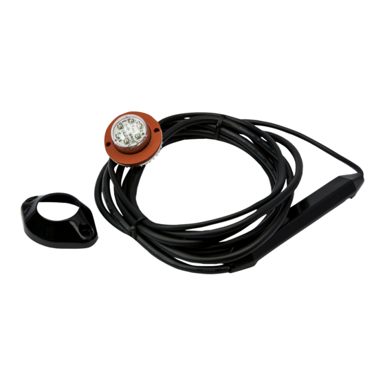
The 9014 Series Hide-A-LED™ provides exceptional warning capability in a compact light that
can be either mounted inside a head/tail light casing or surface mounted using the included
bezel. Using 6 high intensity LEDs the 9014 Series features 12 or 24 VDC operation, 16 flash
patterns, the ability to synchronize with additional units and a 9' cable.
IMPORTANT!
Read all instructions before installing and using. Installer: This manual must be delivered to the end user.
!
WARNING!
Failure to install or use this product according to manufacturers recommendations may result in property damage, serious injury, and/or death to
those you are seeking to protect!
Do not install and/or operate this safety product unless you have read and understand the safety information
contained
1.
Proper installation combined with operator training in the use, care, and maintenance of emergency warning devices are essential to ensure
the safety of you and those you are seeking to protect.
2.
Exercise caution when working with live electrical connections.
3.
This product must be properly grounded. Inadequate grounding and/or shorting of electrical connections can cause high current arcing,
which can cause personal injury and/or severe vehicle damage, including fire.
4.
Proper placement and installation are vital to the performance of this warning device. Install this product so that output performance of the
system is maximized and the controls are placed within convenient reach of the operator so that s/he can operate the system without losing
eye contact with the roadway.
5.
Do not install this product or route any wires in the deployment area of an air bag. Equipment mounted or located in an air bag deployment
area may reduce the effectiveness of the air bag or become a projectile that could cause serious personal injury or death. Refer to the
vehicle owner's manual for the air bag deployment area. It is the responsibility of the user/operator to determine a suitable mounting location
ensuring the safety of all passengers inside the vehicle particularly avoiding areas of potential head impact.
6.
It is the responsibility of the vehicle operator to ensure during use that all features of this product work correctly. In use, the vehicle operator
should ensure the projection of the warning signal is not blocked by vehicle components (i.e., open trunks or compartment doors), people,
vehicles or other obstructions.
7.
The use of this or any other warning device does not ensure all drivers can or will observe or react to a warning signal. Never take the right-
of-way for granted. It is your responsibility to be sure you can proceed safely before entering an intersection, driving against traffic, respond-
ing at a high rate of speed, or walking on or around traffic lanes.
8.
This equipment is intended for use by authorized personnel only. The user is responsible for understanding and obeying all laws regarding
warning signal devices. Therefore, the user should check all applicable city, state, and federal laws and regulations. The manufacturer as-
sumes no liability for any loss resulting from the use of this warning device.
Specifications:
Size:
Input Voltage:
12/24 VDC
Current Draw: 0.7A Max
Operating temperature range:
Lumens:
Installation & Mounting:
Before installation, examine the LED heads for transit damage. Do not use damaged or broken parts.
Important! This unit is a safety device, and it must be connected to its own separate, fused power point to assure its continued operation should any other
electrical accessory fail.
Lamp Mounting:
Pick a location in the vehicle lamp housing that is at least 1" away from any
existing bulbs. Drill 1" hole in vehicle lamp reflector housing with hole saw.
Mark the two screw hole locations and drill with 3/32" bit. Install the LED
head into lamp housing with gasket as shown in Figure 1. Use silicone RTV
on the screws to seal the threads.Strap the driver module to a nearby wire
harness or body structure. Make electrical connections as described below.
The LED heatsink will get hot during
1.28"
[32.51]
operation but will NOT melt any of the
plastic parts of the lens assembly.
DO NOT TOUCH the heatsink
during operation.
0.094"
[2.38]
3/32" DRILL
1.0"
[25.40]
MOUNTING HOLE
3.12"
[79.25]
DRIVER MODULE
DO NOT USE LED HEAD
WITHOUT DRIVER MODULE!
FIGURE 1
920-0211-01 Rev. C
0.87H x Dia. 1.51
-30 to +50ºC
9014A(Amber) 200
9014B(Blue) 100
9014R(Red) 200
9014C(Clear)460
LAMP MOUNTING
GASKET
1.505"
[38.23]
SCREWS
0.345"
[8.75]
0.175"
[4.45]
0.695"
[17.65]
MOUNTING
SURFACE
Installation Instructions
9014
Contents:
1 X HIDE-A-LED head with built-in power module and cable
1 X Mounting Gasket
2 X #6 X 1/2" Screws
1 X Bezel
Surface Mounting:
Mark and drill mounting hole locations in mounting surface. Make the
electrical connections described below and feed the driver module through
the mounting hole. Silicone RTV sealant should be used around the
mounting and screw holes. Install the bezel using the two screws provided.
1.8"
[45.72]
MOUNTING HOLE
0.688"
[17.46]
BEZEL OUTLINE
2.27"
[57.66]
DRIVER MODULE
DO NOT USE LED HEAD
WITHOUT DRIVER MODULE!
SURFACE MOUNTING
0.094"
[2.38]
3/32" DRILL
MOUNTING SURFACE
0.575"
[14.61]
1.65"
[41.91]
SCREWS
BEZEL
FIGURE 2
Page 1 of 8
Advertisement
Table of Contents

Subscribe to Our Youtube Channel
Related Manuals for Ecco Hide-A-LED 9014


Summary of Contents for Ecco Hide-A-LED 9014
- Page 1 Installation Instructions 9014 The 9014 Series Hide-A-LED™ provides exceptional warning capability in a compact light that can be either mounted inside a head/tail light casing or surface mounted using the included bezel. Using 6 high intensity LEDs the 9014 Series features 12 or 24 VDC operation, 16 flash patterns, the ability to synchronize with additional units and a 9’...
-
Page 2: Troubleshooting
Electrical Connections: RED: Connect to +V through an ON/OFF switch. The use of a fuse located close to the voltage source is recommended. Size the fuse according to the number of heads used in the system. 18AWG or larger wire is recommended. BLACK: Connect to - GROUND vehicle chassis. - Page 3 Instrucciones de instalación 9014 La Hide-A-LED™ Serie 9014 ofrece una excepcional capacidad de advertencia en una luz compacta que puede montarse dentro de las cajas de luces delanteras/traseras o en superficie mediante el bisel incluido. Usando 6 LED de alta intensidad, la Serie 9014 funciona con 12 o 24 V CC, tiene 16 patrones de intermitencia, capacidad de sincronizarse con unidades adicionales y un cable de 9 pies (2,7 m).
-
Page 4: Montaje En Superficie
Montaje de la lámpara: Montaje en superficie: Seleccione una ubicación en el alojamiento de la lámara del vehículo que esté a una distancia mínima Marque y perfore la ubicación de los orificios de montaje en la superficie de montaje. Realice las de 1 pulg. - Page 5 Limitación de responsabilidad y garantía limitada del fabricante: El fabricante garantiza que al momento de la compra, este producto cumple con las especificaciones del fabricante para el mismo (disponibles a pedido). El fabricante garantiza además que el presente producto está libre de defectos en sus materiales y en su fabricación. Esta garantía limitada se extiende durante veinte y cuatro (24) meses a partir de la fecha de la compra. Pueden aplicarse otras garantías.
- Page 6 Instructions d'installation 9014 La série 9014 Hide-A-LED™ dispose d'une capacité d'avertissement exceptionnelle au sein d'une lampe compacte qui peut être montée à l'intérieur du coffret d'un feu avant/arrière ou en surface à l'aide du cadran fourni. Avec ses six DEL à haute intensité, la série 9014 fonctionne à...
-
Page 7: Montage En Surface
Montage de la lampe : Montage en surface : Choisissez un endroit sur le boîtier de la lampe du véhicule qui soit à au moins 2,5 cm (1 po.) des Marquez l'emplacement des orifices de montage sur la surface de montage, puis percez les ampoules existantes. - Page 8 Garantie limitée et limitation de responsabilité du fabricant : Le fabricant garantit qu’à la date d’achat ce produit sera conforme aux caractéristiques techniques définies par ses soins (disponibles sur demande) et qu’il est exempt de vices de fabrication et de main- d’œuvre.
Need help?
Do you have a question about the Hide-A-LED 9014 and is the answer not in the manual?
Questions and answers