Table of Contents
Advertisement
Quick Links
IMPORTANT!
Read all instructions before installing and using. Installer: This manual must be
delivered to the end user.
!
WARNING!
Failure to install or use this product according to manufacturer's recommendations may result in property
damage, serious bodily/personal injury, and/or death to you and those you are seeking to protect!
Do not install and/or operate this safety product unless you have read and understand the safety
!
information contained in this manual.
1. Proper installation combined with operator training in the use, care, and maintenance of emergency warning devices are essential to
ensure the safety of emergency personnel and the public.
2. Emergency warning devices often require high electrical voltages and/or currents. Exercise caution when working with live electrical
connections.
3. This product must be properly grounded. Inadequate grounding and/or shorting of electrical connections can cause high current arcing,
which can cause personal injury and/or severe vehicle damage, including fire.
4. Proper placement and installation is vital to the performance of this warning device. Install this product so that output performance of
the system is maximized and the controls are placed within convenient reach of the operator so that s/he can operate the system with
out losing eye contact with the roadway.
5. It is the responsibility of the vehicle operator to ensure daily that all features of this product work correctly. In use, the vehicle operator
should ensure the projection of the warning signal is not blocked by vehicle components (i.e., open trunks or compartment doors),
people, vehicles or other obstructions.
6. The use of this or any other warning device does not ensure all drivers can or will observe or react to an emergency warning signal.
Never take the right-of-way for granted. It is your responsibility to be sure you can proceed safely before entering an intersection, drive
against traffic, respond at a high rate of speed, or walk on or around traffic lanes.
7. This equipment is intended for use by authorized personnel only. The user is responsible for understanding and obeying all laws
regarding emergency warning devices. Therefore, the user should check all applicable city, state, and federal laws and regulations.
The manufacturer assumes no liability for any loss resulting from the use of this warning device.
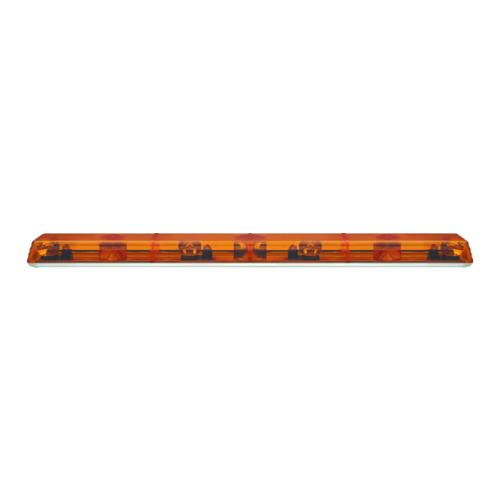
Introduction:
The ECCO Evolution Series are powerful, permanently mounted,
low-profile light bars available in several sizes.
Specifications:
Length
36"
Height
4.3"
Depth
8.5"
Weight
10 Lb
Input Voltage:
12 VDC system
Cable Length:
15' – 16'
Unpacking:
Carefully remove the light bar and place it on a flat surface. Examine
the unit for transit damage, and locate all parts. If damage is found,
or parts are missing, contact the transit company or ECCO. Do not
use damaged or broken parts.
920-0002-00 Rev. B
Installation and Operation Instructions
Evolution Series Light Bars (36"-72")
48"
54"
4.3"
4.3"
4.3"
8.5"
8.5"
8.5"
14 Lb
18 Lb
20 Lb
Important:
connected to its own, separate fused power point to
assure its continued operation should any other electrical
accessory fail.
!
60"
CAUTION!
make sure that the area is free from any electrical wires,
fuel lines, vehicle upholstery, etc. that could be damaged.
Installation & Mounting:
Permanent Mounting:
Before proceeding with installation, plan all wiring and cable
routing. Select the mounting location for the light bar on a flat,
smooth surface, light assembly should be centered (left to right). If
the light bar is to be mounted on a curved surface, such as on the
roof of the vehicle, choose a placement with the least amount of
curvature. The mounting location for the light bar should be chosen
such that there is maximum visibility to the oncoming traffic.
Use the following instructions for mounting (refer to Figure 1).
1. Position the mounting feet (without hardware) on the vehicle in
the desired location.
This unit is a safety device, and it must be
When drilling into any vehicle surface,
Page 1 of 8
Advertisement
Table of Contents

Subscribe to Our Youtube Channel
Related Manuals for Ecco Evolution Series


Summary of Contents for Ecco Evolution Series
- Page 1 If damage is found, roof of the vehicle, choose a placement with the least amount of or parts are missing, contact the transit company or ECCO. Do not curvature. The mounting location for the light bar should be chosen use damaged or broken parts.
-
Page 2: Wiring Instructions
.5 MIN. DETERMINED BY USER SHOULD BE SYMMETRICAL Figure 1 L I G H T B A R M O U N T I N G B O L T S M O U N T I N G F O O T R O O F ( C U T O U T ) F E N D E R W A S H E R S N Y L O C N U T S... - Page 3 2. Connect the power wires to the positive side of the appropriate lightbar switch or switches of the switch panel with quick CAUTION! disconnect terminals or by soldering. 3. After the light bar has been mounted, route the lightbar cable Disable power before wiring up the beacon/strobe into the vehicle to the switch panel location head, to prevent accidental shorting, arcing, and...
- Page 4 Four 360° Strobe Head Wiring Options ECCO Lightbars containing four 360° Strobe Head can be wired internally to achieve three different flash patterns. The three options are shown in Figures 3 (used if the bar has a single, 4-head power supply) and 4 (used if the bar has two 2-head power supplies). The default mode (i.e.
- Page 5 Figure 4 (Dual 2-Head Power Supplies 920-0002-00 Rev. B Page 5 of 8...
-
Page 6: Maintenance
3. Grip both the bulb and holder and pull apart. Do not stress the wire. 4. Replace bulb with a 12V, 55W H1 Halogen bulb (ECCO replacement p/n R5812BH). Do not touch the glass with bare hands. 5. Slide the bulb and holder back into position. -
Page 7: Work Lights
1. Facing the front of the reflector, push the bulb in slightly, and twist counter-clockwise. 2. Pull the bulb out. 3. In a reverse motion from steps 1 and 2, replace the bulb with a 12V, 50W Halogen 795 type bulb (ECCO replacement p/n R5012BH). Do not touch the glass with bare hands. -
Page 8: Exclusion Of Other Warranties
Lens Replacement Parts: Refer to Finished Goods Drawing. Manufacturer Limited Warranty and Limitation of Liability: Manufacturer warrants that on the date of purchase this product will conform to Manufacturer’s specifications for this product (which are available from the Manufacturer upon request), and Manufacturer further warrants that this product is free from defects in materials and workmanship.
Need help?
Do you have a question about the Evolution Series and is the answer not in the manual?
Questions and answers