
Related Manuals for SEFRAM MW3518


Summary of Contents for SEFRAM MW3518
- Page 1 USER'S MANUAL MW3518 2000A TRMS AC+DC Clamp Meter Dedicated for photovoltaic installations.
- Page 2 All meter models meet IEC/EN/BSEN/CSA_C22.2_No./UL standards of 61010-1 Ed. 3.1 and 61010-2-032 Ed. 4.0 to Measurement Categories CAT IV 1000V ac & dc. The model MW3518 additionally meets CAT III 1500V dc for Photovoltaic Power Generation applications. The accompanying test probe assembly meets IEC/EN/BSEN/CSA_C22.2_No./UL standards of 61010-031 Ed.
-
Page 3: International Symbols
INTERNATIONAL SYMBOLS Marking of Electrical and Electronic Equipment (EEE). Do not dispose of this product as unsorted municipal waste. Contact a qualified recycler. Refer to the explanation in this Manual Possibility of electric shock Earth (Ground) Meter protected throughout by Double Insulation or Reinforced insulation. Fuse Direct Current (DC) Alternating Current (AC) -
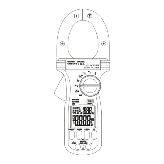
Page 4: Product Description
3) PRODUCT DESCRIPTION 1) Antenna for Non-Contact EF- Detection Hand/Finger Barrier indicate the limits of safe access meter during measurement 3) Rotary-switch Selector to turn the power ON/OFF and Select a function 4) Push-buttons for special functions & features. 5) Input Jack for all functions EXCEPT non-invasive DCA &... -
Page 5: Operation
4) OPERATION Note: Before and after hazardous voltage measurements, test the voltage function on a known source such as line voltage to determine proper meter functioning. VFD-ACV & ACV functions Inputs are made through the test lead terminals. VFD-ACV function is to deal with VFD (Variable Frequency Device) signals. It, however, further pre-selects the most appropriate voltage ranges and thus the Hz trigger levels to best cope with most VFD-Voltage and VFD-Frequency applications. - Page 6 , DCA & DC+ACA Input is made through the clamp jaws for non-invasive current measurements. Defaults at ACA Function. Press SELECT button momentarily and release to select the subject functions in sequence. Note: (Application and removal of the Clamp-on meter) For non-invasive current measurements, press the jaw trigger and clamp the jaws around conductor(s) of only one single pole of a circuit for load current measurement.
- Page 7 Resistance & Continuity functions Inputs are made through the test lead terminals. Defaults at Resistance. Press SELECT button momentarily and release to select. Continuity Capacitance & Diode functions Inputs are made through the test lead terminals. Defaults at Capacitance.
- Page 8 Temperature function Defaults at C (Celsius) readings. Press SELECT button momentarily and release to select F (Fahrenheit) readings. Inputs are made through the test lead terminals. Be sure to insert the banana plug type-K temperature bead probe with correct polarities. You can also use a plug adapter ST306 (Optional purchase) with banana pins to a type-K socket to adapt other type-K standard mini-plug temperature probes.
- Page 9 Electric Field EF-Detection In Voltage or Current function, press the EF button momentarily and release to toggle to EF-Detection feature. The meter displays “E.F.” when it is ready. Signal strength is indicated as a series of bar-graph segments on the display together with variable beep tones.
- Page 10 Hold The hold feature freezes the display for later views. Press the HOLD button momentarily and release to toggle the hold feature. 5ms CREST-MAX capture mode Press CREST (HOLD) button for one second or more and release to activate CREST- MAX capture (Instantaneous Peak-Hold) mode to capture signal peaks of voltage or current in duration as short as 5ms.
-
Page 11: Maintenance
the Auto-Power-Off (APO) feature. Turn the rotary switch OFF and then back on to resume. 5) MAINTENANCE Note: To avoid electrical shock, disconnect the meter from any circuit, remove the test leads from the input jacks and turn OFF the meter before opening the case. Do not operate with an open case. - Page 12 GENERAL SPECIFICATIONS Display: 3-5/6 digits 6000 counts & 3-1/2 digits 1,999 counts for Hz Polarity: Automatic Update Rate: 5 per second nominal; Operating Temperature: 0C to 40C Relative Humidity: Maximum relative humidity 80% for temperature up to 31C decreasing linearly to 50% relative humidity at 40C Pollution degree: 2 Storage Temperature: -20C to 60C, <...
- Page 13 3.1 & 61010-2-032 Ed. 4.0 to Measurement Categories CAT IV 1000V ac & dc. and CAT III 1500Vdc Transient Protection: 12kV (1.2/50s surge) Overload Protections: Clamp-on jaws: 2000A DC/AC rms continuous Voltage via terminals: 1650Vdc / 1100Vac rms Other functions via terminals: 1500Vdc / 1000Vac rms E.M.C.: Meets EN61326-1:2013 In an RF field of 3V/m: Capacitance function is not specified.
- Page 14 AC+DC Voltage Capacitance RANGE Accuracy RANGE Accuracy DC, 50Hz ~ 400Hz 60.00nF, 600.0nF, 6.000F 2.0%+5d 6.000V, 60.00V, 60.00F,600.0uF 3.5%+5d 1.4% + 7d 600.0V & 1000V 4.0%+5d 2000F Input Impedance: 10M, 50 pF nominal Accuracies with film capacitor or better Temperature Coefficient: 0.25 x (specified VFD_ACV (with Low Pass Filter) accuracy)/ C @ (0C -- 18C or 28C -- RANGE...
- Page 15 ACA Current (Clamp on) Hz Line Level Frequency Sensitivity RANGE Accuracy Function Range (Sine RMS) 50Hz ~ 60Hz 40Hz ~ 1999Hz 200.0A 2.0%+5d 40Hz ~ 1999Hz 0~500A 2.5%+5d 600V 100V 40Hz ~ 1999Hz 500~2000A 3.0%+5d 1000V 600V 40Hz ~ 1999Hz 40Hz ~ 50Hz &...
-
Page 16: Limited Warranty
SEFRAM's warranty does not apply to accessories, fuses, fusible resistors, spark gaps, batteries, or any product which, in SEFRAM's opinion, has been misused, altered, neglected, or damaged by an accident or abnormal condition of operation or handling.
Need help?
Do you have a question about the MW3518 and is the answer not in the manual?
Questions and answers