Table of Contents
Advertisement
Quick Links
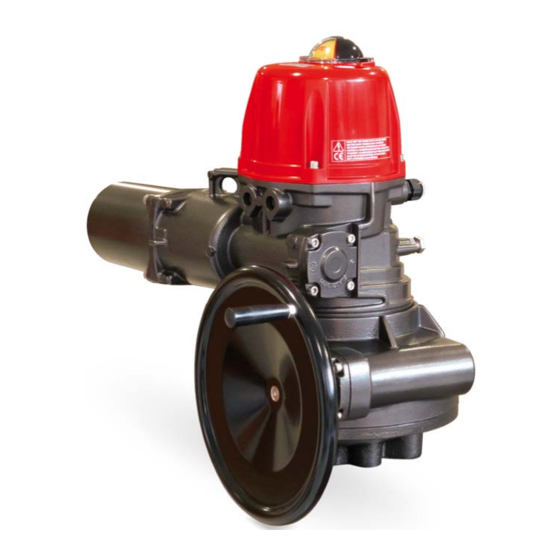
VT
Actionneur électrique
Manuel d'Installation et d'Utilisation
FR
Installation and Operation Manual
UK
Installations- und Bedienungsanleitung
DE
Manual de instalación y funcionamiento
ES
Valpes.com
Indice de protection
Facteur de marche
IP68
50%
Enclosure protection
Duty cycle
Anticondensation
intégrée
Anticondensation
heater
Advertisement
Table of Contents

Related Manuals for Watts Valpes VT Series


Summary of Contents for Watts Valpes VT Series
- Page 1 Actionneur électrique Manuel d’Installation et d’Utilisation Installation and Operation Manual Installations- und Bedienungsanleitung Manual de instalación y funcionamiento Anticondensation Indice de protection Facteur de marche intégrée IP68 Anticondensation Enclosure protection Duty cycle heater Valpes.com...
- Page 2 ENGLISH Français ........................2 English ........................12 Deutsch ........................22 Español ........................32 Index General information ...................... 13 Description Transport and storage Maintenance Warranty Return of goods Safety instructions Actuators description ....................14 Dimensions ........................15 Emergency manual override ..................15 Electric wiring ......................
-
Page 3: Maintenance
ENGLISH DESCRIPTION These electric actuators have been designed to perform the control of a valve with 90° rotation. Please consult us for any different application. We cannot be held responsible if the mentioned actuators are used for any other purpose. TRANSPORT AND STORAGE ... -
Page 4: Actuators Description
ENGLISH Actuators description Part Description Part Description Part Description 1 Visual position indicator 7 Aluminium support plate 13 Seal 2 Cover 8 O ring 14 Hand wheel 3 Stainless steel screws 9 O ring 15 O ring M20x1.5 threaded open- 4 Terminal strip 16 O ring ings... -
Page 5: Emergency Manual Override
ENGLISH Dimensions Sleeve Star (mm) Depth (mm) ISO F connection Diameter (mm) Treated M Depth (mm) Screws number Screws maximal length (+ valve connection plate height) (mm) 15mm 20mm 25mm Emergency manual override The actuator is set to its closed position in our factory and operates in electric priority. Ensure that the power supply is cut off prior to manually operation. -
Page 6: Electric Wiring
ENGLISH Electric wiring Warnings Dangerous Protection Direct Alternative voltage earth current current Use only one relay for one actuator. As stipulated in the applicable regulation, the connection to earth contact is compulsory for devices with working voltages exceeding 42V. ... - Page 7 ENGLISH Electric wiring: instructions SUPPLY AND CONTROL WIRING Remove the position indicator, unscrew the four screws and take off the cover. Ensure that the voltage indicated on the actuator ID label corresponds to the voltage supply. Connect the wires to the connector in accordance with the required control mode. (see diagram p. 18/19) ...
- Page 8 ENGLISH 230V electric diagram The terminal temperature can reach 90°C The used wires must be rigid (feedback voltages: 4 to 250V AC/DC) Rep. Designation Rep. Designation Rep. Designation FCO Open limit switch FCF Close limit switch TLO Torque switch : opening FC1 Auxiliary limit switch 1 FC2 Auxiliary limit switch 2 TLF Torque switch : closing...
- Page 9 ENGLISH 3-phase 400V electric diagram The terminal temperature can reach 90°C The used wires must be rigid (feedback voltages: 4 to 250V AC/DC) Designation Designation Designation Rep. Rep. Rep. Open limit switch Close limit switch Torque switch : opening Auxiliary limit switch 1 Auxiliary limit switch 2 Torque switch : closing...
-
Page 10: Technical Data
ENGLISH Technical data VT1500 VT2400 Location Housing: Aluminium + EPOXY paint / cover: PA6 UL 94 V-0 or Aluminium + EPOXY paint Materials Drive : Steel + Zn treatment / Axles and screws : Stainless steel Sealing IP68 Environment Both inside and outside (wet environments possible) Operating temperature -20°C to +70°C Operating altitude...
Need help?
Do you have a question about the Valpes VT Series and is the answer not in the manual?
Questions and answers