
Related Manuals for FrSky HORUS X12S


Summary of Contents for FrSky HORUS X12S
- Page 1 FrSky HORUS X12S Manual FrSky Electronic Co., Ltd. www.frsky-rc.com...
-
Page 2: User's Manual And Technical Support
Export and Trade Control Regulations and application must be submitted for export permission. 3. Repair, adjustment and replacement of parts: FrSky can not be held responsible for any unauthorized repair, adjustment and replacement of parts. All modifications to the product other... -
Page 3: Table Of Contents
Safe use and handling of Ni-MH batteries ................ 6 Operation norm of SD card ....................8 Before use ..........................8 Features of the HORUS X12S ..................... 8 Micro SD Card(Secure Digital memory card) ..............10 SYSTEM ............................ 12 MODEL SEL ........................13 TIME .......................... - Page 4 THROTTLE HOLD ......................322 THROTTLE CUT ......................322 THROTTLE MIX ......................333 SWASH RING........................333 PITCH→RUDDER ......................344 GYRO ..........................344 MODEL (FIXED-WING, GLIDER) ..................... 355 RATES/EXPO ........................355 THROTTLE CUT ......................355 THROTTEL HOLD ......................366 PITCH CURVE (FIXED-WING) ..................366 THROTTLE CURVE (EXCLUSIVE FOR FIXED-WING) ............
-
Page 5: Notes For Safe Use
Caution: read the following contents for your own or others’ safety; Carry out regular maintenance. The data of HORUS X12S is stored on SD card, the data can be not saved if the power is cut off directly, please follow the prompts when shut down the radio, and regular check shall be done. -
Page 6: Safe Use And Handling Of Ni-Mh Batteries
Safe use and handling of Ni-MH batteries Important The user can only use power adapter matching with FrSky or approved by FrSky to charge the battery of HORUS X12S transmitter. It is important to be aware about the discharge characteristics of Ni-MH battery. Please replace with info of used Ni-MH battery, battery in TX so need to open to read. - Page 7 Important notes Do not try to disassemble the Ni-MH battery pack. Keep the Ni-MH battery away from moisture or water at any time. Ensure ventilation when charging and discharging the Ni-MH batteries and in the process of use and storage. Someone must be present during the charging and discharging cycle of the Ni-MH batteries.
-
Page 8: Operation Norm Of Sd Card
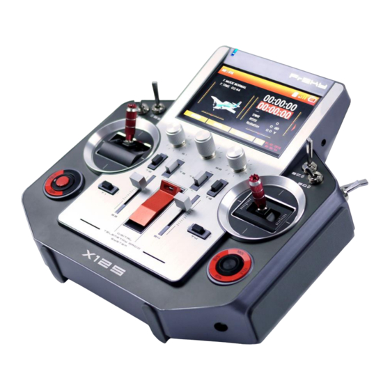
(L9R, etc.) The obsolete V8 series receiver is not compatible with the internal RF module, but can still be used in combination with an external DJT module. The LBT version of HORUS X12S only has FrSky D16 and LR12 Mode. - Page 9 Model types Helicopters models have six different types of swash plate modes. Fixed-wing aircraft have three modes, gliders have two modes and one multi-rotor mode. Besides this, there is also a fully custom model creation option. Display Industrial grade color display, high resolution (480x272), readable outdoor. Sticks CNC milled aluminum parts, fitted with 6 ball bearings in a single unit (2 on the return to center mechanism) combined with HALL sensors, for a superior feel of quality, precision and...
-
Page 10: Micro Sd Card(Secure Digital Memory Card)
You will find a variety of files such as videos, artworks for icons, voice files, detailed user guide, etc. on the pre-installed MicroSD card in HORUS X12S TF Card Slot. Be sure to turn off the power to the transmitter before inserting or removing the Micro SD card. - Page 11 Main interface The System menu is primarily used for setting up the system settings of the transmitter. Select the SYS key on the main interface to enter the interface of system settings menu. Main screen (page 1/3) The flight condition and total flight time are displayed on the top left of the screen and on the right side are two timers followed by real-time data related to the RF system.
-
Page 12: System
SYSTEM Overview of system menu Option list of system menu [MODEL SEL]: Is used to create new, select between, modify, copy or delete existing models. [TIME]: Is used to adjust the time, date and the order in which the date is displayed. [DISPLAY]: Allows adjustment to screen brightness and the option to assign a knob to manually adjust the intensity of the back-light. -
Page 13: Model Sel
MODEL SEL Select MODEL SEL in the system menu to enter the following menu selection. After selecting the menu, the name, model and model picture are displayed on the right of the screen and on the left is the operating part for model files. Select MODEL SEL to browse files of the existing models. -
Page 14: Time
TIME Select TIME in the system menu to enter the menu section illustrated below. Changes to the displayed time can be done in this menu. The user can also set and adjust date and time in accordance with region and time zone, the system can also display different date formats. -
Page 15: Music
SOUND Select SOUND in the system menu to enter the illustrated menu screen. You can adjust system sound volume according to personal preference, including on and off of key tone and system alerts (voice alarming), on and off of vibration, adjustment to volume and vibration intensity to meet different experience of diversified users, which is more personalized. -
Page 16: Battery
BATTERY Select BATTERY in the system menu to enter the illustrated menu screen. In the menu of this feature, the screen will display the current voltage of the transmitter battery, the user can also adjust the activation voltage of the low voltage protection alarm. The working range of the battery can be changed to keep a functional main-screen battery icon after installing a different type of battery. -
Page 17: Stk Cal
STK CAL Select STK CAL in the system menu to enter the illustrated menu screen. In the menu of this feature, the user can calibrate the sticks, knobs and sliders. We advise you to perform this task after each software update. -
Page 18: Stk (Knob) Dir
STK (KNOB) DIR Select STK DIR in the system menu to enter the illustrated menu screen. In the menu of this feature, the system displays hardware and type. The user can change "type" on all hardware inputs and adjust the direction of the corresponding signal to be able to set the required direction. -
Page 19: Trainer
TRAINER Select TRAINER in the system menu to enter the illustrated menu screen. In the menu of this feature, the user can choose the preferred connection methods, according to personal preference control can be claimed (Master) either via a switch or by directly overriding the controls. -
Page 20: Inf
The user can select wireless trainer mode in the top-left corner and select master or slave at “TYPE”(note: If you choose the wireless trainer mode, you need to choose “SLAVE” type and turn on the student’s transmitter firstly, then choose “MASTER” type and turn on the instructor’s transmitter ). -
Page 21: Rf System
Overview of the MODEL menu RF SYSTEM RF SYSTEM is divided into two segments, containing set up options for the internal IXJT and external RF module. The user can turn off the internal and external module during programming and/or simulator use, as well as choosing the receiver type and the amount of channels to be used. 1. -
Page 22: Servo Monitor
using it in more than one model. “Channel Range” can be used to select the amount of channels the user requires from the available internal IXJT module. The upper limit of the select-able channels in different modes depends on the amount and type of the used receiver. “STATE”... -
Page 23: Servo (Channel) Reverse
neutral position of a servo horn. Check the function of the channel, whether it is normal or not. Avoid programming the transmitter when the model is powered (-off) and/or running, this to avoid accidents caused by accidental spool up of the motor. SERVO (CHANNEL) REVERSE The user can reverse the direction of each individual channel, the PgUp and PgDn buttons can be used to switch between the menu pages. - Page 24 flaps, speed brakes etc. END POINT The “END POINT” menu is used to adjust the travel range and to set up differential on channels such as the ailerons. The end points of all 32 channels can be set up here, they are divided over 4 pages and are accessible via the PgUp and PgDn button.
-
Page 25: Sub Trim
SUB TRIM Illustrated above is an example of the “sub trim” menu, a total of 32 channels can be adjusted, they are divided over two pages and are accessible via the PgUp and PgDn buttons. This feature is used to set up the neutral position of the programmed hardware. A total range of -100 to +100 can be programmed, but if these high numbers are required, we advise you to check the hardware for proper installation. -
Page 26: Special Function
accidental spool up may happen if the transmitter switches off or if the signal connection is lost. Illustrated above is an example of the “fail safe” menu, a total of 32 channels can be adjusted, they are divided over 4 pages and are accessible via the PgUp and PgDn buttons. There are three modes available: HOLD, CUSTOM, and No Pulse. -
Page 27: Telemetry Set
allows an selection from the type of actions that can be assigned; the fourth column only comes active if the previous selected column has multiple options to choose from, here you can select sound and music files. TELEMETRY SET Illustrated above are examples of the “telemetry set” menu, a total of 37 sensors can be programmed, they are divided over 37 pages and are accessible via the PgUp and PgDn buttons. -
Page 28: Switch Warning
SWITCH WARNING Most users will assign switches to functions like landing gear, flaps and engine/motor cut-off. Turning on the transmitter with incorrect switch positions may lead to an accidental spool up of the motor and/or activation of the flaps/landing gears. In order to avoid these circumstances, we added a safety feature to the boot sequence of the transmitter which checks the position of the throttle and switches, this to generate a warning sign as well as pausing the boot up, if the programmed conditions are not met. -
Page 29: Output Map
OUTPUT MAP Illustrated above (on the previous page) is an example of the “output map” menu, a total of 32 channels can be assigned, they are divided over 4 pages and are accessible via the PgUp and PgDn buttons. Here the user can assign functions to the available channels, depending on the type and number receivers, up to 32 channels can be selected for a variety of tasks. -
Page 30: Model (Helicopter)
MODEL (HELICOPTER) RATES/EXPO Show on the illustration above is an example of the “rate/expo” menu, here the user can set up multiple deflection range rates and exponential on a variety of functions, and can be assigned to switches and/or flight modes. The throttle channel expo (curve) can be set up here and/or in the “throttle curve”... -
Page 31: Pitch Curve
PITCH CURVE Show on the illustration above is an example of the “pitch curve” menu, here the user can adjust the pitch curve on each individual flight mode to facilitate the required settings to ensure optimal operation. Open the function menu and on the interface of this function, the user can set different curves for pitch function on different flight conditions. -
Page 32: Throttle Hold
THROTTLE HOLD Open the throttle hold menu, of which the interface is as shown in the figure. When enabling the function, the user can set a fixed value for the output of the throttle. Place the throttle stick to the target position and the column bar on the right side will show the corresponding value. The users only have to fill the value in POS numerical box. -
Page 33: Throttle Mix
THROTTLE MIX Show on the illustration below is an example of the “throttle mix” menu, here the user can mix throttle with aileron, rudder and elevator. The user has 2 “rate” options and the possibility to assign the mix to a switch and/or flight mode. CAUTION! This feature involves the throttle channel, when using without the “THR cut”... -
Page 34: Pitch→Rudder
PITCH→RUDDER The change of main rotor pitch and revolution will lead to reaction torque. The function can effectively coordinate the output relationship between the pitch and the rudder to avoid head vibration of rudder direction and restrain the drift and out of control caused by reaction torque. The change of pitch stick will affect the output of rudder channel, so the function is not applicable for helicopters with the function of tail lock. -
Page 35: Model (Fixed-Wing, Glider)
MODEL (FIXED-WING, GLIDER) RATES/EXPO Under the mode of fixed-wing, the user can set five different rate curves for aileron, elevator and so on. Set corresponding switches on the receiver to control the switch and shift. The effective priority is D/R5 as highest and degrades from the bottom to the top. Under the mode of glider, the setting of dual rate is associated with flight mode (The setting of glider is similar to helicopter. -
Page 36: Throttel Hold
can quit the function only when the switch is in non-triggered position and the throttle is below critical value. THROTTEL HOLD The function of throttle hold can ensure fixed output of throttle. Open the menu and on the interface of this function, users can place the throttle stick to the target position and the columnar bar will show corresponding value. -
Page 37: Throttle Curve (Exclusive For Fixed-Wing)
THROTTLE CURVE (EXCLUSIVE FOR FIXED-WING) Shown on the illustration above is an example of the “thr curve” menu, here the user can adjust the throttle curve. It is used to adjust the correlation between the transmitters throttle stick position and the actual power units power setting. On gas/glow engines throttle curves can be used to get a linear throttle response, by increasing the movement of the throttle servo were the engine generates les torque and reducing the movement on the top end to get the linear feel in the stick. -
Page 38: Flap Set
Shown on the illustration above is an example of the “Ail DIFF” menu, here the user can adjust the travel range of each roll direction. Up to 4 aileron (or 2x aileron and 2x flaperon(camber flap)) channels can be programmed, to a range from -100 (reversed signal) to +100 (normal operation). The user shall make reasonable adjustment according to the actual installation of server and performance of different models when doing rolling movement. -
Page 39: Aileron→Camber Falp
corresponding channel, the settings of these two functions are on the same output signal, and will both be effected making changes. AILERON→CAMBER FALP Shown on the illustration above is an example of the “AIL-CMBFLP” mix menu, here the user can set up the flaperon mix. If the user experiences an insufficient roll rate during full aileron, deflection, or just wants to achieve the highest roll rate possible, the user can program flaps to function as ailerons (flaperons) via the “AILERON→CAMBER FALP—“... -
Page 40: Brake Flap→Camber Flap
Please refer to the previous section for more information, the setup procedure is identical to the AILERON→CAMBER FALP mix. BRAKE FLAP→CAMBER FLAP Shown on the illustration above is an example of the “BRKFLP-CMBFLP” mix menu, here the user can program the camber flaps to function as brake flaps, and assign it to a switch. If the user experiences insufficient effect of brake flap function, or just wants to achieve the highest possible braking effect, the option to mix in the camber flaps is available in this menu. -
Page 41: Rudder → Aileron
corrections to compensate for coupling. On some airplanes (depending on layout, airfoil type, etc.) a large coupling moment on the rudder (yaw) axis is generated when applying aileron, this due to the differential of frontal drag numbers generated by the difference in the created airfoil shapes (comparing LH and RH wing). -
Page 42: Rudder → Elevator (Fixed-Wing)
RUDDER → ELEVATOR (FIXED-WING) Shown on the illustration above is an example of the “RUD-ELE” mix menu, here the user can assign a switch, activate and adjust the mix intensity, this to compensate for coupling than may be generated on certain airplane/glider layout configurations. To enable changes to be made, the user must first activate the mix by selecting the ACT icon it the bottom right of the screen. -
Page 43: Cabmer Mix
CABMER MIX Shown on the illustration above is an example of the “CAMBER MIX” menu, here the user can assign a switch and mix elevator with ailerons (on all 4 channels). To enable changes to be made, the user must first activate the mix by selecting the ACT icon it the bottom right of the screen. The primary function of this feature is to compensate for the changing balance of the airplane/glider after extending de flaps. -
Page 44: Camber Flap → Elevator
enable changes to be made, the user must first activate the mix by selecting the ACT icon it the bottom right of the screen. The primary function of this feature is to either add lift or reduce lift during elevator operation. The positive lift effect can be used during takeoff and landings (may increase the susceptibility to a tip stall!), and reduce the turning radius of a loop. -
Page 45: V-Tail
you do not set a mechanical switch on the transmitter, the function will be always on by default. V-TAIL Shown on the illustration above is an example of the “V-TAIL” menu, here the user can program the V-tail airplane/glider mix. Up to 5 “flight modes” can be programmed, as well as changing the signal direction of the rudder and elevator. -
Page 46: Snap Roll (Fixed-Wing)
elevating force to reduce requirements to gliding speed and length of runway. On the interface of this function, the user can preset offset value for ailerons, flaps and elevators. CAUTION! Always check for correct system operation, after making changes to a flight control related mixes. Failure to do so can lead to unexpected system behavior, and may result in damage and/or serious injury. -
Page 47: Rudder Set (Glider)
This function provides the deflection setting for ailerons and elevators in different directions. The system offers twin elevator setting by default. In case the airplane is equipped with single vertical tail elevator, the user only has to set the preceding one. And the aileron can control on and off by itself. -
Page 48: Rate/Expo
RATE/EXPO Show on the illustration above is an example of the “rate/expo” menu, here the user can set up multiple deflection range rates and exponential on a variety of functions, and can be assigned to switches and/or flight modes. The throttle channel expo (curve) can be set up here and/or in the “throttle curve”... -
Page 49: Motor Curve (Glider)
and configure motor-on switch on the transmitter. If you do not select it, the function will be always on by default. MOTOR CURVE (GLIDER) Shown on the illustration below is an example of the “MOTOR CURVE” menu, here the user can assign a switch, adjust the throttle curve to make the throttle response linear on gas/glow engines, or set an idle speed on electric motors to prevent the motor from turning of during throttle blip-ping (pulsing). -
Page 50: Trim Mix (Glider)
TRIM MIX (GLIDER) Shown on the illustration above is an example of the “TRIM MIX” menu, here the user can set up the required trim depending on the corresponding “flight mode”. The user must first activate the mix by selecting the ACT icon it the bottom right of the screen. The primary function of this menu feature is to accommodate multiple trim setting depending on the selected “flight mode”, giving the user the option to trim each mode depending on the requirements. -
Page 51: Throttel Curve
“throttle curve” menu depending on the selected model type. After opening the function menu, the user can set rate for ailerons, elevators and rudders according to different flight modes. When switching to this mode, the function takes effect automatically (default) and the user can configure a switch on the transmitter to enable the effectiveness of the function. -
Page 52: Mode
MODE The transmitter supports up to five individual flight modes, the priority order goes from top to bottom, the user can assign switches to change between modes but we recommend to use the 5 position M-POS knob. CAUTION! Always check for correct system operation, after making changes to a flight control related features. -
Page 53: Model (Custom Mix)
MODEL (CUSTOM MIX) MIXER In order to meet the demands of different players and fulfill flight mission of customized models, the user can customize mixer configuration to achieve personalized operation and fancy playing and greatly enhance flight experience. The user can edit 32 mixers in total from MIXER1 to MIXER32 and switch to different mixers through PgUp and PgDn. - Page 54 Interface 1 The interface is about some basic settings of the slot, which from the top to the bottom are ENABLE - control the effectiveness of the; SRC – the control source of the slot; SW - enable switch; METHROD- algorithm of mixer control and FLIGHT CON- flight mode. The flight mode and SW has a relationship of “and”, which means the slot will take effect and participate in the algorithm of mixer control only when the switch is on and it is in corresponding flight mode.
- Page 55 Interface 3 The third interface is for the setting of OFFSET values for five groups. The setting and execution relationship is basically the same as interface 2. Interface 4 This interface is for the setting of five curves for the slot and the curves are directly called, which need to be edited in CURVE LIB and other settings and execution relationship is basically the same as interface 2.
-
Page 56: Output Map
OUTPUT MAP The user can freely define mixers which have been edited to certain channels for output, which is more convenient when the consequence of output needs to be changed. (It is basically consistent with OUTPUT MAP in normal modes. (See general function/ output map). LOGIC SWITCH The user can set two sources involved in logical algorithm, which can be on/off status, values... -
Page 57: Special Function
of channels etc. and select the method of logic algorithm and then a logic switch is created. When the result of logic algorithm is true, the corresponding logic switch will be on. SPECIAL FUNCTION Same as special function in normal modes. (See general function/special function) CURVE LIB The user can preset a number of curves for direct call on mixer editing interface, which can eliminates the trouble of creating curves and save lots of energy and time.
Need help?
Do you have a question about the HORUS X12S and is the answer not in the manual?
Questions and answers