National Instruments IC-3173 User Manual
Industrial controller with reconfigurable i/o
Hide thumbs
Also See for IC-3173:
- Getting started manual (14 pages) ,
- User manual (59 pages) ,
- User manual (36 pages)
Table of Contents
Advertisement
Quick Links
USER MANUAL
IC-3173
Industrial Controller with Reconfigurable I/O
This document contains detailed electrical and mechanical information for the National
Instruments IC-3173.
Contents
About the IC-3173.................................................................................................................... 1
Hardware Overview.................................................................................................................. 2
Connector Pinouts............................................................................................................. 3
LED Indicators................................................................................................................ 15
Using the RESET Button................................................................................................ 18
Replacing the Battery......................................................................................................18
Mounting the IC-3173.............................................................................................................19
Securing the IC-3173 to a Mount....................................................................................22
Clearance Requirements................................................................................................. 24
Software Options.....................................................................................................................25
BIOS Configuration and System Recovery............................................................................ 25
Entering BIOS Setup.......................................................................................................25
BIOS Setup Utility Keyboard Navigation...................................................................... 25
Main Setup Menu............................................................................................................26
Advanced Menu.............................................................................................................. 27
Boot Menu.......................................................................................................................29
Save & Exit Menu...........................................................................................................30
Restoring the Device to Factory Default Condition........................................................31
Where to Go Next................................................................................................................... 31
Resources for LabVIEW Users.......................................................................................31
Resources for Vision Builder AI Users...........................................................................32
About the IC-3173
The IC-3173 is a high-performance, small, fanless embedded computer designed for rugged
industrial applications. The IC-3173 also provides multiple digital input/output (I/O) options
for communicating with external devices.
Advertisement
Table of Contents

Subscribe to Our Youtube Channel
Related Manuals for National Instruments IC-3173


Summary of Contents for National Instruments IC-3173
-
Page 1: Table Of Contents
Resources for LabVIEW Users..................31 Resources for Vision Builder AI Users................32 About the IC-3173 The IC-3173 is a high-performance, small, fanless embedded computer designed for rugged industrial applications. The IC-3173 also provides multiple digital input/output (I/O) options for communicating with external devices. -
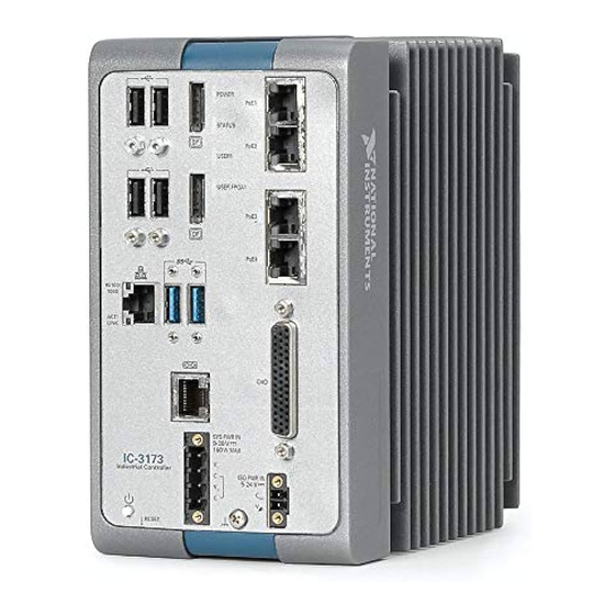
Page 2: Hardware Overview
Hardware Overview The IC-3173 front panel consists of four Gigabit Ethernet ports with Power over Ethernet (PoE), one RS-232/RS-485 serial port, one standard Gigabit Ethernet Port, two USB 3.0 ports, four USB 2.0 ports, and two DisplayPort connectors. The IC-3173 front panel also includes LEDs for communicating system status and a 44-pin Digital I/O port. -
Page 3: Connector Pinouts
You can develop a single real-time VI to use for both your user interface and system logic. For more information, refer to the Using the Embedded UI to Access RT Target IC-3173 User Manual | © National Instruments | 3... - Page 4 Figure 2. DisplayPort Connector Pin Locations Table 1. DisplayPort Connector Pin Descriptions Signal Name ML_Lane0(p) ML_Lane0(n) ML_Lane1(p) ML_Lane1(n) ML_Lane2(p) ML_Lane2(n) ML_Lane3(p) ML_Lane3(n) CONFIG1 CONFIG2 AUX CH (p) AUX CH (n) Hot Plug Detect 4 | ni.com | IC-3173 User Manual...
- Page 5 If a PoE-capable device is plugged into an Ethernet port with PoE, the IC-3173 automatically supplies power to the device. When the IC-3173 supplies PoE, the LED that corresponds to the port illuminates. When you unplug a PoE device, PoE is automatically disabled. You can use non-PoE Ethernet devices with the PoE-enabled Gigabit Ethernet ports.
- Page 6 BI_DC- Digital I/O The 44-pin Digital I/O port on the IC-3173 offers 8 isolated inputs, 8 isolated outputs, 2 bidirectional differential inputs (RS-422) or single-ended input lines that can be used with a quadrature encoder, and 8 bidirectional TTL lines. The Digital I/O port can be connected to any appropriate shielded device or connector block using a shielded cable.
- Page 7 Diff 1- Bidirectional RS-422 I/O Isolated power voltage reference output Common ground reference for isolated inputs and outputs Iso Out 2 General purpose isolated output Iso Out 3 General purpose isolated output IC-3173 User Manual | © National Instruments | 7...
- Page 8 Common ground reference for isolated inputs and outputs Iso Out 6 General purpose isolated output Iso Out 7 General purpose isolated output Wiring an Isolated Input You can wire an isolated input to a sourcing output device. 8 | ni.com | IC-3173 User Manual...
- Page 9 Use this protection method if you connect any of the isolated outputs on the IC-3173 to an inductive load. The following image shows an example of an isolated output wired to an external load with a flyback diode installed across the load.
- Page 10 Inductive Loads Connecting to Differential I/O The IC-3173 accepts differential (RS-422) line driver inputs. Each of the two differential I/O can be configured as an output. Use shielded cables for all applications. Unshielded cables are more susceptible to noise and can corrupt signals.
- Page 11 Figure 8. Connecting Differential Line Drivers External Device Industrial Controller Diff In 0+ Phase A Twisted Pair – Diff In 0– Phase A Diff In 1+ Phase B Twisted Pair – Diff In 1– Phase B IC-3173 User Manual | © National Instruments | 11...
- Page 12 TTL I/O TTL_IN Power Input Connectors The IC-3173 requires a power supply to power the system and, if you want to use the isolated outputs, a power supply to power the isolated outputs. Table 4. System Power Connector Terminals Terminal...
- Page 13 RS-485/422/232 Serial Port The IC-3173 has a single serial port that can operate in either RS-485/422 mode or RS-232 mode. Set the serial port mode in the BIOS setup utility. The serial port is a 10-position RJ50 modular jack, which can connect to serial devices, such as PLCs, scanners, and lighting devices.
- Page 14 /U drive if it is available. Refer to the LabVIEW Help for more information. Figure 12. USB 3.0 Port Pin Locations Table 7. USB 3.0 Port Pin Descriptions Signal Name Signal Description VBUS Cable Power (+5 VDC) USB Data - 14 | ni.com | IC-3173 User Manual...
-
Page 15: Led Indicators
USB Data - USB Data + Ground for power return LED Indicators The LED indicators are located on the front panel of the device. The IC-3173 provides the following LED indicators. POWER LED The following table lists the POWER LED indications. - Page 16 The IC-3173 has experienced two consecutive software exceptions. The IC-3173 automatically restarts after an exception. After the second exception, the IC-3173 remains in the exception state, alerting you to resolve the problem. Reinstall software on the IC-3173 or contact National Instruments.
- Page 17 Figure 14. LEDs for the Gigabit Ethernet Ports 1. Speed LED 2. Activity/Link LED Table 13. Ethernet LED Indications Status Indication No link, or 10 Mbps link Speed Green 100 Mbps link Amber 1,000 Mbps link IC-3173 User Manual | © National Instruments | 17...
-
Page 18: Using The Reset Button
TCP/IP settings are invalid. When the IC-3173 is in the IP reset state, the IP address of the network port resets to DHCP or a link-local address. You can then set up a new network configuration for the IC-3173 from a development machine on the same subnet, or you can connect the IC-3173 directly to the development computer. -
Page 19: Mounting The Ic-3173
Mounting the IC-3173 This section provides information for creating a custom mount for the IC-3173. If you do not want to create a custom mount, a panel mount kit for the IC-3173 is available from National Instruments (part number 784791-01). - Page 20 5-24 V 27.94 mm 21.35 mm (1.10 in.) (0.84 in.) 11.45 mm 22.72 mm (0.45 in.) (0.89 in.) 36.12mm 3.27 mm (1.42 in.) (0.129 in.) 2.58 mm (0.10 in.) 28.02 mm (1.10 in.) 20 | ni.com | IC-3173 User Manual...
- Page 21 Figure 16. Side View Dimensions 167.63 mm (6.60 in.) 4.23 mm 15.08 mm (0.17 in.) (0.20 in.) 173.99 mm (6.85 in.) 176.94 mm (6.97 in.) IC-3173 User Manual | © National Instruments | 21...
-
Page 22: Securing The Ic-3173 To A Mount
Align the screw holes of the mounting bracket with the four holes on the back of the IC-3173. Insert four 6-32 screws and tighten them 0.28 N · m (3.5 lb · in) until they are secure. Ensure the heads of the screws are flush with the mounting bracket. 22 | ni.com | IC-3173 User Manual... - Page 23 Figure 18. Securing a Mounting Bracket to the Device IC-3173 User Manual | © National Instruments | 23...
-
Page 24: Clearance Requirements
The IC-3173 installation must meet the following space and cabling clearance requirements for optimum cooling: • Allow 101.6 mm (4.0 in.) on the top and bottom of the IC-3173 for air circulation. • Allow 50.8 mm (2.0 in.) on the sides of the IC-3173 for air circulation. -
Page 25: Software Options
IC-3173 FPGA. BIOS Configuration and System Recovery You can change the configuration settings for the IC-3173 in the BIOS setup utility. The BIOS is the low-level interface between the hardware and PC software that configures and tests your hardware when you boot the system. The BIOS setup utility includes menus for configuring settings and enabling features. -
Page 26: Main Setup Menu
In the BIOS menu, use <+> and <-> in conjunction with <Enter> and <Tab> to change these values. You can also change these settings using NI-MAX or Vision Builder • System Date—This value controls the date. • System Time—This value controls the time of day. 26 | ni.com | IC-3173 User Manual... -
Page 27: Advanced Menu
Serial Port Configuration SATA Configuration Submenu Use this submenu to apply custom configurations to the internal disk drive of the IC-3173. Normally, you do not need to modify these settings, as the factory default settings provide the most compatible and optimal configuration. - Page 28 Valid values are Stay Off and Turn On. The default value is Turn On. When set to Stay Off, the IC-3173 returns to the soft off power state after power is restored. When set to Turn On, the IC-3173 powers on when power is restored.
-
Page 29: Boot Menu
RS-485 Configuration—Use this menu to configure the RS-485/422 wire-mode. The default value is Auto. Boot Menu This screen displays the boot order of devices associated with the IC-3173 and allows you to configure the boot settings. The Boot setup menu includes the following submenus: •... -
Page 30: Save & Exit Menu
Restore User Defaults—This option restores all BIOS settings to the values last saved as user defaults. • Boot Override—This option lists all possible bootable devices and allows the user to override the Boot Option Priorities list for the current boot. If no changes have been 30 | ni.com | IC-3173 User Manual... -
Page 31: Restoring The Device To Factory Default Condition
Start the IC-3173 in safe mode. To start in safe mode, apply power, turn on the device, press the RESET button for more than 5 seconds, then release the button. -
Page 32: Resources For Vision Builder Ai Users
Vision Builder AI. You can access the NI Vision Builder for Automated Inspection Tutorial and other documentation by selecting Start»All Programs» National Instruments»Vision Builder AI»Documentation. You can also access context help within Vision Builder AI by clicking the Show Context Help button on the Vision Builder AI toolbar.
Need help?
Do you have a question about the IC-3173 and is the answer not in the manual?
Questions and answers