
Related Manuals for National Instruments IC-3121


Summary of Contents for National Instruments IC-3121
- Page 1 National Instruments IC-3121 Manual Get Pricing & Availability at ApexWaves.com Call Today: 1-800-915-6216 Email: sales@apexwaves.com https://www.apexwaves.com/modular-systems/national-instruments/industrial-controllers/IC-3121...
-
Page 2: Table Of Contents
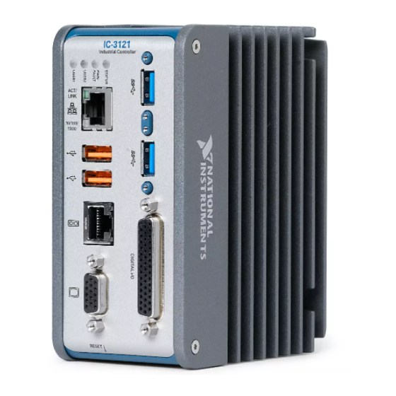
Worldwide Support and Services.................... 32 Hardware Overview The IC-3121 front panel consists of a VGA port, RJ50 serial port, two USB 2.0 ports, a 10/100/1000 Ethernet port, and two USB 3.0 ports. The IC-3121 front panel also includes LEDs for communicating system status and a 44-pin Digital I/O port. -
Page 3: Connector Pinouts
Chassis Grounding Screw Use the grounding screw to connect the chassis to earth ground. An earth ground connection is optional. Note An earth ground connection does not connect C or C to earth ground. 2 | ni.com | IC-3121 User Manual... - Page 4 1. Chassis Grounding Screw Power Input Connectors The IC-3121 requires a power supply to power the system. If needed for your application, an additional power source is required to power the isolated outputs. The same power supply may be used for both the system power and isolated outputs power if isolation is not required and the power supply meets the voltage and power requirements for both inputs.
- Page 5 Power for isolated outputs (5-24 VDC) Ethernet Port The IC-3121 provides a Gigabit Ethernet port. The Ethernet port provides a connection between the IC-3121, a network, and other Ethernet devices. The IC-3121 automatically detects the speed of the connection and configures itself accordingly.
- Page 6 (RT only) LabVIEW usually maps USB mass-storage devices to the /U, /V, /W, or /X drive, starting with the /U drive if it is available. Refer to the LabVIEW Help for more information. Figure 5. USB 2.0 Pin Locations IC-3121 User Manual | © National Instruments | 5...
- Page 7 Ground for power return RS-485/422/232 Serial Port The IC-3121 has a single serial port that can operate in either RS-485/422 mode or RS-232 mode. Set the serial port mode in the BIOS setup utility. The serial port is a 10-position RJ50 modular jack, which can connect to serial devices, such as PLCs, scanners, and lighting devices.
- Page 8 21 VGA Port Use the VGA port to connect a monitor to the IC-3121. Use any standard 15-pin VGA cable to access the VGA port. The VGA port has a maximum resolution of 1920 x 1200 at 60 Hz.
- Page 9 Table 5. USB 3.0 Port Pin Descriptions Signal Name Signal Description VBUS Cable Power (+5 VDC) USB Data - USB Data + Ground for power return StdA_SSRX- SuperSpeed receiver differential pair StdA_SSRX+ GND_DRAIN Ground for signal return 8 | ni.com | IC-3121 User Manual...
- Page 10 StdA_SSTX+ Digital I/O The 44-pin Digital I/O port on the IC-3121 offers 8 isolated inputs, 8 isolated outputs, 2 bidirectional differential inputs (RS-422) or single-ended input lines that can be used with a quadrature encoder, and 8 bidirectional TTL lines. The Digital I/O port can be connected to any appropriate shielded device or connector block using a shielded cable.
- Page 11 Common ground reference for isolated inputs and outputs Iso Out 2 General purpose isolated output Iso Out 3 General purpose isolated output Common ground reference for isolated inputs and outputs Iso Out 5 General purpose isolated output 10 | ni.com | IC-3121 User Manual...
- Page 12 Do not allow the voltage on the isolated inputs to exceed 30 VDC. Doing so will damage the IC-3121. Figure 10. Connecting an Isolated Input to a Sourcing Output Device Power Supply Input Current Limiter Sourcing Output Device – Industrial Controller IC-3121 User Manual | © National Instruments | 11...
- Page 13 Inductive Loads Connecting to Differential I/O The IC-3121 accepts differential (RS-422) line driver inputs. Each of the two differential I/O can be configured as an output. Use shielded cables for all applications. Unshielded cables are more susceptible to noise and can corrupt signals.
- Page 14 Figure 13. Connecting Differential Line Drivers External Device Industrial Controller Diff In 0+ Phase A Twisted Pair – Diff In 0– Phase A Diff In 1+ Phase B Twisted Pair – Diff In 1– Phase B IC-3121 User Manual | © National Instruments | 13...
-
Page 15: Led Indicators
The following image shows the circuit for a bidirectional TTL I/O. Figure 15. TTL Input/Output Circuit 10 kΩ TTL_OUT 100 Ω TTL_OE TTL I/O TTL_IN LED Indicators The IC-3121 provides the following LED indicators. 14 | ni.com | IC-3121 User Manual... - Page 16 Figure 16. LED Indicators IC-3121 Industrial Controller RESET The following table describes the LEDs and indications. IC-3121 User Manual | © National Instruments | 15...
- Page 17 IC-3121. Reinstall software on the IC-3121. 3 blinks (RT only) The IC-3121 has booted into safe mode. Refer to the Safe Mode section for information about the safe mode state. 4 blinks (RT only) The IC-3121 has experienced two consecutive software exceptions.
- Page 18 Table 7. LED Indications (Continued) LED State Indication Color PWR/ — The IC-3121 is OFF. This is not an indication of FAULT whether power is applied or not. Green Solid The IC-3121 is operating normally and is properly powered on.
-
Page 19: Using The Reset Button
TCP/IP settings are invalid. When the IC-3121 is in the IP reset state, the IP address of the network port resets to DHCP or a link-local address. You can then set up a new network configuration for the IC-3121 from a... -
Page 20: Software Options
IC-3121 FPGA. BIOS Configuration and System Recovery You can change the configuration settings for the IC-3121 in the BIOS setup utility. The BIOS is the low-level interface between the hardware and PC software that configures and tests your hardware when you boot the system. The BIOS setup utility includes menus for configuring settings and enabling features. -
Page 21: Bios Keyboard Navigation
The Advanced setup menu includes the following submenus: • Power/Wake Configuration • Serial Port Configuration • SATA Configuration • USB Configuration 20 | ni.com | IC-3121 User Manual... -
Page 22: Boot Menu
6 SATA Configuration Submenu Use this submenu to apply custom configurations to the processor of the IC-3121. Normally, you do not need to modify these settings, as the factory default settings provide the most compatible and optimal configuration possible. - Page 23 The highest priority device is displayed on the main Boot Option Priorities list. Optionally, each device can also be Disabled if the device should never be used as a boot device. 22 | ni.com | IC-3121 User Manual...
-
Page 24: Save & Exit Menu
BIOS setup options, the system will continue booting to the selected device without first rebooting. If BIOS setup options have been changed and saved, a reboot is required and the boot override selection will not be valid. IC-3121 User Manual | © National Instruments | 23... -
Page 25: Restoring The Ni Linux Real-Time Operating System
You can create a bootable USB flash drive from the reinstallation DVD if you do not have a USB DVD drive to connect to the IC-3121. The USB flash drive must be at least 8 GB. Ensure the USB flash drive appears as a Removable Drive in Windows. Avoid using drives that appear as Fixed Disk drives. - Page 26 Complete the following steps to use the recovery media to install Windows. Connect the bootable USB flash drive to one of the USB ports on the IC-3121. Or connect an external DVD drive to one of the USB ports on the IC-3121 and insert the recovery DVD into the external drive.
-
Page 27: Mounting The Ic-3121
This section provides information for creating a custom mount for the IC-3121. If you do not want to create a custom mount, a panel and DIN rail mount kit for the IC-3121 is available from National Instruments (part number 781740-01). - Page 28 (0.674 in.) (1.605 in.) 26.78 mm (1.054 in.) 38.75 mm (1.526 in.) 27.56 mm (1.085 in.) 21.19 mm (0.834 in.) 15.07 mm (0.593 in.) 24.71 mm (0.973 in.) 60.96 mm (2.400 in.) IC-3121 User Manual | © National Instruments | 27...
- Page 29 Figure 20. Back View with Dimensions in inches [millimeters] 23.46 mm 37.50 mm (0.924 in.) (1.476 in.) 19.41 mm (0.764 in.) 54.48 mm (2.145 in.) 23.24 mm (0.915 in.) 24.46 mm 25.92 mm (0.963 in.) (1.020 in.) 10.58 mm (0.417 in.) 28 | ni.com | IC-3121 User Manual...
- Page 30 Figure 21. Side View with Dimensions in inches [millimeters] 3.80 mm (0.150 in.) 104.67 mm (4.121 in.) 130.38 mm (5.133 in.) 108.47 mm (4.270 in.) IC-3121 User Manual | © National Instruments | 29...
-
Page 31: Securing The Ic-3121 To A Mount
The IC-3121 installation must meet the following space and cabling clearance requirements for optimum cooling: • Allow 76.2 mm (3.0 in.) on the top and bottom of the IC-3121 for air circulation. • Allow 50.8 mm (2.0 in.) on the sides of the IC-3121 for air circulation. -
Page 32: Where To Go Next
Where to Go Next The following documents and resources contain information you may find helpful as you use the IC-3121 in an application. Refer to the National Instruments Product Manuals Library at ni.com/manuals for the most recent versions of product documentation. -
Page 33: Worldwide Support And Services
CONTAINED HEREIN AND SHALL NOT BE LIABLE FOR ANY ERRORS. U.S. Government Customers: The data contained in this manual was developed at private expense and is subject to the applicable limited rights and restricted data rights as set forth in FAR 52.227-14, DFAR 252.227-7014, and DFAR 252.227-7015. © 2016 National Instruments. All rights reserved. 376111A-01 Apr16...
Need help?
Do you have a question about the IC-3121 and is the answer not in the manual?
Questions and answers