Table of Contents
Advertisement
- Data Brochure
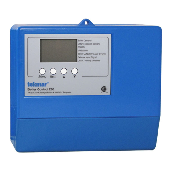
Boiler Control 265
The tekmar Boiler Control 265 can control the supply water temperature on up to three modulating boilers based on outdoor
temperature or setpoint requirements. The control can be set to control up to two modulating boilers based on outdoor temperature
or domestic hot water requirements. A large easy to read display provides current system temperatures and operating status. The
control has outputs for a primary pump, individual boiler pumps, and either a combustion air damper or an alert.
Additional functions include:
•
Outdoor Reset
•
Sequential or Parallel Modulation
•
Installer and Advanced access levels
•
Primary pump output
•
Individual boiler pump outputs
•
Pump purging
•
Boiler demand for space heating loads
Boiler Control 265
Three Modulating Boiler & DHW / Setpoint
Do not apply power
1
2
Input
Com
Boil
Universal
–
Sup
Sensor
Included
Input
Universal
Sensor
Included
Input
Outdoor
Sensor
Included
or
Input
Input
0-10 V (dc)
Timer or Switch
External Signal
Optional
Menu
Item
3
4
5
6
7
8
9 10 11
12 13
Boil
Out
UnO
Mod1 mA
Mod2 mA
Mod3 mA
Prim
Ret
+
Sw
+
–
+
–
+
–
Output
Output
Modulating
Modulating
Boiler
Boiler
•
DHW demand for domestic hot water loads
•
Setpoint demand for setpoint loads
•
0 – 10 V (dc) BAS / EMS input
•
Test sequence to ensure proper component operation
•
Setback input for energy savings
•
CSA C US certified
•
Pump exercising
External Input
Advanced
Boiler Demand
DHW / Setpoint Demand
Installer
Stand Alone
WWSD
Modulation
Boiler Output (x10,000 BTU/hr)
External Input Signal
Offset / Priority Override
Made in Canada by
tekmar Control Systems Ltd.
Power
Relays
Demands
Signal wiring must be rated at least 300 V.
14
15 16 17
18
19
20
21 22 23 24 25 26 27 28 29
C.A./
Boiler 3 /
Power
Boiler
Boiler
P1
L
N
Alert
1
1
2
2
DHW
Pump 1
Output
Output
Modulating
Primary
Boiler
Pump
Power Supply
1 of 36
Parallel
Alert
Off
Soft Stop
Rotate
Fixed Lead
First On / Last Off
First On / First Off
CA.
Off
Exercise
Sequential
Test
115 V ±10% 60 Hz 600 VA
230 V (ac) 5 A 1/3 hp, pilot duty 240 VA
20 to 260 V (ac) 2 VA
30
31
Boiler
Boiler
Boiler
Boil
Com
Setp/
Pump 2
Pump 3
Dem
Dem
DHW
or
Input
Output
115 V (ac)
Combustion Air
or Alert
© 2010
D 265
07/10
Note:
Boiler, DHW,
or setpoint
demand must
be powered with
20 to 260 V (ac)
before the boiler
is able to fire.
Input
Setpoint
or DHW
Demand
Input
Boiler
Demand
Output
Pump
Output
Boiler
Enable
or
Pump
Output
Boiler
Enable
D 265 - 07/10
Advertisement
Table of Contents

Subscribe to Our Youtube Channel
Related Manuals for Tekmar Boiler Control 265


Summary of Contents for Tekmar Boiler Control 265
- Page 1 07/10 The tekmar Boiler Control 265 can control the supply water temperature on up to three modulating boilers based on outdoor temperature or setpoint requirements. The control can be set to control up to two modulating boilers based on outdoor temperature or domestic hot water requirements.
-
Page 2: Table Of Contents
How To Use The Data Brochure This brochure is organized into four main sections. They are: 1) Sequence of Operation, 2) Installation, 3) Control Settings, and 4) Testing and Troubleshooting. The Sequence of Operation section has seven sub-sections. We recommend reading Section A: General of the Sequence of Operation, as this contains important information on the overall operation of the control. -
Page 3: Display
Display Menu Field Number Field Displays the Displays the current value of the selected item current menu Item Field Displays an abbreviated name of the selected item Status Field Displays the Buttons current status Selects Menus, Items of the control's and adjust settings inputs, outputs and operation... -
Page 4: Sequence Of Operation
Definitions The following defined terms and symbols are used throughout this manual to bring attention to the presence of hazards of various risk levels, or to important information concerning the life of the product. - Warning Symbol: Indicates presence of hazards which can cause severe personal injury, death or substantial property damage if ignored. - Page 5 SETBACK (OCC and UNOCC) To provide greater energy savings, the control has a setback feature. With setback, the supply water temperature in the system is reduced when the building is unoccupied. By reducing the supply water temperature, the air temperature in the space may be reduced even when thermostat(s) are not turned down.
-
Page 6: Section B: Boiler Operation
EXERCISING The control has a built-in exercising feature that is selected through the Exercise / Off DIP switch. To enable the exercising feature set the Exercise / Off DIP switch to Exercise. If exercising is enabled, the control ensures that each pump is operated at least once every 3 days. - Page 7 MODULATION RANGE (4 to 20 mA or 0 to 20 mA) The modulation output (Mod 1, Mod 2, and Mod 3) for each boiler can be adjusted from a 4 to 20 mA output range to a 0 to 20 mA output range using the Boil Modulation 1, Boil Modulation 2, or Boil Modulation 3 setting.
- Page 8 Example 1: A boiler’s input signal range is 2 to 9 V (dc). The 265 control has an output signal range of 2 to 10 V (dc). To make the two signal ranges the same, the Maximum Modulation required is: Maximum Modulation = 2 V –...
- Page 9 Med (2) The Med setting is selected if the boiler that is used has a medium thermal mass. This means that the boiler either has a large water content and a low metal content or a low water content and a high metal content. This is typical of many modern residential cast iron boilers or steel tube boilers.
-
Page 10: Section C: Outdoor Reset
FIRE DELAY The Fire Delay is the time delay that occurs between the time that the Boiler 1 Boiler 2 Boiler 3 control closes a boiler enable contact to fire a boiler and when the boiler Contact Closes Contact Closes Contact Closes fires at low fire. - Page 11 CHARACTERIZED HEATING CURVE (99) The control varies the supply water temperature based on the outdoor air BOIL DSGN BOIL MAX Boiler Characterized Boiler Characterized temperature. The control takes into account the type of terminal unit that Heating Curve Heating Curve (88) the system is using.
- Page 12 Fancoil (3) A fancoil terminal unit or Air Handling Unit (AHU) consists of a hydronic heating coil and either a fan or blower. Air is forced across the coil at a constant velocity by the fan or blower, and is then delivered into the building space. Fin-Tube Convector (4) A convector terminal unit is made up of a heating element with fins on it.
-
Page 13: Section D: Dhw Operation
Section D: Domestic Hot Water Operation Section D1 Section D2 Domestic Hot DHW w/ Low Water (DHW) Temp Boilers Section D1: Domestic Hot Water (DHW) DHW operation is available during Boiler Reset (Stand Alone) and External Input operation. The DHW operation requires the use of the Boiler 3 / DHW contact; therefore, only 2 boilers can be connected to the control. The BOIL 3 setting must be set to OFF before the DHW MODE item will be available. - Page 14 DHW MODE 3 - DHW in Primary / Secondary no Priority When a DHW Demand is present, the Boiler 3 / DHW contact (terminals 21 and 22) is closed and the primary pump contact is closed. Pump This mode can be used if a DHW tank is piped in direct return and a DHW valve is installed.
- Page 15 Section D2: DHW with Low Temperature Boilers If DHW is to be incorporated into a low temperature system such as a radiant heating system, a mixing device is often installed to isolate the high DHW supply temperature from the lower system temperature. If a mixing device is not installed, high temperature water could be supplied to the low temperature system while trying to satisfy the DHW demand.
-
Page 16: Section E: Setpoint Operation
Section E: Setpoint Operation Section E1 Setpoint Section E1: Setpoint Note: Setpoint operation is only available when DHW MODE is set to OFF. SETPOINT The control can operate to satisfy the requirements of a setpoint load in addition to a space heating load. A setpoint load overrides the current outdoor reset temperature and WWSD setting in order to provide heat to the setpoint load. -
Page 17: Section F: External Input Operation
Section F: External Input Operation Section F1 External Input Section F1: External Input DHW or Setpoint operation is available during External Input operation. Boiler Demands are not active when the Stand Alone / External Input DIP switch is set to External Input. EXTERNAL INPUT The control can accept an external DC signal in place of the outdoor sensor. -
Page 18: Section G: Pump Operation
OFFSET The Offset setting allows the boiler target temperature to be fine tuned to the external input signal. The control reads the external input signal and converts this to a boiler target temperature. The Offset setting is then added to the boiler target temperature CONVERSION TABLE 0 - 10 CONVERSION TABLE 2 - 10 0 - 20 mA*... -
Page 19: Installation
STEP ONE GETTING READY Check the contents of this package. If any of the contents listed are missing or damaged, please contact your wholesaler or tekmar sales representative for assistance. Type 265 includes: One Boiler Control 265, One Outdoor Sensor 070, Two Universal Sensors 071, Data Brochures D 265, D 070, D 001, Application Brochure A 265, Four 500 Ω... - Page 20 —————— STEP FOUR ELECTRICAL CONNECTIONS TO THE CONTROL General The installer should test to confirm that no voltage is present at any of the wires. Push the control into the base and slide it down until it snaps firmly into place. Powered Input Connections 115 V (ac) Power 115 V (ac)
- Page 21 Combustion Air / Alert Contact (C.A./Alert) The Combustion Air / Alert Contact (C.A. / Alert) terminals (15 and 16) are an isolated output in the control. There is no power available on these terminals from the control. These terminals are to be used as a switch to either make or break power to the com- 24 to 230 V (ac) bustion air damper or alert.
- Page 22 0 - 135 Ω Actuating Motor The 4 to 20 mA output can be converted to a 0 - 135 Ω output for a Modutrol IV™ gas valve actuating motor using a 0 - 135 Ω tekmar Converter 005 (sold separately). tekmar tekmar...
- Page 23 UnOccupied Switch If an external timer (tekmar Timer 032) or switch is used, connect the two wires from the external switch to the Com and UnO Sw terminals (1 and 5). When these two terminals are shorted together, the control registers an unoccupied (UNOCC) signal.
- Page 24 —————— STEP FIVE TESTING THE WIRING General Each terminal block must be unplugged from its header on the control before power is applied for testing. To remove the terminal block, pull straight down from the control. The following tests are to be performed using standard testing practices and procedures and should only be carried out by properly trained and experienced persons.
- Page 25 Test the Outputs Primary Pump (Prim P1) If a primary pump is connected to the Prim P1 terminal (12), make sure that power to the terminal block is off and install a jumper between the Power L and Prim P1 terminals (13 115 V (ac) and 12).
-
Page 26: Dip Switch Settings
Advanced External Input / Stand Alone First On / Last Off The External Input / Stand Alone DIP switch selects whether a tekmar First On / First Off Installer Outdoor Sensor 070 or an external 0 - 10 V (dc) input signal is to be Stand Alone C.A. - Page 27 Parallel Alert Off Soft Stop Rotate External Input Alert / Combustion Air Fixed Lead Advanced The Alert / Combustion Air DIP switch selects whether a combustion First On / Last Off air damper or alert device is to be connected to the C.A. / Alert First On / First Off...
-
Page 28: Control Settings
View Menu (1 of 1) Description Display Range Outdoor Current outdoor air temperature as measured by the outdoor -76 to 149°F sensor. This item is only available when the External Input / Stand (-60 to 65°C) Alone DIP switch is set to Stand Alone. Boiler Supply Current boiler supply water temperature as measured -22 to 266°F by the boiler supply sensor. -
Page 29: Adjust Menu
Adjust Menu (1 of 5) Actual Display Description Range Setting Room Occupied The desired room air temperature 35 to 100°F during the occupied period. (2 to 38°C) This item is only available when the External Input / Stand Default = 70°F (21°C) Alone DIP switch is set to Stand Alone. - Page 30 Adjust Menu (2 of 5) Actual Display Description Range Setting Boiler Minimum The minimum allowed boiler target OFF, 80 to 180°F temperature. Check the boiler(s) manufacturer’s manual (OFF, 27 to 82°C) for recommend supply water temperatures. Default = 140°F (60°C) 120 to 225°F, OFF Boiler Maximum The maximum allowed boiler target (49 to 107°C, OFF)
- Page 31 Adjust Menu (3 of 5) Actual Display Description Range Setting Maximum Modulation 1 The maximum percent modulation of the burner. 50 to 100% This item is only available when Boiler 1 is set to Au Default = 100% (automatic). Purge Boiler Pump 1 The length of time that the boiler OFF, 0:10 to 19:55 min pump 1 will continue to run after Boiler 1 is shut off.
- Page 32 Adjust Menu (4 of 5) Actual Display Description Range Setting Boiler Mass 3 The thermal mass characteristics of Boiler 3. 1 (Lo), 2 (Med), 3 (Hi) This item is only available when Boiler 3 is set to Au Default = 2 (automatic) or CP1 (copy 1) and DHW MODE is set to OFF.
- Page 33 Adjust Menu (5 of 5) Actual Display Description Range Setting 1 (parallel, no priority), Setpoint Mode Selects the Setpoint Mode of operation. 2 (parallel, priority),) This item is only available when DHW MODE is set 3 (primary pump) to OFF. Default = 1 Setpoint Occupied The minimum supply temperature OFF, 60 to 220°F...
-
Page 34: Testing The Control
Testing the Control The control has a built-in test routine that is used to test the main control functions. The control continually monitors the sensors and displays an error message whenever a fault is found. See the following pages for a list of the control’s error messages and possible causes. When the Test button is pressed, the test light is turned on. -
Page 35: Error Messages
Error Messages The control was unable to read a piece of information stored in its memory. Because of this, the control was required to reload the factory settings into all of the items in the ADJUST menu. The control will stop operation until all of the items in the ADJUST menu of the control have been checked by the user or installer. -
Page 36: Technical Data
The liability of tekmar under the Limited Warranty shall be limited to, at tekmar’s ALLY EXCLUDE, INCLUDING, WITHOUT LIMITATION, IMPLIED WARRANTIES sole discretion: the cost of parts and labor provided by tekmar to repair defects in OF MERCHANTABILITY AND FITNESS FOR A PARTICULAR PURPOSE, DURA- materials and/or workmanship of the defective product;...
Need help?
Do you have a question about the Boiler Control 265 and is the answer not in the manual?
Questions and answers