FOR-A FA-10RU Operation Manual
Remote control unit for fa-9600
Hide thumbs
Also See for FA-10RU:
- Operation manual (139 pages) ,
- Quick setup manual (2 pages) ,
- Operation manuals (125 pages)
Table of Contents
Advertisement
Quick Links
Download this manual
See also:
Operating Manual
Advertisement
Table of Contents

Related Manuals for FOR-A FA-10RU


Summary of Contents for FOR-A FA-10RU
- Page 1 OPERATION MANUAL FA-10RU for FA-9600 Remote Control Unit Edition - Rev. 2 Software Version 8.44 - Higher...
- Page 2 FA-9600 Version 3.20 support FPGA2: 1.00 Sony SR-Live support Soft: 8.40 FPGA1: 1.00 FS selection support (MU Select command) FPGA2: 1.00 Status request command support Soft: 8.44 FA-10RU versions can be seen in the “FA-10RU INFORMATION” menu (see Sec. 8-6).
- Page 3 Precautions Important Safety Warnings [Power] Operate unit only at the specified supply voltage. Caution Disconnect the power cord via the power plug only. Do not pull on the cable portion. Do not place or drop heavy or sharp-edged objects on the power cord. A damaged cord can cause fire or electrical shock hazards.
- Page 4 [Circuitry Access] Do not remove covers, panels, casing, or access the circuitry with power applied to the unit. Turn the power off and disconnect the power cord prior to removal. Internal servicing / adjustment of unit should only be performed by qualified personnel. Do not touch any parts / circuitry with a high heat factor.
- Page 5 Upon Receipt FA-10RU units and their accessories are fully inspected and adjusted prior to shipment. Check your received items against the packing lists below. Check to ensure no damage has occurred during shipment. If damage has occurred, or items are missing, inform your supplier immediately.
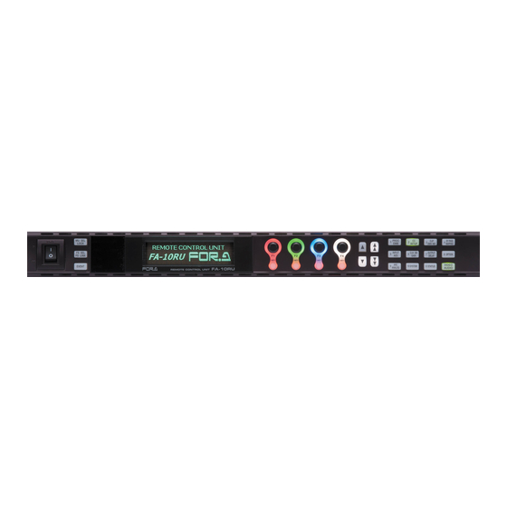
- Page 6 BY-PASS GENLOCK FAN ALARM MU /FS SETUP DWN MIX MAPPING FREEZE DC POWER DISPLAY AREA INPUT CLN SW OUTPUT OPTION GAINI DELAY VIDEO TEST SIGNAL UNITY UNITY UNITY UNITY VIDEO BY-PASS SYSTEM STATUS ANALOG AUDIO FA-10RU REMOTE CONTROL UNIT AUDIO...
-
Page 7: Table Of Contents
Table of Contents 1. Prior to Starting ...........................10 1-1. Overview ...........................10 1-2. Features ............................10 1-3. About This Manual ........................10 2. Panel Descriptions ..........................11 2-1. Front Panel ..........................11 2-2. Rear Panel ..........................12 2-3. Internal Settings ........................13 2-3-1. Dipswitch Settings ......................13 3. Connection ............................14 3-1. - Page 8 5-24. NOISE REDUCER ........................40 5-25. UHD UPCONVERSION (FS1) ....................40 5-26. GPI UTILITY ..........................41 5-27. SLOT B / SLOT C GPI FUNCTION ..................41 5-28. SLOT E GPI FUNCTION......................43 5-29. ANCILLARY MULTIPLEX .......................43 5-30. VIDEO PAYLOAD ID ......................44 5-31. TIME CODE MULTIPLEX .......................44 5-32.
- Page 9 10-1. FA GPIO Editor ........................92 10-1-1. Software Installation ......................92 10-1-2. Verifying GPIO Editor Version ..................94 10-1-3. Connecting FA GPIO Editor to the FA-10RU ..............95 10-1-4. Setting GPI Functions ......................96 10-1-5. Exporting / Importing GPI Settings ..................97 10-2. GPI Input Patterns ........................98 10-3.
-
Page 10: Prior To Starting
1. Prior to Starting 1-1. Overview The FA-10RU is a remote control unit that allows you to control FA-505, FA-1010 and FA-9600 Frame Synchronizer units via network. (This manual explains the FA-9600 operations from FA-10RU units. Refer to “FA-10RU for FA-9600 Operation Manual” for the FA-9600 operations.) 1-2. -
Page 11: Panel Descriptions
Holding down the button locks front panel buttons. Lit orange LOCK when LOCK is on. button To release LOCK, hold down the button again. Used to switch menu button (9) functions after the FA-10RU is FS SEL connected to an FA-9600. FS LINK 4-3-8 Unlit: Selects menu items. -
Page 12: Rear Panel
Name Description Ref. Lit red A power failure has occurred. 5-53 Flashing red Power Off the unit and consult your Status POWER (*1) FOR-A reseller. indicator (*2) Unlit Power supply is normal. Menu display Used to display menus and make operational settings. Used to change operational settings. -
Page 13: Internal Settings
2-3. Internal Settings IMPORTANT Note that internal switch settings should not be changed from factory defaults. If you have accidentally changed the settings, return them to the factory default settings as shown in this section. Be sure to have qualified technical personnel perform the settings and adjustments in the interior, or contact your dealer. -
Page 14: Connection
Specify unique IP addresses for all devices connected to the network. See Sec. 9-2. Network Settings for details on setting IP addresses. One FA-9600 unit can be controlled by up to 5 units of FA-10RU and/or FA-DCCRU maximum. An attempted 6... -
Page 15: Connection With Option/Expansion Units
TO MU (10/100/1000BASE-T) See Sec. 10. “GPI Interface” for details on GPI connectors. 3-3. System Requirements (Web-based Control) To utilize the FA-10RU from a web browser, your computer must meet the following requirements. Windows® 7 /8.1 Windows® 10 Professional (32/64bit) Professional (32/64bit) Intel®... -
Page 16: Front Panel Operations
4-2-1. Connecting in Unit ID Selection Mode To connect to an FA-9600 in Unit ID Selection Mode, the unit must be registered in the FA-10RU. See Sec. 9-4. “Unit ID Assignment” for details on how to register FA-9600 units. ... -
Page 17: Connecting In Ip Address Selection Mode
If Remote Unit of the Remote Control Unit Setting menu is set to Refuse in the FA-9600, FA-10RU cannot control the FA-9600 remotely and shows a message “* MU refuses FA-10RU commands” at the bottom of the CONNECT STATE menu. -
Page 18: Basic Operations
4-3. Basic Operations This section explains how to select menus and set parameters. Most of the menus can be controlled by these basic operations. However, some menus work differently. See the descriptions given for each menu for details. IMPORTANT Make sure that the LOCK indicator on the front panel is turned off before starting an operation. If the LOCK indicator is lit orange, all operations on the front panel except the LOCK button are disabled. -
Page 19: Arrow Buttons
4-3-2. Arrow Buttons Double-arrow buttons (up and down) The double-arrow buttons allow you to move between menus. Single-arrow buttons (up and down) The single-arrow buttons allow you to move between items in the menu. The single-arrow button light goes off when it reaches the last item in the direction. - - - V I D E O P R O C E S S A M P L I F I E R - - - P 3 0 0 F 1 F S S E L : F S 1... -
Page 20: Menu List
4-3-5. Menu List Menu Buttons PROC CLIP BY-PASS SETUP DWN MIX MAPPING INPUT CLN SW OUTPUT OPTION GA IN DELAY VIDEO STA TUS SYSTEM ANA LOG AUDIO - - - V I D E O P R O C E S S A M P L I F I E R - - - P 3 0 0 F 1 F S S E L : F S 1 P R O C E S S : P r e p r o c e s s... - Page 21 AES AUDIO INPUT HYSTERESIS OP(AES) AUDIO HYSTERESIS *6 5 INPUT INPUT SELECT(Sync) AES TERMINAL IN/OUT SET INPUT SELECT(Proc)/LINKAGE OP(AES) TERMINAL IN/OUT SET *6 AES INPUT POLARITY OP(AES) INPUT POLARITY *6 EMBEDDED AUDIO OUTPUT GAIN 6 CLN SW Not functioning AES AUDIO OUTPUT GAIN GAIN OP(AES) AUDIO OUTPUT GAIN *6 AUDIO INPUT DELAY(Ch.1-16)
-
Page 22: Changing Setting Values
OPTION SLOT C INFORMATION OPTION SLOT D/E, PS INFORMATION SOFTWARE OPTION INFORMATION MU OPERATION INFORMATION VIDEO Video menus are activated when the Audio menus are activated when the button AUDIO button lights green. lights orange. *1 FA-96AHDR/96AHDR2 software required. *2 FA-96EX3G44-R (in Slot A) required *3 FA-96UDC software required *4 FA-10GPI required *5 FA-96DB9-CBL (in Slot E) required. -
Page 23: Resetting To Default
4-3-7. Resetting to Default The UNITY indicator light goes off when the setting value is changed from the default value. Pressing the UNITY button while the light is off returns the corresponding setting value to the default value. Then the light turns on. Pressing the button again returns the value to the previous value before resetting to the default value. -
Page 24: Video Menus
5. VIDEO Menus Make the menu buttons light up green using the VIDEO/AUDIO button. (Pressing the button while the buttons are lit orange turns the lights green.) Then the menus displayed on the upper row on each menu button can be selected. 5-1. -
Page 25: Gamma/Color
5-2. GAMMA/COLOR - - - G A M M A / C O L O R - - - P 3 0 3 Simultaneous 4K/HD F 1 F S S E L : F S 1 Dual HD D y n a m i c R a n g e C o n v . : B y p a s s 3D-LUT (FS1) G a m m a C u r v e ( E O T F ) : S D R 2 . -
Page 26: In/Out Gamma/Color
5-3. IN/OUT GAMMA/COLOR - - - I N / O U T G A M M A / C O L O R - - - P 3 0 3 Simultaneous 4K/HD F S S E L : F S 1 Dual HD F 1 C o n v e r s i o n : B y p a s s... -
Page 27: Sr-Live
(INPUT SIDE) Setting range Parameter Default Description (Steps) FS SEL Selects an FS. Disable OOTF for HLG Disable Enables/disables OOTF for HLG. Enable Setting Enable converts the gamma curve of signals from HLG (Hybrid Log-Gamma) Disable OOTF Disable to another in consideration of OOTF Enable (Opt-Optical Transfer Function, BT.2100) conversions. -
Page 28: Area Maker
5-6. AREA MAKER This menu requires FA-96AHDR/96AHDR2 optional software. - - - A R E A M A K E R - - - P 3 1 3 Simultaneous 4K/HD F 1 F S S E L : F S 1 Dual HD M a k e r : D i s a b l e 3D-LUT... -
Page 29: Color Correction (Balance)
5-8. COLOR CORRECTION (BALANCE) - - - C O L O R C O R R E C T I O N ( B A L A N C E ) - - - P 3 1 4 Simultaneous 4K/HD F 2 C t l S e l :... -
Page 30: Knee (Rgb Clip) White/Black
5-10. KNEE (RGB CLIP) White/Black - - - K N E E ( R G B C L I P ) W h i t e - - - P 3 1 9 Simultaneous 4K/HD F 1 F S S E L : F S 1 F 2 S p l i t : O p e r a t e Dual HD C l i p... -
Page 31: Ycbcr Clip
5-11. YCbCr CLIP - - - Y C b C r C L I P - - - P 3 2 2 Simultaneous 4K/HD F 1 F S S E L : F S 1 Dual HD C l i p : D i s a b l e S p l i t : O p e r a t e 3D-LUT (FS1) -
Page 32: Input Select (Sync)
5-13. INPUT SELECT (Sync) - - - I N P U T S E L E C T ( S y n c ) - - - P 3 2 6 Simultaneous 4K/HD F 1 F S S E L : F S 1 Dual HD S o u r c e S e l e c t : I N 1... -
Page 33: Input Select(Proc) / Linkage
5-14. INPUT SELECT(Proc) / LINKAGE - - - I N P U T S E L E C T ( P r o c ) - - - P 3 2 7 Simultaneous 4K/HD F 1 F S S E L : F S 1 Dual HD S o u r c e S e l e c t : S y n c h r o n i z e r 1... -
Page 34: Output Select (Slot A)
5-16. OUTPUT SELECT (Slot A) This menu is enabled if FA-96EX3G44-R is installed into Slot A. If FA-96EX3G44-R is installed: - - - O U T P U T S E L E C T ( S l o t A ) - - - P 3 2 9 Simultaneous 4K/HD... -
Page 35: Format Converter
5-17. FORMAT CONVERTER This menu specifies the format after conversion and requires FA-96UDC software. - - - F O R M A T C O N V E R T - - - P 3 3 2 Simultaneous 4K/HD F 1 F S S E L : F S 1 C o n v e r t e r : F o l l o w I n p u t Dual HD F o r m a t S t a n d a r d : 1 0 8 0... -
Page 36: Converter Delay
5-18. CONVERTER DELAY This menu requires FA-96UDC software. - - - C O N V E R T E R D E L A Y - - - P 3 3 3 Simultaneous 4K/HD F 1 F S S E L : F S 1 Dual HD D e l a y M o d e : F r a m e 3D-LUT (FS1) -
Page 37: Resize
5-19. RESIZE This menu requires FA-96UDC software. - - - R E S I Z E - - - P 3 3 7 Simultaneous 4K/HD (FS1) F S S E L : F S 1 S c a l i n g : D i s a b l e Dual HD S D O u t p u t A s p e c t : 4 : 3 L 1 6 : 9 T 3D-LUT (FS1) -
Page 38: Improvement In Converter
5-20. IMPROVEMENT IN CONVERTER This menu requires FA-96UDC software. - - - I M P R O V E M E N T I N C O N V E R T E R - - - P 3 3 9 Simultaneous 4K/HD F 1 F S S E L : F S 1 Dual HD... -
Page 39: Antialias H/V
5-22. ANTIALIAS H/V This menu requires FA-96UDC software. - - - A N T I A L I A S H / V - - - P 3 4 1 Simultaneous 4K/HD (FS1) F 1 F S S E L : F S 1 Dual HD H o r i z o n t a l 3D-LUT (FS1) -
Page 40: Noise Reducer
5-24. NOISE REDUCER This menu requires FA-96UDC software, and is disabled if Converter is set to Follow Input in the FORMAT CONVERTER menu. - - - N O I S E R E D U C E R - - - P 3 4 4 Simultaneous 4K/HD (FS1) F 1 F S S E L : F S 1... -
Page 41: Gpi Utility
5-26. GPI UTILITY FA-96GPI or FA-96DB9-CBL option is required to be installed on the FA-9600 Slot B and/or C. - - - G P I U T I L I T Y - - - P 3 5 3 Simultaneous 4K/HD F 1 G P I L o c k : U n l o c k e d Dual HD... - Page 42 <GPI Input Setting Example 2> Port No.: 2 In Level 1: Event Load In Level 2: Default Default settings are loaded to FA-9600 whenever Port 2 receives a GPI pulse. Parameter Default Setting range Description None Unit Alarm Out Level 1 None Video In Audio In Event Tally...
-
Page 43: Slot E Gpi Function
5-28. SLOT E GPI FUNCTION FA-96DB9-CBL option is required to be installed on the FA-9600 Slot E. - - - S L O T E G P I F U N C T I O N - - - P 3 5 6 Simultaneous 4K/HD F 1 P o r t : P o r t 1... -
Page 44: Video Payload Id
5-30. VIDEO PAYLOAD ID - - - V I D E O P L A Y L O A D I D - - - P 3 5 9 Simultaneous 4K/HD F 1 F S S E L : F S 1 Dual HD P a y l o a d I D : P a s s... -
Page 45: Tcg1-1 (Ltc), Tcg2-1 (Ltc)
5-32. TCG1-1 (LTC), TCG2-1 (LTC) To insert a timecode into SDI output using this menu, set H ANC to Overwrite. (See Sec. 5-29. “ANCILLARY MULTIPLEX.”) - - - T C G 1 - 1 ( L T C ) - - - P 3 6 1 Simultaneous 4K/HD F 1 F S S E L : F S 1... -
Page 46: Tcg Control (Color Processor1/2)
5-34. TCG CONTROL (Color Processor1/2) This menu allows you to generate timecodes. Use the timecodes when Source is set to Generator for timecode settings (TCG1-1(LTC), TCG2-1(LTC), TCG2-1 (VITC/DVITC) or TCG2-2 (VITC/DVITC)) in the menu (P361 or 362). - - - T C G C O N T R O L ( C o l o r P r o c e s s o r 1 ) - - - P 3 6 3 Simultaneous 4K/HD F 1 A p p l y : T S G 1 - 1 ( L T C ) -
Page 47: Anc Data Embedded
5-36. ANC DATA EMBEDDED This menu allows you to determine whether to pass through the following two VANC data packets inserted in SDI input. ARIB STD-B37 (Closed Caption Data) ARIB STD-B39 (Inter-Stationary Control Data) Other VANC data packets cannot be managed independently, To enable this menu, set V ANC to Rewrite. -
Page 48: Synchronized Format
5-38. SYNCHRONIZED FORMAT Select each FS output video format. - - - S Y N C H R O N I Z E D F O R M A T - - - P 3 7 0 Simultaneous 4K/HD F 1 F S S E L : F S 1 F m t S e t t i n g : A u t o D e t e c t Dual HD F o r m a t S t a n d a r d : 1 0 8 0... -
Page 49: Video Freeze
Parameter Default Setting range Description Selects the reference mode. Use “Frame” if genlock input and video input signals are not synchronized. When adjusting video signals, the reference point (H:0, V:0) can be offset under Timing settings. If the reference point is changed, adjustable ranges are also changed accordingly. -
Page 50: Video Input Status
5-42. VIDEO INPUT STATUS - - - V I D E O I N P U T S T A T U S - - - P 3 7 9 Simultaneous 4K/HD I N 1 : 1 9 2 0 x 1 0 8 0 5 9 . 9 4 i Dual HD I N 2 : 1 9 2 0 x 1 0 8 0 5 9 . -
Page 51: Video Process Status
5-44. VIDEO PROCESS STATUS - - - V I D E O I N P U T S T A T U S - - - P 3 8 2 Simultaneous 4K/HD V I D E O F O R M A T Dual HD F S 1 O U T : 1 9 2 0 x 1 0 8 0 5 9 . -
Page 52: Input Payload Id (Slot A)
Item Input signal format Description SD/HD Displays no data. Link A 3G Level A Displays the payload ID information on Y signal. 3G Level B Displays the payload ID information inserted on Link A. SD/HD Displays no data. Link B 3G Level A Displays the payload ID information on C signal. -
Page 53: Input Ancillary Detection 1-3
5-49. INPUT ANCILLARY DETECTION 1-3 Displays the ancillary data status in the SDI input. - - - I N P U T A N C I L L A R Y D E T E C T I O N 1 - - - P 3 8 8 Simultaneous 4K/HD F S 1 F S S E L : F S 1... -
Page 54: Main Unit Status / Information / Version
5-53. MAIN UNIT STATUS / INFORMATION / VERSION - - - M A I N U N I T S T A T U S - - - P 3 9 8 Simultaneous 4K/HD F A N 1 : N o r m a l Dual HD F A N 2 : N o r m a l... -
Page 55: Option Slot A-D/E Information
5-54. OPTION SLOT A-D/E INFORMATION Displays the FA-9600 option information such as installed optional cards and software. - - - O P T I O N S L O T A I N F O R M A T I O N - - - P 4 0 1 Simultaneous 4K/HD M o d e l : F A - 9 6 E X 3 G 4 4 - R... -
Page 56: Audio Menus
6. AUDIO Menus Make the menu buttons light up orange using the VIDEO/AUDIO button. (Pressing the button while the buttons are lit green turns the lights orange.) Afterwards, the audio menus displayed on the lower row on each menu button can be selected. 6-1. -
Page 57: Audio Mux. Mode (Arib Std-B39)
Auto Selects an audio clock to be used when Group1 Reference Auto embedding audio into SDI output. Input CH 1/2 Clock Auto: Automatically selects as shown below. Input CH 3/4 A clock in a channel pair if the pair is non-PCM. Auto A clock in the younger channel pair if two Group2... -
Page 58: Embedded Audio In Polarity
6-4. EMBEDDED AUDIO IN POLARITY - - - E M B E D D E D A U D I O P O L A R I T Y - - - P 4 1 5 Simultaneous 4K/HD F 1 F S S E L : F S 1 Dual HD 3D-LUT (FS1 / EMB1) 1 : N O R M... -
Page 59: Sampling Rate Converter (Src)
6-6. SAMPLING RATE CONVERTER (SRC) - - - S A M P L I N G R A T E C O N V . ( C h . 1 - 1 6 ) - - - P 4 2 0 Simultaneous 4K/HD F 1 C H 1 / 2 : A u t o F 2 C H 3 / 4 : A u t o... -
Page 60: Audio Down Mix1-2
6-8. AUDIO DOWN MIX1-2 Selects an operational mode and audio sources for 2 Downmix circuits Downmix 1 should be set in P432 and P433. Downmix 2 should be set in P434 and P435. The menu configuration is the same for both of them. - - - A U D I O D O W N M I X 1 ( L e v e l ) - - - P 4 3 2 Simultaneous 4K/HD... -
Page 61: Emb. Audio Output Mapping
6-9. EMB. AUDIO OUTPUT MAPPING - - - E M B . A U D I O O U T P U T M A P P I N G 1 / 2 - - - P 4 3 8 Simultaneous 4K/HD F 1 F S S E L : F S 1 Dual HD... -
Page 62: Hdmi Audio Output Select
6-11. HDMI AUDIO OUTPUT SELECT Selects 8 source channels for the HDMI audio output from all audio channels embedded in Proc.1(FS1) or Proc.2(FS2) that is selected as the HDMI output source. - - - H D M I A U D I O O U T P U T S E L E C T - - - P 4 4 5 Simultaneous 4K/HD F 1 O u t p u t E n a b l e... -
Page 63: Aes Terminal In/Out Set
6-13. AES TERMINAL IN/OUT SET Note that this menu is NOT displayed if FA-96AES-UBLC is installed on FA-9600, because all AES ports are automatically set to input. - - - A E S T E R M I N A L I N / O U T S E T - - - P 4 5 2 Simultaneous 4K/HD F 1 C H 1 / 2 - C H 3 / 4 : I n p u t... -
Page 64: Aes Audio Output Gain
Parameter Default Setting range Description FS SEL Selects an FS. -20.0 to +20.0 dB Sets the output gain for each embedded CH1-16 0.0dB (0.1 dB) audio channel. -20.0 to +20.0 dB Sets the output gain offset for all Master Gain 0.0dB (0.1 dB) embedded audio channels. -
Page 65: Dolby E Alignment
Parameter Default Setting range Description CH1-CH16 Sets the audio delay for each audio 1ms -1000ms source channel. CH17-CH32 Sets the audio delay for all 16 audio Master 1ms -1000ms source channels per page. Video Delay Displays video delay (excluding the video converter delay) for FS1 or FS2 When selecting Master using single arrow buttons, “Push F3 UNITY, adjust to video delay”... -
Page 66: Audio Output Conv Delay
6-19. AUDIO OUTPUT CONV DELAY This menu requires FA-96UDC software. - - - A U D I O O U T P U T C O N V D E L A Y - - - P 4 7 1 Simultaneous 4K/HD F 1 E M B . -
Page 67: Audio Mute/Test Signal
Preamble Z appearance and EDP (Extended Data Packet, SD-SDI), in (*2) addition to above. Selects an action to be performed when an input audio error is detected. Disable: Continues to pass through Enable audio without using fade or mute effect. Error Fade Disable Disable... -
Page 68: Embedded1-2 Audio Input Status
6-22. EMBEDDED1-2 AUDIO INPUT STATUS Displays the embedded audio input status. - - - E M B E D D E 1 A U D I O I N P U T S T A T U S - - - P 4 8 0 Simultaneous 4K/HD Dual HD... -
Page 69: Emb.audio Clock Error
6-24. EMB.AUDIO CLOCK ERROR Displays the number of warnings and errors for each audio group. To reset counts, press F1 Unity or F2 Unity. Wxxxx: Warnings are counted up when timing errors are corrected. Exxx: Errors are counted up when timing errors cannot be corrected. - - - E M B . -
Page 70: Hdmi Audio Output Status
6-27. HDMI AUDIO OUTPUT STATUS Displays the HDMI audio output status. Refer to Sec. 6-22. “EMBEDDED 1-2 AUDIO INPUT STATUS” for details on states. - - - H D M I A U D I O O U T P U T S T A T U S - - - P 4 9 1 Simultaneous 4K/HD C H 1 : L o s s... -
Page 71: Event Memory
7. Event Memory The FA-10RU can store and recall 100 event memories. It can also control 100 event memories in the connected FA-9600. FA-9600, FA-1010 and FA-505 settings are stored in different memory banks. Therefore, other FA main unit settings cannot be loaded to FA-9600 units. -
Page 72: Fa-10Ru System Menu
8. FA-10RU SYSTEM Menu Pressing the MU SELECT button, then the 10 SYSTEM button (lit red), opens a menu, allowing you to verify the FA-10RU GPI function assignments, front panel display settings, and software versions. 8-1. LOAD GPI INPUT PATTERN Allows you to assign functions to GPI 10 inputs / outputs simultaneously using patterns. -
Page 73: Gpi Input Port Function
8-2. GPI INPUT PORT FUNCTION Allows you to assign functions to GPI input pins individually. - - - G P I I N P U T P O R T F U N C T I O N - - - P 8 2 2 F 1 P o r t : G P I 1 P O R T 1 ( F A - A U X 3 0 L e f t B l o c k ) MU SEL... - Page 74 All Audio Test GPI Lock On, Off, On/Off Event Menu, Default, Memory Load FA-10RU, MU Salvo No1-100 Event Memory Save Menu, No1-100 FA-10RU, MU Salvo None, FS1, FS2 None, Menu Move P000-P1499 FS3-FS10 Line1-Line8 None, FS1, FS2 Color Corrector Split Off, Mode1-3...
- Page 75 If Menu is selected under Setting 2, the MU Select page opens instead of establishing a new connection. If Disconnect is selected under Setting 2, the FA-10RU is disconnected from the main unit. See Sec. 4-2-1. “Connecting in Unit ID Selection Mode” for details on IDs.
- Page 76 FS will remain unchanged, and only the menu display will be changed. See Sec. 5-7. “COLOR CORRECTION (BALANCE).” Ineffective if FA-9600 is in 3D-LUT mode. Freeze Setting1 Setting2 Setting3 Setting4 Menu Frame None None Freeze (Mode) FS1-FS10 Menu Even None None Freeze (On/Off)
- Page 77 Audio Gain (AES) Setting1 Setting2 Setting3 Setting4 Menu Audio Gain (AES) Option Slot A-D * Selecting Audio Gain(AES) under Setting 1 opens the Audio Gain(AES) menu when the circuit is closed. To switch Options, select an Option under Setting 2. Ineffective if no AES Option is installed.
- Page 78 Video Test Signal Setting1 Setting2 Setting3 Setting4 Menu None Video Test Signal (Off) Menu Video Test Video Test Signal (100% CB) Signal Video Test Signal (75% CB) FS1-FS10 On/Off Video Test Signal (SMPTE CB) On (with Menu Move) On/Off (with Menu Move) Video Test Signal (RAMP) Selecting Video Test Signal under Setting 1 allows a video test signal, selected under Setting 2, to be output when the circuit is closed.
- Page 79 Memory Load Setting1 Setting2 Setting3 Setting4 Menu Event FA-10RU Memory Load Default Salvo * No1-100 Selecting Memory Load allows you to load the memory data selected under Setting 2, 3 and 4. See Sec. 7-1. “LOAD EVENT MEMORY” for details.
- Page 80 Color Correction Split Setting1 Setting2 Setting3 Setting4 None None Color Correction Split Off,Mode1, Mode2, Mode3 FS1-FS10 Menu Selecting Color Correction Split under Setting 1 allows you to display the menu selected under Setting 2, 3, and 4 when the circuit is closed. Setting 2 allows you to specify the Color Correction Split mode.
- Page 81 Input Gamma (EOTF) Setting1 Setting2 Setting3 Setting4 Bypass None None Input Gamma (EOTF) FS1-FS5 Menu Pattern1-13 Selecting Input Gamma (EOTF) under Setting 1 allows you to display the menu selected under Setting 2, 3, and 4 when the circuit is closed. This setting selects a 3D-LUT table if FA-9600 is in 3D-LUT mode.
-
Page 82: Gpi Output Port Function
Right Block) GPI3 Port21-30 (FA-AUX30 Right Block) None Follow GPI In Setting All DC/FAN Alarm FA-10RU FAN Alarm Selects a function to be MU/FA-10RU FAN Alarm assigned to the pin. MU FAN1-4 Alarm See Sec. 8-2-3. “GPI Setting None DC Power Alarm OUTPUT Functions”... -
Page 83: Gpi Output Functions
All DC/FAN Alarm *1 power, or FA-10RU FAN unit. FA-10RU FAN Alarm Outputs a signal if an alarm is detected in the FA-10RU FAN unit. Outputs a signal if an alarm is detected in an FA-9600 or FA-10RU MU/FA-10RU FAN Alarm *1 FAN unit. -
Page 84: Front Panel Set
30 min Sets brightness for front panel LEDs. LED Brightness Level4 Level 1 - 8 Level 1 – 8: Dark - Bright Disable Disable: Disables the FA-10RU buzzer. FA-10RU Enable Buzzer Enable Enable: Enables the FA-10RU buzzer. Disable Disable: Disables the GPI buzzer. -
Page 85: Fa-10Ru Information
8-6. FA-10RU INFORMATION Displays the FA-10RU version information and FA-10RU FAN unit status. - - - F A - 1 0 R U I N F O R M A T I O N - - - P 8 3 3 F P G A 1 V e r s i o n : 1 . -
Page 86: Web Browser Settings
Click on a page link such as Network Settings, User Account Settings shown on the left side of the screen, the following “Windows Security” dialog will appear. Enter your user name and password. User name: fa10ru User password: foranetwork Then click OK. After successful authentication, you will have access to all the FA-10RU pages. -
Page 87: Information
Click Information. The information page as shown below appears. Unit Information Item Description Serial Number Displays the serial number of the FA-10RU. FPGA1 Version Displays the version of the FA-10RU FPGA1. FPGA2 Version Displays the version of the FA-10RU FPGA2. Soft Version Displays the version of the FA-10RU Software. -
Page 88: Network Settings
9-2. Network Settings Clicking Network Settings opens the dialog box as shown below. To change the network address, change the settings and click Submit. Changes will be applied after reboot or restart (see Sec. 9-7) is performed. 9-3. User Account Settings Clicking User Account opens the dialog box as shown below. -
Page 89: Unit Id Assignment
Clicking Event Naming (FA-9600) opens the dialog box as shown below. Setting Procedure This page allows you to rename evens (Event1 to Event100) saved in the FA-10RU. (1) Enter a desired name (up to 15 alphanumeric characters) in the Event Name field. -
Page 90: Backup & Restore
9-6. Backup & Restore Clicking Backup & Restore opens the dialog box as shown below. This dialog box allows you to save the FA-10RU settings and event data to a PC. The saved data can be recalled. 9-6-1. Configuration Data Backup The FA-10RU configuration data can be saved/recalled to/from a PC as a CSV file. -
Page 91: Event Data Backup
Be sure to perform restart as described in section 9-7. “Restart.” 9-6-2. Event Data Backup All event data for FA-9600 saved in the FA-10RU can be saved/recalled to/from a file on a PC Saving all Event Data to a file on a PC (1) Click Save File: Save under “Backup Event Data (FA-9600).”... -
Page 92: Gpi Interface
10. GPI Interface The GPI1, GPI2 and GPI3 connectors provide a total of 30 inputs and 30 outputs. Functions can be assigned to each terminal as well as a group of terminals using patterns, which are set for specific purposes (Pattern Load). Refer to Secs. 8-1 to 8-2 for details on function assignments. The FA GPIO Editor also allows you to set GPI assignments on the GUI screen (see the following chapters). - Page 93 (4) The installation directory of the FA GPIO Editor is displayed. To change the default installation directory, click Change… and specify a new directory. (5) Click Next. (6) The last wizard page is displayed. Verify the installation settings and click Install to install the software.
-
Page 94: Verifying Gpio Editor Version
(7) When the software installation is complete, the window as shown below will appear. Click Finish to finish the installation. 10-1-2. Verifying GPIO Editor Version Click Version Information in the menu bar. A window as shown below will appear. To close the window, click OK. -
Page 95: Connecting Fa Gpio Editor To The Fa-10Ru
(3) When the user name and password are accepted, a window as shown below is displayed and FA-10RU GPI settings are loaded in the window. When the user name and password are not accepted, an error pop-up dialog windows appears. -
Page 96: Setting Gpi Functions
GPI inputs/outputs are quickly set. Loaded settings (including output functions) can be changed. (See "If Setting Individually" below.) (3) After all GPI settings are finished, click Apply to send the settings to the FA-10RU unit. If a “Successful settings” message appears, GPI settings are complete. -
Page 97: Exporting / Importing Gpi Settings
GPI settings can be loaded from files in the computer. (1) Select File > Import in the menu bar. (2) Specify the file name (such as FA-10RU GPIO.csv) and location. (3) Verify settings in the FA GPIO Editor, then click Apply... -
Page 98: Gpi Input Patterns
10-2. GPI Input Patterns This section describes GPI Input setting patterns that can be selected in the LOAD GPI PATTERN menu (section 8-1). The following figures depict FA-AUX30 buttons. GPI1-3 BLOCK Button Button name Description setting Each button establishes a connection to the Main Unit MU Select 1-10 MU ID1-10... - Page 99 GPI1-3 BLOCK setting Button Button name Description (*2) Freeze (FS1-FS10) FREEZE FS1-2 Turns the FREEZE FS1-2 function On/Off. Audio Gain (FS1-FS10) Opens the EMBEDDED AUDIO OUTPUT GAIN FS1-2 (*2) GAIN menu and lights the button. These buttons are disabled with default settings when connecting to FA-9600 units.
- Page 100 Menu 3 Select Opens the SAVE EVENT MEMORY menu and lights the EVENT SAVE button. The button LED lights if an alarm is detected in a FAN or power unit of the connected FA-9600, or a FAN unit in the ALARM FA-10RU.
- Page 101 The corresponding button LED lights if an alarm occurs in FAN1-4 FAN1-FAN3 in the connected FA-9600. FAN4 is ineffective. The button LED lights if an alarm occurs in an FA-10RU FAN unit. RU FAN Pressing the button opens the FA-10RU INFORMATION Status 2 menu.
-
Page 102: Gpi 1-Gp I3 Pin Assignments
10-3. GPI 1-GP I3 Pin Assignments GPI connector 25-pin D-sub, female Signals Pin No. GPI1 GPI2 GPI3 GND (Ground) GPI OUT 1 (Output) GPI OUT 11 (Output) GPI OUT 21 (Output) GPI OUT 2 (Output) GPI OUT 12 (Output) GPI OUT 22 (Output) GPI OUT 3 (Output) GPI OUT 13 (Output) - Page 103 Pulse signals The pulse signal level change (OPEN to CLOSE) triggers each operation. OPEN to CLOSE: The assigned function will be turned on. 100msec or more OPEN CLOSE GPI Output Circuit (Same for GPI 1-3) Select external or internal FA-9600 inside power.
-
Page 104: Command Control
11. Command Control FA-10RU units can accepts the MU Select command over LAN. 11-1. Communication Method Communication Interface Ethernet: IEEE802.3u/ab method (100BASE-TX / 1000BASE-T) Protocol TCP/IP, UDP/IP Port number 60000 (Fixed) Connection timeout 30 seconds (See Error Code 99.) Maximum connection number Control command Sends to FA-10RU. -
Page 105: Connection Status Request Command (Status)
FS1, FS2, or --- (Disconnected) Connecting Connection refused Connected Send ACK[CR][LF] when you receive a connection status message. If FA-10RU receives no ACK, it re-sends the status message three times at one-second intervals. Error Response Return message (TCP): ERR<Error code>[CR][LF]] Any of the following error messages is returned if a command is not properly received. -
Page 106: Specifications And Dimensions
POWER SETUP DWN MIX MAPPING LOCK FREEZE DC POWER DISPLAY AREA FS SEL INPUT CLN SW OUTPUT OPTION FS LINK GAINI DELAY TEST SIGNAL UNITY UNITY UNITY UNITY VIDEO EVENT BY-PASS SYSTEM STATUS ANALOG AUDIO FA-10RU REMOTE CONTROL UNIT 12.7... - Page 107 Warning This equipment has been tested and found to comply with the limits for a Class A digital device, pursuant to Part 15 of FCC Rules. These limits are designed to provide reasonable protection against harmful interference when the equipment is operated in a commercial environment. This equipment generates, uses, and can radiate radio frequency energy and, if not installed and used in accordance with the instruction manual, may cause harmful interference to radio communications.
- Page 108 June 14, 2019 Printed in Japan FOR-A COMPANY LIMITED Head Office 3-8-1 Ebisu, Shibuya-ku, Tokyo 150-0013, Japan Overseas Division Tel: +81(0)3 3446 3936 Fax: +81(0)3 3445 5116 Japan Branch Offices Osaka/Okinawa/Fukuoka/Hiroshima/Nagoya/Sendai/Sapporo R&D/Production Sakura Center/Sapporo Center FOR-A Corporation of America 11155 Knott Ave., Suite G&H, Cypress, CA 90630, USA. Tel: +1 714 894 3311 Fax: +1 714 894 5399 FOR-A Corporation of America East Coast Office...
Need help?
Do you have a question about the FA-10RU and is the answer not in the manual?
Questions and answers