
Related Manuals for FOR-A HVS-AUX16A


Summary of Contents for FOR-A HVS-AUX16A
- Page 1 OPERATION MANUAL HVS-AUX16A HVS-AUX16B HVS-AUX16C HVS-AUX16D HVS-AUX32A HVS-AUX64A Auxiliary Unit Edition - Rev. 1...
- Page 2 Edition Revision History Edit. Rev. Date Description Section/Page 2014/05/19 2014/06/06 Supported HVS-390HS 2015/04/14 Supported HVS-2000 Sec. 3-3 Changed model names (HVS-XT100/110 >> HVS-100/110) 2015/07/27 Added HVS-AUX16B. 2018/07/27 Supported HVS-490 and HVS-1200 2019/02/25 Added HVS-AUX16C/16D Supported HVS-2000/6000 2019/06/26 Supported HVS-490/1200...
- Page 3 Precautions Important Safety Warnings [Power] Operate unit only at the specified supply voltage. Caution Disconnect the power cord via the power plug only. Do not pull on the cable portion. Do not place or drop heavy or sharp-edged objects on the power cord. A damaged cord can cause fire or electrical shock hazards.
- Page 4 Unit should not be operated or stored with cover, panels, and / or casing removed. Operating the unit with circuitry exposed could result in electric shock / fire hazards or a unit malfunction. Hazard [Potential Hazards] If abnormal odors or noises are noticed coming from the unit, immediately turn the power off and disconnect the power cord to avoid potentially hazardous conditions.
- Page 5 Upon Receipt HVS-AUX16A, HVS-AUX16B, HVS-AUX16C, HVS-AUX16D, HVS-AUX32A and HVS-AUX64A units and their accessories are fully inspected and adjusted prior to shipment. Operation can be performed immediately upon completing all required connections and operational settings. Check your received items against the packing lists below. Check to ensure no damage has occurred during shipment.
- Page 6 DC Cord Clamp Installation (HVS-AUX16A/32A/64A) Insert the DC cord into the DC IN connector, then secure the cord with the DC cord clamp attached to the hole as shown in the figure. DC12V IN...
-
Page 7: Table Of Contents
6. LCD Indicators (HVS-AUX16C/16D) ....................19 6-1. Switching Pages ........................19 6-2. FMT Setting ..........................19 7. Specifications and Dimensions ......................20 7-1. Unit Specifications ........................20 7-2. External Dimensions .........................21 7-2-1. HVS-AUX16A........................21 7-2-2. HVS-AUX16B........................21 7-2-3. HVS-AUX16C ........................22 7-2-4. HVS-AUX16D ........................22 7-2-5. HVS-AUX32A........................23 7-2-6. HVS-AUX64A........................23 Appendix 1. -
Page 8: Prior To Starting
Hereafter, “Switchers” in this document includes “Multiviewers.” HVS-AUX16C/16D does not support Multiviewers. 1-2. Features All buttons are user assignable: HVS-AUX16A and HVS-AUX16B - 16 buttons HVS-AUX32A - 32 buttons HVS-AUX64A - 64 buttons HVS-AUX16C and HVS-AUX16D - 16 buttons and 4-page switching by rotary encoder allows total of virtual 64 buttons. -
Page 9: Panel Descriptions
2. Panel Descriptions 2-1. Front Panel HVS-AUX16A HVS-AUX16A AUXILIARY UNIT LOCK POWER NET MASK AUX IP SW IP AUX ID OCTET BUSY SETUP SHIFT/TAKE LOCK RESET HVS-AUX16B HVS-AUX16B AUXILIARY UNIT POWER AUX IP NET MASK SW IP AUX ID... - Page 10 Do not power OFF the unit while BUSY LED is lit orange. Changing Button Labels Button labels can be changed for user-assignable buttons. Download and use the appropriate label template from the FOR-A Website product page. (See the back cover.)
-
Page 11: Rear Panel
2-2. Rear Panel HVS-AUX16A/32A/64A DC12V IN DC12V IN HVS-AUX16B/16D DC12V IN HVS-AUX16C DC12V IN SERVICE Letter Name Description For switcher connection Ethernet port (100BASE-TX, RJ-45) 12 V DC power inlet DC12V IN A redundant power supply is provided for HVS-AUX16C. -
Page 12: Connection
HVS-100 rear panel 75Ω terminator To AC power source To AC power source MU-OU connection cable POW ER DC 12V MOD E SW TO MU To AC adapter HVS-100OU rear panel To AC adapter DC12V IN HVS-AUX16A rear panel To AC adapter... -
Page 13: Connecting Hvs-390Hs
3-2. Connecting HVS-390HS HVS-AUX16A rear panel DC12V IN To AC adapter LAN cable (straight) TSG (Reference) Video Server HD/SD SDI VTR, etc. 75Ω termination HVS-390HS rear panel SDI INPUT GENLOCK REF IN REF OUT SDI OUTPUT HDMI GPI IN GPI/TALLY OUT... -
Page 14: Connecting Hvs-2000
SER. NO. AC100-240 V 50/60Hz IN POWER MONIT OR OUT LAN2 LAN1 HDMI (SUB) (MAIN) CONTROL GPI IN/T ALLY OUT MODE SW O FF RATING LABLE AC power source PC-based GUI menu HVS-AUX16A rear panel DC12V IN To AC power source... -
Page 15: Setup (Network Settings)
REF OUT TO OU GENLOCK SDI INPUT HDMI OUT RS-422 GPI IN/TALLY OUT AC100-240V 50/60Hz IN AC100-240V 50/60Hz IN HVS-AUX16A rear panel HVS-100 rear panel No network settings are required. Connect and use your AUX Unit under the factory default settings. -
Page 16: Connecting Two Or More Aux Units To A Switcher
4-3-1. Changing the AUX Unit IP Address HVS-AUX16A/16B/32A/64A The following setting procedure changes the IP address of HVS-AUX16A (2) in the above figure example, from 192.168.0.20 to 192.168.0.21. (1) Press SETUP. All indicators turn orange and indicate that the AUX Unit is in menu SETUP mode. -
Page 17: Changing The Aux Id Number
HVS-AUX16C/16D The setting procedure of HVS-AUX16C/16D is different from that of HVS-AUX16A. The procedure of HVS-AUX16C is explained here as an example. The following setting procedure changes the IP address of HVS-AUX16C from 192.168.0.20 to 192.168.0.21. (1) Press SETUP. All displays change to SETUP menu mode. -
Page 18: Lock And Inhibit
5. LOCK and INHIBIT LOCK and INHIBIT functions are used to prevent operation mistakes. LOCK function disables AUX unit operation and INHIBIT function disables selected buttons or rotary encoder. (INHIBIT function is available only on HVS-AUX16D) 5-1. LOCK (Front Panel Lock) The LOCK function allows you to disable AUX Unit front panel control. -
Page 19: Lcd Indicators (Hvs-Aux16C/16D)
6. LCD Indicators (HVS-AUX16C/16D) LCD button displays are installed on HVS-AUX16C and HVS-AUX16D. They can display assigned signal names, unit name, AUX ID, page no. and target switcher (See the table below.) See the Operation Manual of the destination unit for details on inputting display letters. Display How to display AUX ID... -
Page 20: Specifications And Dimensions
7. Specifications and Dimensions 7-1. Unit Specifications Free Buttons LOCK button Available Available Available Available Available Available SHIFT/TAKE Available Available TAKE only Available TAKE only TAKE only button INHIBIT button Available Available Rotary Encoder Available (PAGE switching) (4 PAGE) (4 PAGE) 100BASE-TX RJ-45 x 1 Interface (LAN) (For switcher connection. -
Page 21: External Dimensions
7-2. External Dimensions 7-2-1. HVS-AUX16A (All dimensions in mm.) HVS-AUX16A AUXILIARY UNIT LOCK POWER NET MASK AUX IP SW IP AUX ID OCTET BUSY SETUP SHIFT/TAKE LOCK RESET 7-2-2. HVS-AUX16B (All dimensions in mm.) HVS-AUX16B AUXILIARY UNIT POWER AUX IP... -
Page 22: Hvs-Aux16C
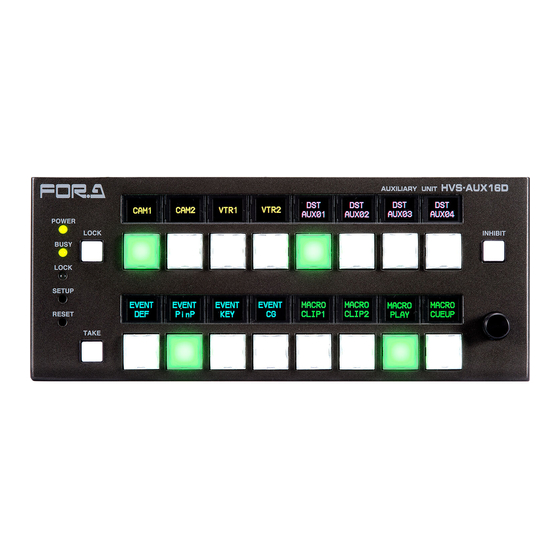
7-2-3. HVS-AUX16C (All dimensions in mm.) HVS-AUX16C AUXILIARY UNIT POWER BUSY SET UP LOCK RESET 7-2-4. HVS-AUX16D (All dimensions in mm.) HVS-AUX16D AUXILIARY UNIT POWER LOCK INHIBIT BUSY LOCK SET UP RESET TAKE... -
Page 23: Hvs-Aux32A
7-2-5. HVS-AUX32A (All dimensions in mm.) AUX IP NET MASK SW IP AUX ID OCTET HVS-AUX32A AUXILIARY UNIT LOCK POWER BUSY SETUP SHIFT/TAKE LOCK RESET 7-2-6. HVS-AUX64A (All dimensions in mm.) HVS-AUX64A AUXILIARY UNIT AUX IP NET MASK SW IP AUX ID OCTET POWER... -
Page 24: Appendix 1. Auto Line Feed
Appendix 1. Auto Line Feed The AUTO line feed function judges the breaking point of 6-14 character text automatically and displays 2 centered lines. (When total letter number is 5 or less, text is centered in a single line.) * The auto line feed is not applicable to a text with over 15 characters. - Page 25 (*1) Deciding the Line Breaking Point A breaking point is judged from the following conditions. If the text does not fit into the following conditions, automatic line feed is not applied. Text with multiple type characters (Ex. No. 1 and 5) Characters are classified into 3 types.
- Page 26 CAM01 Breaks a line after 5 letters. The punctuation mark is CAM01-SRC -SRC located at the beginning of the second line. a(12) a(12)bcd Breaks a line for not separating paired punctuation marks. Breaks a line in between alphabet and number. Source Source001 Small font is employed because letters in first line are 6.
- Page 27 Warning This equipment has been tested and found to comply with the limits for a Class A digital device, pursuant to Part 15 of FCC Rules. These limits are designed to provide reasonable protection against harmful interference when the equipment is operated in a commercial environment. This equipment generates, uses, and can radiate radio frequency energy and, if not installed and used in accordance with the instruction manual, may cause harmful interference to radio communications.
- Page 28 2 Executive Drive, Suite 670, Fort Lee Executive Park, Fort Lee, NJ 07024, USA Tel: +1 201 944 1120 Fax: +1 201 944 1132 FOR-A Corporation of America Distribution & Service Center 2400 N.E. Waldo Road, Gainesville, FL 32609, USA Tel: +1 352 371 1505...
Need help?
Do you have a question about the HVS-AUX16A and is the answer not in the manual?
Questions and answers