FOR-A FA-10RU Operation Manual
Remote control unit for fa-505
Hide thumbs
Also See for FA-10RU:
- Operation manual (124 pages) ,
- Quick setup manual (2 pages) ,
- Operation manuals (125 pages)

Subscribe to Our Youtube Channel
Related Manuals for FOR-A FA-10RU


Summary of Contents for FOR-A FA-10RU
- Page 1 OPERATION MANUAL FA-10RU for FA-505 Remote Control Unit Edition - Rev. 3 Software Version 8.44 or higher...
-
Page 2: Fpga1:
2019/04/12 Changed System Requirements. Added Command Control 2019/06/17 Added commands to external command control. Software Version and Supported Options Newly supported FA-10RU version Note Feature/Option FPGA1: 1.00 FA-505 (FA-505UD) Compatible FA-505 versions: FPGA2: 1.00 FA-50PS FPGA1-FPGA4: 1.00 or higher Software: 3.00... - Page 3 FA-9600 Version 3 support FPGA2: 1.00 External command control (MU SELECT command) Soft: 8.30 FPGA1: 1.00 FS selection support (MU Select command) FPGA2: 1.00 Status request command support Soft: 8.44 FA-10RU versions can be seen in the “FA-10RU INFORMATION” menu (see section 9-1-7).
- Page 4 Precautions Important Safety Warnings [Power] Operate unit only at the specified supply voltage. Caution Disconnect the power cord via the power plug only. Do not pull on the cable portion. Do not place or drop heavy or sharp-edged objects on the power cord. A damaged cord can cause fire or electrical shock hazards.
- Page 5 [Circuitry Access] Do not remove covers, panels, casing, or access the circuitry with power applied to the unit. Turn the power off and disconnect the power cord prior to removal. Internal servicing / adjustment of unit should only be performed by qualified personnel.
- Page 6 Upon Receipt Unpacking FA-10RU units and their accessories are fully inspected and adjusted prior to shipment. Operation can be performed immediately upon completing all required connections and operational settings. Check your received items against the packing lists below. Check to ensure no damage has occurred during shipment.
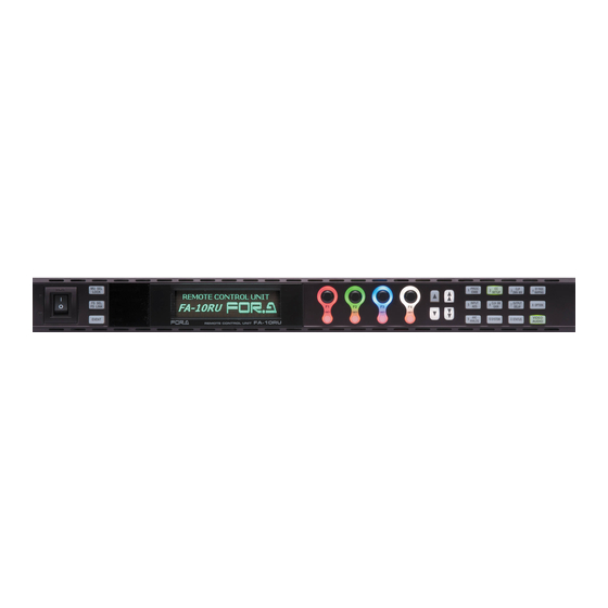
- Page 7 PROC CLIP BY-PASS GENLOCK FAN ALARM SETUP DWN MIX MAPPING FREEZE DC POWER DISPLAY AREA INPUT CLN SW OUTPUT OPTION VIDEO GAINI DELAY TEST SIGNAL UNITY UNITY UNITY UNITY VIDEO BY-PASS SYSTEM STATUS ANALOG AUDIO FA-10RU REMOTE CONTROL UNIT AUDIO...
-
Page 8: Table Of Contents
Table of Contents 1. Prior to Starting .......................... 13 1-1. Welcome ..........................13 1-2. Features ..........................13 1-3. About This Manual ......................13 2. Panel Descriptions ........................14 2-1. Front Panel ......................... 14 2-2. Rear Panel ......................... 15 2-3. Internal Settings ......................... 16 2-3-1. - Page 9 6-9. COLOR CORRECTION BLACK LEVEL ................40 6-10. COLOR CORRECTION GAMMA LEVEL ................ 40 6-11. COLOR SPACE ....................... 41 6-11-1. FA-505 (Software Version 2.10 or later) ..............41 6-11-2. FA-505 (Software Version 2.03) ................42 6-12. DYNAMIC RANGE CONTROL ..................43 6-12-1.
- Page 10 6-47. VIDEO INPUT LOSS MODE .................... 68 6-48. FS MODE SETTINGS ...................... 68 6-49. VIDEO SYSTEM PHASE/POSITION ................70 6-50. VIDEO FREEZE ....................... 71 6-51. SD TV LINE MASK ......................72 6-52. 3G SDI OUTPUT LEVEL ....................72 6-53. VIDEO TEST SIGNAL ...................... 73 6-54.
- Page 11 11-1. FA GPIO Editor ......................121 11-1-1. Software Installation ....................121 11-1-2. Verifying GPIO Editor Version ................123 11-1-3. Connecting FA GPIO Editor to the FA-10RU ............124 11-1-4. Setting GPI Functions ..................... 125 11-1-5. Exporting / Importing GPI Settings ................. 126 11-2.
- Page 12 12. Command Control ......................... 135 12-1. Communication Method ....................135 12-2. Command ........................135 12-2-1. Power On ........................ 135 12-2-2. MU Select Command ....................135 12-2-3. Connection Status Request Command (Status) ............ 136 13. Specifications and Dimensions ..................... 137 13-1. Specifications ......................... 137 13-2.
-
Page 13: Prior To Starting
1-2. Features The FA-10RU is a remote control unit that allows you to control FA-1010 / FA-505 Frame Synchronizer units via network. (This manual explains the FA-505 operations from FA-10RU units. Refer to “FA-10RU for FA-1010 Operation Manual” for the FA-1010 operations.) ... -
Page 14: Panel Descriptions
LOCK Lit orange when LOCK is on. button To release LOCK, hold down the button again. Used to switch menu button (9) functions after the FA-10RU is connected to an FA-505. Unlit: Allows you to select menu items. FS SEL Lit red: Allows you to select FS 1-5 using menu buttons. -
Page 15: Rear Panel
Lit red A power failure has occurred. Flashing Power Off the unit and consult your FOR-A Status DC POWER 6-58 reseller. indicator Unlit Power supply is normal. *1 The combination of Unlit/Flashing or Lit/Flashing is selectable. Refer to section “9-1-6. STATUS LED MODE SETTINGS”... -
Page 16: Internal Settings
2-3. Internal Settings IMPORTANT Note that internal switch settings should not be changed from factory defaults. If you have accidentally changed the settings, return them to the factory default settings as shown in this section. Be sure to have qualified technical personnel perform the settings and adjustments in the interior, or contact your dealer. - Page 17 Dipswitch S102 Settings Pin No. Default setting Setting OFF: Sets GPI OUT9 to open collector output. ON: Sets GPI OUT9 to +5V TTL level output. OFF: Sets GPI OUT10 to open collector output. ON: Sets GPI OUT10 to +5V TTL level output. OFF: Sets GPI OUT11 to open collector output.
- Page 18 Dipswitch S104 Settings Pin No. Default setting Setting OFF: Sets GPI OUT25 to open collector output. ON: Sets GPI OUT25 to +5V TTL level output. OFF: Sets GPI OUT26 to open collector output. ON: Sets GPI OUT26 to +5V TTL level output. OFF: Sets GPI OUT27 to open collector output.
-
Page 19: Connections
Specify unique IP addresses for all devices connected to the network. See section 10-2. Network Settings for details on setting IP addresses. One FA-505 unit can be controlled by up to 5 units of FA-10RU/FA-50GUI maximum. An attempted 6 connection will not be accepted. -
Page 20: Connection With Option/Expansion Units
3-2. Connection with Option/Expansion Units Connection with the FA-AUX30 option FA-AUX30 GPI1 GPI2 GPI3 FA-AUX30 supplied cables x 3 FA-10RU AC100-240V 50/60Hz IN GPI1 GPI2 GPI3 TO MU (10/100/1000BASE-T) Connection with a user-made switch box FS10 Connect to GPI1-GPI3 connector... -
Page 21: Setup
4. Setup 4-1. System Requirements To utilize the FA-10RU, your computer must meet the following requirements. Windows® 7 /8.1 Windows® 10 Professional (32/64bit) Professional (32/64bit) Intel® Core™ 2 Duo processor Intel® Core™ 2 Duo processor 2GHz or higher 2GHz or higher Web browser Internet Explorer®... -
Page 22: Front Panel Operations
To cancel the selection, press the UNITY button under F4 (CANCEL). Cancelling the connection returns the settings to their last state before change. Select Disconnect by F1 and press the UNITY button under F3 to disable the connection of FA-10RU to any FA-505. (The connected FA-505 will also be disconnected.) -
Page 23: Connecting In Ip Address Selection Mode
5-2-2. Connecting in IP Address Selection Mode Press the MU SEL button. The UNIT ID SEL menu appears. Then, press the double down-arrow button. The IP ADDRESS MU SELECT menu appears. - - - I P A D D R E S S M U S E L E C T - - - P 8 0 2 F 1 - F 4 I P A d d r e s s : 1 9 2 . -
Page 24: Basic Operations
Most of the menus can be controlled by these basic operations. However, some menus work differently. See the descriptions given for each menu for details. The FA-10RU has two menu operation modes: Normal mode, in which setting changes immediately take effect, and Live Safe mode, in which some settings request confirmation before changes take effect. -
Page 25: Accessing Menus
5-3-1. Accessing Menus MU SEL PR OC CL IP BY-P ASS GENLOCK FAN ALARM POW ER SE TUP DWN MIX MAP PING LOCK FREEZE DC POWER DISPLAY AREA INP UT CLN SW OUT PUT FS SEL OPT ION A ES GAIN DE LAY FS LINK... -
Page 26: Menu Buttons
5-3-2. Menu Buttons The VIDEO/AUDIO button at the bottom right switches between the video and audio-related menus. Pressing the button alternates the button to work as video menu buttons (lit green) and audio menu buttons (lit orange). The menus at the top of each button label are video menus (lit green), and the menus at the bottom are audio menus (lit orange). - Page 27 Menu Button VIDEO menus (lit green) AUDIO menus (lit orange) CLOSED CAPTION SETTINGS AFD DETECT SETTINGS AFD LOSS SETTINGS TIMECODE DETECT SETTINGS INPUT ANCILLARY STATUS1 INPUT ANCILLARY STATUS2 ► SDI MULTIPLEXER EMBEDDED AUDIO MULTIPLEXER 9 ANC CLOSED CAPTION EMBEDDED ANALOG AUDIO INPUT/OUTPUT ►...
-
Page 28: Arrow Buttons
5-3-3. Arrow Buttons Double-arrow buttons (up and down) <Normal mode> The double-arrow buttons allow you to move between menus. <Live Safe mode> Button functions are the same as those in Normal mode, however, double-arrow buttons are inoperative while blinking (indicating the FA-505 is requesting user change confirmation, because a menu parameter has been changed in the menu that requires confirmation for changes). -
Page 29: Changing Setting Values
5-3-5. Changing Setting Values Once the desired menu is displayed, use the controls (F1-F4) to change the setting values. MU SEL GENLOCK FAN ALARM PR OC CL IP BY-P ASS POW ER SE TUP DWN MIX MAP PING LOCK FREEZE DC POWER DISPLAY AREA INP UT... -
Page 30: Resetting To Default
5-3-6. Resetting to Default <Normal mode> The UNITY indicator light goes off when the setting value is changed from the default value. Pressing the UNITY button while the light is off returns the corresponding setting value to the default value. Then the light turns on. Pressing the button again returns the value to the previous value before resetting to the default value. -
Page 31: Selecting 5-Channel Frame Synchronizers
5-3-7. Selecting 5-channel Frame Synchronizers If “FS1 Name: FS 1” is displayed in the top row of the menu display as shown below, settings can be set for FSs 1 to 5. The number and name of the selected FS are displayed. Names can be set for each FS in the FA-505. -
Page 32: Fs Link Function
5-3-8. FS Link Function This function allows settings of multiple FSs to be changed simultaneously. 5-3-8-1. Menus Allowing Simultaneous Setting Change The below menus can be changed their settings for multiple FSs simultaneously. VIDEO PROCESS AMPLIFIER VIDEO LEVEL Y LEVEL CHROMA LEVEL SETUP/BLACK LEVEL COLOR CORRECTION... -
Page 33: Unity Function During Link Mode
F S 1 ◆ F S 2 F S 3 - - - F S 1 V I D E O P R O C E S S A M P L I F I E R - - - P 5 0 1 F 1 - F 3 V i d e o : 1 0 0 . -
Page 34: Fs Name List Display
5-3-9. FS Name List Display - - - S D I V I D E O B Y - P A S S - - - P 5 1 5 S D I 1 - I / O : O F F S D I 2 - I / O : O F F The FS NAME List as shown below can be displayed by pressing the FS SEL/FS LINK button while displaying a menu for which the FS selection is not displayed in the top row,... -
Page 35: Video Menus
6. VIDEO Menus Make the menu buttons light up green using the VIDEO/AUDIO button. (Pressing the button while the buttons are lit orange turns the lights green.) VIDEO Then the menus displayed on the upper row on each menu button can be selected. -
Page 36: Y Level
6-3. Y LEVEL F S 1 N a m e : F S 1 - - - Y L E V E L - - - P 5 0 3 F 1 F S 1 : 1 0 0 . 0 % PROC F S 2 : 1 0 0 . -
Page 37: Hue
6-6. HUE F S 1 N a m e : F S 1 - - - H U E - - - P 5 0 6 PROC F 1 F S 1 : 0 . 0 d e g r e e F S 2 : 0 . -
Page 38: Color Correction
6-7. COLOR CORRECTION COLOR CORRECTION settings can be copied between FSs. Refer to Sec. 6-11. "Copying Video Process / Color Corrector Settings" for more details. F S 1 N a m e : F S 1 - - - C O L O R C O R R E C T I O N - - - P 5 0 7 F 1 - F 4 W h i t e R : 1 0 0 . -
Page 39: Color Correction White Level
Split mode display OFF: Displays the image after correction. MODE1: Splits the screen vertically and displays images before and after correction. MODE2: Splits the screen horizontally and displays images before and after correction. MODE3: Displays the image before correction. Image before correction Image after... -
Page 40: Color Correction Black Level
6-9. COLOR CORRECTION BLACK LEVEL F S 1 N a m e : F S 1 - - - C O L O R C O R R E C T I O N B L A C K L E V E L - - - P 5 0 9 F S 1 R : 1 0 0 . -
Page 41: Color Space
6-11. COLOR SPACE 6-11-1. FA-505 (Software Version 2.10 or later) F S 1 N a m e : F S 1 - - - C O L O R S P A C E - - - P 5 1 2 F 1 I n G a m m a C u r v e ( E O T F ) : B y - p a s s C o l o r S p a c e... -
Page 42: Software Version 2.03)
Sets the maximum luminance value in linear color space by specifying the actual maximum value (in nit or %) of input video. Maximum, This setting allows Knee Clip 100, 200, 300, Peak 400, 500, 800, If Maximum is set, the maximum value in input Maximum Luminance 1000, 2000, 4000,... -
Page 43: Dynamic Range Control
6-12. DYNAMIC RANGE CONTROL 6-12-1. FA-505 (Software Version 2.10 or later) F S 1 N a m e : F S 1 - - - D Y N A M I C R A N G E C O N T R O L - - - P 5 1 3 P e a k L u m i n a n c e : 1 0 0... -
Page 44: Copying Video Process / Color Corrector Settings
6-13. Copying Video Process / Color Corrector Settings The following two submenu settings can be copied between FSs using an extra menu page, FS DATA COPY. FS DATA COPY menu To open the FS DATA COPY menu, press and hold the PROC EMB button (with lit green) or the CC SETUP button (with lit green). -
Page 45: Video Clip
6-14. VIDEO CLIP 6-14-1. If Mode is Off F S 1 N a m e : F S 1 - - - V I D E O C L I P - - - P 5 1 4 F 1 M o d e : O f f CLIP DWN MIX Parameter... -
Page 46: If Mode Is Rgb Clip (Fa-505 V2.10 Or Later)
50.0 - 150% Allows you to set the knee clip start Knee Point 100.0% (0.5%) point. Allows you to set the input minimum value. -50.0 - 50.0% Input Clip 0.0% (0.5%) The value of 100% is the Reference White setting. Allows you to set the output minimum Black Clip value. -
Page 47: If Mode Is Rgb Clip (Fa-505 V1.21 Or Earlier)
Allows you to set the upper knee point. 50.0 (Min.) Default and maximum values change White Knee Point (Variable) (0.5%) according to the White Level (RGB White Clip) setting. White Knee Slope Off, 1 - 15 Allows you to set the upper knee slope. Black Level -50.0 - 50.0% -50.0%... -
Page 48: Color Correction By-Pass
6-16. COLOR CORRECTION BY-PASS - - - C O L O R C O R R E C T I O N B Y - P A S S - - - P 5 1 6 F 1 F S 1 C C : O p e r a t e F S 2 C C : O p e r a t e F S 3 C C : O p e r a t e BY-PASS... -
Page 49: Fs Sync Format Settings
6-18. FS SYNC FORMAT SETTINGS - - - F S S Y N C F O R M A T S E T T I N G S - - - P 5 2 0 F 1 F S 1 : A u t o D e t e c t F S 2 : A u t o D e t e c t F S 3 : A u t o D e t e c t F S 4 : A u t o D e t e c t... -
Page 50: Clean Switch Settings
Destination1 - Destination5 blinks if the destination displayed for the DEST differs from the actual output (see section 6-19. CLEAN SWITCH SETTINGS), The registered Salvo Name is also displayed. FA-10RU Allows you to select a unit from which to load the Unit FA-10RU Salvo. -
Page 51: Salvo Save
Destination1 - 5 blinks if the destination displayed for the Destination differs from the actual output (see section 6-19. CLEAN SWITCH SETTINGS), The registered Salvo Name is also displayed. FA-10RU Allows you to select a unit to which to save the Unit FA-10RU Salvo setting. -
Page 52: Sdi Video Output Port Assign
6-23. SDI VIDEO OUTPUT PORT ASSIGN - - - S D I V I D E O O U T P U T P O R T A S S I G N - - - P 5 3 0 F 1 O U T 1 a / b : R o u t e r O u t 1 O U T 2 a / b : R o u t e r O u t 2 O U T 3 a / b : R o u t e r O u t 3... -
Page 53: Up/Down Converter Mode
Menus from Sec 6-24 to Sec. 6-29 require FA-505UD option. 6-24. UP/DOWN CONVERTER MODE F S 1 N a m e : F S 1 - - - U P / D O W N C O N V E R T E R M O D E - - - P 5 3 5 C o n v e r t e r I n C o n v e r t e r O u t... - Page 54 Specifies the output signal frame rate when 25/50 25/50 Convert Mode is set to 1080p and input 30/60 signal frame rate is a PAL variant. The “Unadjustable” is displayed when Converter Mode is set to By-pass, or unsupported format is specified. If set to 1080p(3G), the 3G-SDI Output Level setting (see 6-52) determines whether Level A or B applies.
-
Page 55: Up/Down Converter Size/Pos
6-25. UP/DOWN CONVERTER SIZE/POS F S 1 N a m e : F S 1 - - - U P / D O W N C O N V E R T E R S I Z E / P O S - - - P 5 3 6 F 1 H S i z e : 1 0 0 . -
Page 56: Improvement In Converter
6-27. IMPROVEMENT IN CONVERTER F S 1 N a m e : F S 1 - - - I M P R O V E M E N T C O N V E R T E R - - - P 5 3 8 F 1 M o t i o n S e n s e : A d a p t i v e F 2 A n t i a l i a s H : N o r m a l... -
Page 57: Slot A-D Gpi Function Settings
P u s h F 2 U n i t y A p p l y If GPI Operate Mode is set to Extended in the FA-505GUI, FA-10RU units cannot change GPI settings on the FA-505. To change GPI settings, change GPI Operate Mode to Normal in the GPI tab of FA-505GUI. - Page 58 *2, *3 FS1-5, AES A-D, Analog, All Off *2, *3 Audio Test Signal FS1-5 AES A-D, Analog, All 500Hz Tone *2, *3 FS1-5 AES A-D, Analog, All 1kHz Tone Other GPI Lock *1 Displays an “*” at the beginning of text strings if the function is ineffective due to other settings. *2 AES A-D functions are displayed if the FA-10AES-BL/UBL/UBLC option is installed in the corresponding SLOT A-D.
-
Page 59: Closed Caption Settings
Video Test Signal FS1-5 Outputs when Video Test Signal is set to SMPTE Color Bar for the subject SMPTE Color Bar Video Test Signal FS1-5 Outputs when Video Test Signal is set to RAMP for the subject FS. Ramp Video Test Signal All Off Outputs when Video Test Signal All is set to Off. -
Page 60: Afd Detect Settings
6-31. AFD DETECT SETTINGS F S 1 N a m e : F S 1 - - - A F D D E T E C T S E T T I N G S - - - P 5 5 7 S D S D I : S 2 0 1 6 - 3 A F D V I ( 5 2 5 / 6 0 ) F 1 : L i n e 1 4... -
Page 61: Timecode Detect Settings
Select an AFD code if S2016-3 data cannot Remove be detected in HD-SDI inputs. Hold 16:9 L>16:9 The selected AFD code is used for 16:9 F 16:9 conversion process. 16:9 P 4:3 S2016-3(HD) Remove 16:9 F PRTD Remove: If the automatic aspect ratio 16:9 P 14:9 processing is enabled in the built-in 16:9 P ALT 14:9... -
Page 62: Input Ancillary Status 1
6-34. INPUT ANCILLARY STATUS 1 F S 1 N a m e : F S 1 - - - I N P U T A N C I L L A R Y S T A T U S 1 - - - P 5 6 1 S t a n d a r d S t a t u s... -
Page 63: Embedded Audio Multiplexer
Select a processing type for the VANC space on SDI output. Pass Pass: Passes through the VANC data space ”as Overwrite Blank is.” Blank: Blanks all VANC data space. 6-37. EMBEDDED AUDIO MULTIPLEXER F S 1 N a m e : F S 1 - - - E M B E D D E D A U D I O M U L T I P L E X E R - - - P 5 6 5 F 1 G r o u p 1 : E n a b l e... -
Page 64: S2016-3 Afd Embedded
6-39. S2016-3 AFD EMBEDDED F S 1 N a m e : F S 1 - - - S 2 0 1 6 - 3 A F D E M B E D D E D - - - P 5 6 7 5 2 5 / 6 0 F 1 : L i n e 1 2 / 2 7 5 F 2 E M B : D i s a b l e... -
Page 65: Bt1119-2 Wss Afd Embedded
6-41. BT1119-2 WSS AFD EMBEDDED F S 1 N a m e : F S 1 - - - B T 1 1 1 9 - 2 W S S A F D E M B E D D E D - - - P 5 6 9 F 1 L i n e : L i n e 2 3... -
Page 66: S12M-1 Atc Vitc Embedded
6-43. S12M-1 ATC VITC EMBEDDED F S 1 N a m e : F S 1 - - - S 1 2 M - 1 A T C V I T C E M B E D D E D - - - P 5 7 1 5 2 5 / 6 0 F 1 : L i n e 1 2 / 2 7 5... -
Page 67: Embedded Time Code
6-45. EMBEDDED TIME CODE - - - E M B E D D E D T I M E C O D E - - - P 5 7 5 F S 1 F 1 V I T C : A T C ( V I T C ) F 2 L T C : A T C ( V I T C ) F S 2 V I T C : A T C ( V I T C ) -
Page 68: Video Input Loss Mode
6-47. VIDEO INPUT LOSS MODE - - - V I D E O I N P U T L O S S M O D E - - - P 5 7 8 F 1 F S 1 : B l a c k F S 2 : B l a c k F S 3 : B l a c k F S 4 : B l a c k... - Page 69 Allows you to enable/disable 4KFS mode. 4 input signals are simultaneously phase-adjusted within 2 lines (1 line for Level B) for horizontal and 1 frame for vertical timings. Enable: Processes the FS2, FS3, FS4 and FS5 video signals as a 4K video. Purple light indicates 4KFS mode is active.
-
Page 70: Video System Phase/Position
<Adjustable range per signal format> Adjustable range Format Line AVDL Line (Minimum) 1080/59i, 1080/29p -1.5H to -0.5H -6H to -0.5H -1.3H to -0.3 H (-700 clk) 1080/30p -1.5H to -0.5H -6H to -0.5H -1.3H to -0.3 H (-700 clk) 720/59p -1.5H to -0.5H -6H to -0.5H -1.4H to -0.4 H (-700 clk) -
Page 71: Video Freeze
To change the FS selection to set settings, refer to section 5-3-7. “Selecting 5-channel Frame Synchronizers.” The sync mode of the FS is displayed in the bottom line. Horizontal Phase Default Values (Ver 2.12 or earlier) Sync Mode Default Frame Line AVDL... -
Page 72: Sd Tv Line Mask
6-51. SD TV LINE MASK F S 1 N a m e : F S 1 - - - S D T V L I N E M A S K - - - P 5 8 3 F 1 - F 4 L 6 : O f f L 7 : O f f L 8 : O f f L 9 : O f f... -
Page 73: Video Test Signal
6-53. VIDEO TEST SIGNAL - - - V I D E O T E S T S I G N A L - - - P 5 8 5 F 1 F S 1 : O f f F S 2 : O f f F S 3 : O f f F S 4 : O f f 10 SYSTEM... -
Page 74: Sdi Video Output Status
6-56. SDI VIDEO OUTPUT STATUS - - - S D I V I D E O O U T P U T S T A T U S - - - P 5 9 3 S D I 1 a / 1 b : 5 2 5 / 6 0 S D I 2 a / 2 b : 1 0 8 0 / 2 3 P s F S D I 3 a / 3 b : 1 0 8 0 / 5 9 p L e v e l A STATUS... -
Page 75: Main Unit Alarm Information
Indicates that FS channel has no 2SI payload ID No Channel ID is present in the signal. code. Indicates that 2SI channel correspondence is Input signal and FS settings mismatched between Payload ID and FS mismatched. Switch this input to FSX. channel information. -
Page 76: Option Version Information
6-60. OPTION VERSION INFORMATION S l o t ( A ) - - - U N I T V E R S I O N I N F O R M A T I O N - - - P 6 0 3 O p t i o n T y p e : N o t i n s t a l l e d F P G A 1 : - - . -
Page 77: Audio Settings
7. AUDIO Settings Make the menu buttons light up orange using the VIDEO/AUDIO button. (Pressing the button while the buttons are lit green turns the lights orange.) VIDEO Afterwards, the audio menus displayed on the lower row on each menu AUDIO button can be selected. -
Page 78: Embedded Audio Error Sense
7-2. EMBEDDED AUDIO ERROR SENSE - - - E M B E D D E D A U D I O E R R O R S E N S E - - - P 6 1 2 F 1 F S 1 : N o r m a l F S 2 : N o r m a l PROC F S 3 : N o r m a l... -
Page 79: Embedded Audio Multiplex
7-4. EMBEDDED AUDIO MULTIPLEX F S 1 N a m e : F S 1 - - - E M B E D D E D A U D I O M U L T I P L E X - - - P 6 1 4 PROC F 1 A u d i o G r o u p 1 : A u t o... -
Page 80: Aes Audio Src Mode
7-6. AES AUDIO SRC MODE A E S ( A ) - - - A E S A U D I O S R C M O D E - - - P 6 1 7 F 1 C H 1 / 2 : A u t o F 2 C H 3 / 4 : A u t o F 3 C H 5 / 6 : A u t o F 4 C H 7 / 8 : A u t o... -
Page 81: Aes Audio In Polarity
7-8. AES AUDIO IN POLARITY A E S ( A ) - - - A E S A U D I O I N P O L A R I T Y - - - P 6 1 9 F 1 C H 1 : N o r m a l F 2 C H 2 : N o r m a l C H 3 : N o r m a l C H 4 : N o r m a l... -
Page 82: Aes Audio Mono Sum
7-11. AES AUDIO MONO SUM A E S ( A ) - - - A E S A U D I O M O N O S U M - - - P 6 2 3 F 1 C H 1 / 2 : S t e r e o F 2 C H 3 / 4 : S t e r e o F 3 C H 5 / 6 : S t e r e o SETUP... -
Page 83: Audio Down Mix Mode
7-13. AUDIO DOWN MIX MODE F S 1 N a m e : F S 1 - - - A U D I O D O W N M I X M O D E - - - P 6 2 6 F 1 M o d e CLIP F 2 S u r r o u n d M i x L e v e l : - 3 d B... -
Page 84: Embedded Audio Group1/2 Mapping
7-15. EMBEDDED AUDIO GROUP1/2 MAPPING F S 1 N a m e : F S 1 - - - E M B E D D E D A U D I O G R O U P 1 / 2 M A P P I N G - - - P 6 3 0 C H A s s i g n S o u r c e C H A s s i g n S o u r c e BY-PASS... -
Page 85: Embedded Audio Group3/4 Mapping
7-16. EMBEDDED AUDIO GROUP3/4 MAPPING F S 1 N a m e : F S 1 - - - E M B E D D E D A U D I O G R O U P 1 / 2 M A P P I N G - - - P 1 3 1 C H A s s i g n S o u r c e C H A s s i g n S o u r c e BY-PASS... -
Page 86: Aes Audio Output Mapping
7-17. AES AUDIO OUTPUT MAPPING A E S ( A ) - - - A E S A U D I O O U T P U T M A P P I N G - - - P 6 3 2 C H A s s i g n S o u r c e C H A s s i g n S o u r c e BY-PASS... -
Page 87: Analog Audio Output Mapping
7-18. ANALOG AUDIO OUTPUT MAPPING - - - A N A L O G A U D I O O U T P U T M A P P I N G - - - P 6 3 3 C H A s s i g n S o u r c e C H A s s i g n S o u r c e BY-PASS 1 : F S 1 I n - C H 1... -
Page 88: Aes Audio Hysteresis
7-19. AES AUDIO HYSTERESIS A E S ( A ) - - - A E S A U D I O H Y S T E R E S I S - - - P 6 3 6 F 1 C H 1 / 2 : O f f F 2 C H 3 / 4 : O f f F 3 C H 5 / 6 : O f f F 4 C H 7 / 8 : O f f... -
Page 89: Embedded Audio Output Gain
7-21. EMBEDDED AUDIO OUTPUT GAIN F S 1 N a m e : F S 1 - - - E M B E D D E D A U D I O O U T P U T G A I N - - - P 6 4 1 C H ( d B ) C H ( d B ) -
Page 90: Analog Audio Output Gain
7-23. ANALOG AUDIO OUTPUT GAIN - - - A N A L O G A U D I O O U T P U T G A I N - - - P 6 4 3 F 1 C h 1 : 0 . -
Page 91: Embedded Audio Output Delay
7-25. EMBEDDED AUDIO OUTPUT DELAY F S 1 N a m e : F S 1 - - - E M B E D D E D A U D I O O U T P U T D E L A Y - - - P 6 5 1 C H ( m s e c ) C H ( m s e c ) -
Page 92: Analog Audio Output Delay
7-27. ANALOG AUDIO OUTPUT DELAY - - - A N A L O G A U D I O O U T P U T D E L A Y - - - P 6 5 3 F 1 C h 1 : 5 m s e c F 2 C H 2 : 5 m s e c... -
Page 93: Microphone Settings
7-29. MICROPHONE SETTINGS - - - M I C R O P H O N E S E T T I N G S - - - P 6 8 2 F 1 C H 1 / 2 I n p u t M o d e : L i n e L e v e l F 2 M i c r o p h o n e P o w e r : O f f - - - - - - - - - - - - - - - - - - - - - - - - - - - - - - - - - - - - - - - - - - | C a u t i o n ! ! -
Page 94: Audio System
7-30. AUDIO SYSTEM - - - A U D I O S Y S T E M - - - P 6 8 6 F 1 R e f e r e n c e L e v e l : - 2 0 d B F S G r a d e : P r o f e s s i o n a l R e s o l u t i o n : 2 4 b i t 10 SYSTEM... -
Page 95: Aes Audio Test Signal
7-32. AES AUDIO TEST SIGNAL - - - A E S A U D I O T E S T S I G N A L - - - P 6 8 8 F 1 S l o t A : O f f F 2 S l o t B : O f f F 3 S l o t C : O f f 10 SYSTEM... -
Page 96: Embedded Audio Input Status
7-35. EMBEDDED AUDIO INPUT STATUS F S 1 N a m e : F S 1 - - - E M B E D D E D A U D I O I N P U T S T A T U S - - - P 7 0 1 STATUS 1 : L o s s... -
Page 97: Embedded Audio Output Status
7-38. EMBEDDED AUDIO OUTPUT STATUS F S 1 N a m e : F S 1 - - - E M B E D D E D A U D I O O U T S T A T U S - - - P 7 0 4 1 : S 2 : S... -
Page 98: Event Memory
8. Event Memory The FA-10RU can store and recall 100 event memories. It can also control 100 event memories in the connected FA-505. * FA-1010 and FA-505 settings are stored in different memory banks. Therefore, FA-1010 settings cannot be loaded to FA-505 units. -
Page 99: Save Event Memory
No. - - F3 UNITY Displays the “Saving event memory” message while processing. * See section 10-5. “Event Naming” for details on setting event names on the FA-10RU. Events saved on the FA-505 can be named using FA-50GUI. -
Page 100: Event Memory Load Settings List
8-3. Event Memory Load Settings List VIDEO Settings Event Loading Menu button VIDEO related menus (Lit green) Load All Load FS1-5 Only VIDEO PROCESS AMPLIFIER VIDEO LEVEL 1 PROC Y LEVEL CHROMA LEVEL SETUP/BLACK LEVEL COLOR CORRECTION COLOR CORRECTION WHITE LEVEL 2 CC COLOR CORRECTION BLACK LEVEL COLOR CORRECTION GAMMA LEVEL... - Page 101 AUDIO Settings Event Loading Menu button AUDIO related settings (Lit orange) Load All Load FS1-5 Only EMBEDDED AUDIO DEMULTIPLEX 1 PROC EMBEDDED AUDIO ERROR SENSE FADE IN/OUT EMBEDDED AUDIO MULTIPLEX EMBEDDED AUDIO SRC MODE AES AUDIO SRC MODE EMBEDDED AUDIO IN POLARITY 2 CC AES AUDIO IN POLARITY SETUP...
-
Page 102: Fa-10Ru System Settings And Viewing
9-1. FA-10RU SYSTEM Menus Pressing the MU SELECT button, then the 10 SYSTEM button (lit red), opens the menu as shown below, allowing you to verify the FA-10RU GPI function assignments, front panel display settings, and software versions. 9-1-1. LOAD GPI INPUT PATTERN Allows you to assign functions to GPI 10 inputs / outputs simultaneously using patterns. -
Page 103: Gpi Input Port Function
9-1-2. GPI INPUT PORT FUNCTION Allows you to assign functions to GPI input pins. - - - G P I I N P U T P O R T F U N C T I O N - - - P 8 2 2 MU SEL F 1 P o r t : G P I 1 P O R T 1 ( F A - A U X 3 0 L e f t B l o c k ) - Page 104 Audio Test Signal(500Hz) Menu On/Off Audio Test Signal(1kHz) GPI Lock On, Off, On/Off Memory Load Event, Salvo Menu, Default, No1-100 FA-10RU, MU Memory Save Event, Salvo Menu, No1-100 FA-10RU, MU Menu Move P000-P1499 None, FS1-FS10 None, Line1-Line8 Color Corrector Split...
- Page 105 If Disconnect is selected under Setting 2, the FA-10RU is disconnected from the main unit. See section 5-2-1. “Connecting in Unit ID Selection Mode” for details on IDs. To change an FS along with the connection, select an FS under Setting 3.
- Page 106 By-Pass Setting1 Setting2 Setting3 Setting4 Menu None By-pass Menu SDI1 - SDI10 On/Off Selecting Bypass under Setting 1 allows you to turn On or Off the Bypass function by selecting On/Off under Setting 2. On/Off alternately turns Bypass On and Off, when the circuit is closed. Select an SDI connector to be bypassed under Setting 3.
- Page 107 Audio Delay(Analog) Setting1 Setting2 Setting3 Setting4 Audio Delay(Analog) Selecting Audio Delay(Analog) under Setting 1 opens the Audio Delay(Analog) menu, when the circuit is closed. Effective if an Analog Option is installed. See section 7-27. “ANALOG AUDIO OUTPUT DELAY” for details. ...
- Page 108 Setting1 Setting2 Setting3 Setting4 Menu Event FA-10RU Memory Load Default Salvo No1 - 100 Selecting Memory Load allows you to load the memory data selected under Setting 2, 3 and 4. See section 6-20. “SALVO LOAD”, and 8-1. “LOAD EVENT MEMORY” for details.
- Page 109 Setting2 Setting3 Setting4 Menu Event FA-10RU Memory Save Salvo No1 - 100 Selecting Memory Save under Setting 1 allows you to save the memory data to the memory specified under Setting 2, 3 and 4, when the circuit is closed. See section 6-21. “SALVO SAVE”, and 8-2.
- Page 110 Do not use for FA-1010 units. Output Color Space Setting1 Setting2 Setting3 Setting4 Rec. ITUR BT.709 None None Rec. ITUR BT.2020 Output Color Space FS1-FS5 Menu User1-5 Selecting Output Color Space under Setting 1 allows you to display the menu selected under Setting 2, 3, and 4 when the circuit is closed.
-
Page 111: Gpi Output Port Function
All DC/FAN Alarm power, or FA-10RU FAN unit. FA-10RU FAN Alarm Outputs a signal if an alarm is detected in the FA-10RU FAN unit. Outputs a signal if an alarm is detected in an FA-1010 / FA-505 or MU/FA-10RU FAN Alarm FA-10RU FAN unit. -
Page 112: Gpi Output Brightness
Allows you to set brightness for front panel LEDs. LED Brightness Level4 Level 1 - 8 Level 1 – 8: Dark - Bright Disable Disable: Disables the FA-10RU buzzer. FA-10RU Buzzer Enable Enable Enable: Enables the FA-10RU buzzer. Disable Disable: Disables the GPI buzzer. -
Page 113: Status Led Mode Settings
Move the F1 indication to the item to be set using single-arrow buttons. 9-1-7. FA-10RU INFORMATION Displays the FA-10RU version information and FA-10RU FAN unit status. - - - F A - 1 0 R U I N F O R M A T I O N - - - P 8 3 3 F P G A 1 V e r s i o n : 1 . -
Page 114: Web Browser Settings
Click on a page link such as Network Settings, User Account Settings shown on the left side of the screen, the following “Windows Security” dialog will appear. Enter your user name and password. User name: fa10ru User password: foranetwork Then click OK. After successful authentication, you will have access to all the FA-10RU pages. -
Page 115: Information
Click Information. The information page as shown below appears. Unit Information Item Description Serial Number Displays the serial number of the FA-10RU. FPGA1 Version Displays the version of the FA-10RU FPGA1. FPGA2 Version Displays the version of the FA-10RU FPGA2. -
Page 116: Network Settings
10-2. Network Settings Clicking Network Settings opens the dialog box as shown below. To change the network address, change the settings and click Submit. Changes will be applied after reboot or restart (see section 10-8) is performed. 10-3. User Account Settings Clicking User Account opens the dialog box as shown below. -
Page 117: Unit Id Assignment
Clicking Event Naming (FA-505) opens the dialog box as shown below. Setting Procedure This page allows you to rename evens (Event1 to Event100) saved in the FA-10RU. (1) Enter a desired name (up to 15 alphanumeric characters) in the Event Name field. -
Page 118: Salvo Naming
See section 6-20. “SALVO LOAD” and 6-21. “SALVO SAVE” for more details. 10-7. Backup & Restore Clicking Backup & Restore opens the dialog box as shown below. This dialog box allows you to save the FA-10RU settings and event data to a PC. The saved data can be recalled. -
Page 119: Configuration Data Backup
Be sure to perform restart as described in section 10-8. “Restart.” 10-7-2. Event Data Backup All event data for FA-505 saved in the FA-10RU can be saved/recalled to/from a file on a PC Saving all Event Data to a file on a PC (1) Click Save File: Save under “Backup Event Data (FA-505).”... -
Page 120: Restart
10-8. Restart Clicking Restart opens the window as shown below. Be sure to click Restart after changing Network Settings or User Account Settings. -
Page 121: Gpi Interface
11. GPI Interface The GPI1, GPI2 and GPI3 connectors provide a total of 30 inputs and 30 outputs. Functions can be assigned to each terminal as well as a group of terminals using patterns, which are set for specific purposes (Pattern Load). Refer to sections 9-1-1 to 9-1-3 for details on function assignments. The FA GPIO Editor also allows you to set GPI assignments on the GUI screen (see the following chapters). - Page 122 (4) The installation directory of the FA GPIO Editor is displayed. To change the default installation directory, click Change… and specify a new directory. (5) Click Next. (6) The last wizard page is displayed. Verify the installation settings and click Install to install the software.
-
Page 123: Verifying Gpio Editor Version
(7) When the software installation is complete, the window as shown below will appear. Click Finish to finish the installation. 11-1-2. Verifying GPIO Editor Version Click Version Information in the menu bar. A window as shown below will appear. To close the window, click OK. -
Page 124: Connecting Fa Gpio Editor To The Fa-10Ru
(3) When the user name and password are accepted, a window as shown below is displayed and FA-10RU GPI settings are loaded in the window. When the user name and password are not accepted, an error pop-up dialog windows appears. -
Page 125: Setting Gpi Functions
GPI inputs/outputs are quickly set. Loaded settings (including output functions) can be changed. (See "If Setting Individually" below.) (3) After all GPI settings are finished, click Apply to send the settings to the FA-10RU unit. If a “Successful settings” message appears, GPI settings are complete. -
Page 126: Exporting / Importing Gpi Settings
GPI settings can be loaded from files in the computer. (1) Select File > Import in the menu bar. (2) Specify the file name (such as FA-10RU GPIO.csv) and location. (3) Verify settings in the FA GPIO Editor, then click Apply... -
Page 127: Gpi Input Patterns
11-2. GPI Input Patterns This section describes GPI Input setting patterns that can be selected in the LOAD GPI PATTERN menu (section 9-1-1). The following figures depict FA-AUX30 buttons. GPI1-3 BLOCK Button Button name Description setting Each button establishes a connection to the Main Unit MU Select 1-10 MU ID1-10... - Page 128 GPI1-3 BLOCK Button name Button Description setting (See below) DIRECT MODE The selected DIRECT MODE or TAKE MODE button lights. If a Source selection is changed in TAKE MODE, the TAKE MODE TAKE button LED blinks. Pressing the blinking TAKE button switches preset Clean crosspoints simultaneously.
- Page 129 GPI1-3 BLOCK Button Button name Description setting FREEZE Freeze (FS1-FS10) Turns the FREEZE FS1-5 function On/Off. FS1-5 Audio Gain Opens the EMBEDDED AUDIO OUTPUT GAIN menu GAIN FS1-5 (FS1-FS10) and lights the button. Audio Delay DELAY Opens the EMBEDDED AUDIO OUTPUT DELAY (FS1-FS10) FS1-5 menu and lights the button.
- Page 130 Opens the SALVO LOAD menu and lights the button. SALVO SAVE Opens the SALVO SAVE menu and lights the button. The button LED lights if an alarm is detected in a FAN or ALARM power unit of the connected FA-505, or a FAN unit in the FA-10RU.
- Page 131 FAN1-FAN4 in the connected FA-505. FAN1-4 Pressing the button opens the MAIN UNIT ALARM INFORMATION menu. The button LED lights if an alarm occurs in an FA-10RU FAN RU FAN unit. Pressing the button opens the FA-10RU INFORMATION menu. Status 2 The button LED lights if an alarm occurs in DC power 1 or 2.
-
Page 132: Gpi1-Gpi3 Pin Assignments
11-3. GPI1-GPI3 Pin Assignments GPI connector 25-pin D-sub, female Signals Pin No. GPI1 GPI2 GPI3 GND (Ground) GPI OUT 1 (Output) GPI OUT 11 (Output) GPI OUT 21 (Output) GPI OUT 2 (Output) GPI OUT 12 (Output) GPI OUT 22 (Output) GPI OUT 3 (Output) GPI OUT 13 (Output) GPI OUT 23 (Output) -
Page 133: Gpi Input Circuit
11-4. GPI Input Circuit FA-505 inside PINs 8 to 12 20 to 24 (IN) PIN 1, 7, 19 11-5. GPI Input Control Pulse signals The pulse signal level change (OPEN to CLOSE) triggers each operation. OPEN to CLOSE: The assigned function will be turned on. 100msec or more OPEN CLOSE... -
Page 134: Gpi Output Circuit (Same For Gpi 1-3)
11-6. GPI Output Circuit (Same for GPI 1-3) Select external or internal power. FA-505 inside +5.0V DIP SW setting PIN 13 Protective resistor 5-24 VDC (external power) PIN 1, 7, 19 PINs 2-6, 14-18 (OUT) IMPORTANT Note that the allowed current for each GPI output circuit is 50 mA and the external power supply should be 5 to 24 VDC. -
Page 135: Command Control
12. Command Control FA-10RU units can accepts the MU Select command over LAN. 12-1. Communication Method Communication Interface Ethernet: IEEE802.3u/ab method (100BASE-TX / 1000BASE-T) Protocol TCP/IP, UDP/IP Port number 60000 (Fixed) Connection timeout 30 seconds (See Error Code 99.) Maximum connection number Control command Sends to FA-10RU. -
Page 136: Connection Status Request Command (Status)
FS1 to FS5, --- (Disconnected) Connecting Connection refused Connected Send ACK[CR][LF] when you receive a connection status message. If FA-10RU receives no ACK, it re-sends the status message three times at one-second intervals. Error Response Return message (TCP): ERR<Error code>[CR][LF]] Any of the following error messages is returned if a command is not properly received. -
Page 137: Specifications And Dimensions
POWER LOCK SETUP DWN MIX MAPPING FREEZE DC POWER DISPLAY AREA INPUT CLN SW OUTPUT FS SEL OPTION GAINI DELAY FS LINK TEST SIGNAL UNITY UNITY UNITY UNITY VIDEO BY-PASS SYSTEM STATUS EVENT ANALOG AUDIO FA-10RU REMOTE CONTROL UNIT 12.7... - Page 138 Warning This equipment has been tested and found to comply with the limits for a Class A digital device, pursuant to Part 15 of FCC Rules. These limits are designed to provide reasonable protection against harmful interference when the equipment is operated in a commercial environment. This equipment generates, uses, and can radiate radio frequency energy and, if not installed and used in accordance with the instruction manual, may cause harmful interference to radio communications.
- Page 139 June 14, 2019 Printed in Japan FOR-A COMPANY LIMITED Head Office 3-8-1 Ebisu, Shibuya-ku, Tokyo 150-0013, Japan Overseas Division Tel: +81(0)3 3446 3936 Fax: +81(0)3 3445 5116 Japan Branch Offices Osaka/Okinawa/Fukuoka/Hiroshima/Nagoya/Sendai/Sapporo R&D/Production Sakura Center/Sapporo Center FOR-A Corporation of America 11155 Knott Ave., Suite G&H, Cypress, CA 90630, USA. Tel: +1 714 894 3311 Fax: +1 714 894 5399 FOR-A Corporation of America East Coast Office...
Need help?
Do you have a question about the FA-10RU and is the answer not in the manual?
Questions and answers