BIG ASS FANS Yellow Jacket Installation Manual
Hide thumbs
Also See for Yellow Jacket:
- Installation manual (28 pages) ,
- Installation manual (20 pages)

Related Manuals for BIG ASS FANS Yellow Jacket


Summary of Contents for BIG ASS FANS Yellow Jacket
- Page 1 INSTALLATION GUIDE Yellow Jacket ® For help, call 1-877-BIG-FANS Delta T LLC dba Big Ass Fans or visit www.bigassfans.com...
- Page 2 PRE-INSTALLATION CHECKLIST Do you have the correct power circuit for the fan speed control? See page 1 for information on selecting the correct circuit/fuse for the fan speed control. Did a structural engineer approve the mounting structure? See page 6 for mounting information. If you ordered multiple fans, did you keep the parts for each fan together? If you ordered the oscillator, did you review the installation guide included with the oscillator?
- Page 3 All trademarks used herein are the properties of their respective owners. No part of this document may be reproduced or translated into a different language without the prior written consent of Big Ass Fans. The information contained in this document is subject to change without notice.
- Page 4 Do not attempt to resolve electrical malfunctions or failures on your own. Contact Big Ass Fans if you have any questions regarding the use of this fan. CAUTION: When service or replacement of a component in the fan requires the removal or disconnection of a safety device, the safety device is to be reinstalled or remounted as previously installed.
-
Page 5: Table Of Contents
CONTENTS Introduction Safety Instructions About this Fan Pre-Installation Parts and Hardware Fan Diagram Preparing the Work Site Mounting Overview Mounting Method: 1. Attach Wheels (to Portable Base) 2a. Attach Fan (to Portable Base) Portable Base 2b. Attach Pedestal (to Portable Base) 3. - Page 6 Mounting Structure: 1. Prepare Angle Iron Brackets 2. Prepare Concrete Structure Concrete 3. Attach Angle Iron Brackets (to Concrete) 4. Attach Chain or Cable 5. Secure Guy Wires Positioning the Fan Setting the Fan’s Position Electrical Installation Electrical Installation Safety Power Requirements Speed Control Operation Starting, Stopping, and Speed Control...
-
Page 7: About This Fan
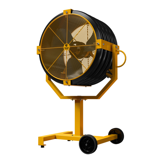
ABOUT THIS FAN Yellow Jacket is a durable, portable fan that incorporates all of the heavy-duty characteristics expected of a Big ® Ass Fan with the flexible mounting capabilities perfect for spaces requiring localized or additional air movement. Fan weight 105 lb (47.6 kg) -
Page 8: Parts And Hardware
& Yoke Attachment Brackets Speed Control Optional. Pedestals are only included if ordered. Up to two (2) pedestals can be installed on Yellow Jacket. 2. Optional. Wall/Column mount parts and hardware are only included if ordered. 3. Optional. Yoke mount parts and hardware are only included if ordered. Square washers are only used if mounting the fan to angle irons. - Page 9 3. Guy wires are designed to constrain the fan’s lateral movement. Guy wire hardware is packed separately from the fan hardware. Big Ass Fans recommends using guy wires if the fan’s extension tube is 4 ft or longer; therefore, guy wires are included in all fan packages with 4 ft or longer extension tubes. Big Ass Fans also recommends using guy wires if the fan is exposed to high winds or similar conditions, or if the fan is close to any building fixtures.
-
Page 10: Fan Diagram
FAN DIAGRAM The diagram below shows a Yellow Jacket with one pedestal and portable base. If you ordered the Wall/Column mount, Yoke mount, Yoke Washer Assembly kit, or an extra pedestal, see the appropriate installation instructions. A. Protective Cage and Housing. The steel cage and housing protect both the fan and users during operation. -
Page 11: Preparing The Work Site
When surveying the work site, keep the following guidelines in mind. Mechanical Installation • The Yellow Jacket weighs, at maximum, 105 lbs (48 kg). Practice proper lifting techniques when assembling the fan. • If you ordered the oscillator, review the installation guide packaged with the oscillator before beginning installation. -
Page 12: Mounting Overview
• I-Beam. Yellow Jacket can be mounted to an I-beam using the Yoke Mount. Note: If the distance between the I-beam and obstructions less than 65” (165 cm), the I-Beam Mount must be used. Contact Customer Service for details. -
Page 13: Attach Wheels (To Portable Base)
MOUNTING METHOD: PORTABLE BASE WARNING: To reduce the risk of fire, electric shock, and injury to persons, the fan must be installed with the supplied mounting hardware. Other mounting hardware cannot be substituted. 1. Attach wheels (to portable base) To install the wheels, insert the screw through the center of the wheel. Thread the hex nut onto the screw approximately 1”, and then insert the screw (attached to the wheel) into the hole on the fan base until it is tight. -
Page 14: 2A. Attach Fan (To Portable Base)
2a. Attach fan (to portable base) Attach the fan to the portable base with the Base Hardware as shown. Position the yoke so that the handle is on the same side as the wheels. Proceed to “Electrical Installation.” Base Hardware: a. -
Page 15: 2B. Attach Pedestal (To Portable Base)
2b. Attach pedestal (to portable base) ATTENTION Pedestals are only included if ordered. Attach the pedestal to the portable base with the Base Hardware. Proceed to step 4 unless you purchased a second pedestal. If installing a second pedestal, continue to step 3. Base Hardware: a. -
Page 16: Attach Second Pedestal (To Pedestal)
3. Attach second pedestal (to pedestal) ATTENTION Up to two (2) pedestals can be installed. A second pedestal is only included if ordered. If you did not order a second pedestal, continue to step 4. After securing the first pedestal to the portable base, attach the pedestal with the Pedestal Hardware. Pedestal Hardware: a. -
Page 17: Attach Yoke (To Pedestal)
4. Attach yoke (to pedestal) ATTENTION Ensure the position locking pin is secured prior to attaching the yoke to the pedestal. Attach the fan yoke to the pedestal with the Pedestal Hardware. Position the yoke so that the handle is on the same side as the wheels. -
Page 18: Attach Supports (To Wall)
Verifying the stability of the mounting structure is the sole responsibility of the customer and/ or end user, and Big Ass Fans hereby expressly disclaims any liability arising therefrom, or arising from the use of any materials or hardware other than those supplied by Big Ass Fans or otherwise specified in these installation instructions. -
Page 19: Secure Yoke (To Supports)
2. Secure yoke (to supports) ATTENTION Ensure the position locking pin is secured prior to attaching the fan yoke to the supports. Secure the fan yoke to the supports with the Wall/Column Mount Hardware. Tighten the nuts. Proceed to “Electrical Installation.” Wall/Column Mount Hardware: a. -
Page 20: Prepare Angle Irons
Verifying the stability of the mounting structure is the sole responsibility of the customer and/ or end user, and Big Ass Fans hereby expressly disclaims any liability arising therefrom, or arising from the use of any materials or hardware other than those supplied by Big Ass Fans or otherwise specified in these installation instructions. -
Page 21: Attach Supports (To Column)
Note: All hardware used to secure the wall/column mount supports is installer-supplied. Big Ass Fans cannot provide specific installation details because of the wide variability of mounting surfaces, conditions, and fastening methods. - Page 22 ATTENTION Attach the supports in the orientation shown in this installation guide. Do not mount the supports vertically! CAUTION: It is your responsibility to comply with all local and national codes and regulations regarding mounting procedures and installation height! CAUTION: The column on which the fan will be mounted must be verified as sufficient to support the weight of the fan.
-
Page 23: Secure Yoke (To Supports)
3. Secure yoke (to supports) ATTENTION Ensure the position locking pin is secured prior to attaching the fan yoke to the supports. Attach the fan yoke to the supports with the Wall/Column Mount Hardware. Tighten the nuts. After installation, the fan must be inspected to verify it is sufficiently secured to the column. Depending on the size and surface of the column, the fan may be more prone to rotate if subjected to a lateral force. -
Page 24: Attach Upper Yoke (To I-Beam)
Verifying the stability of the mounting structure is the sole responsibility of the customer and/ or end user, and Big Ass Fans hereby expressly disclaims any liability arising therefrom, or arising from the use of any materials or hardware other than those supplied by Big Ass Fans or otherwise specified in these installation instructions. -
Page 25: Attach Extension Tube (To Upper Yoke)
3. Secure safety cable WARNING: The safety cable is a crucial part of the fan and must be installed correctly. If you have any questions, please contact Big Ass Fans Customer Service. ATTENTION The safety cable is already attached to the extension tube. - Page 26 Attach lower yoke brackets (to extension tube, 3 ft or shorter) Secure the lower yoke brackets to the lower portion of the extension tube with the remaining Extension Tube Hardware. Tighten the bolts until snug, but do not fully tighten. Proceed to step 8.
-
Page 27: Attach Beam Clamp
5. Attach beam clamp Beam Clamp Attach the beam clamp to the I-beam. The guy wire should be at a –45 angle from the roof to the Yellow Jacket extension tube. ® Place the beam clamp accordingly. Fully tighten the set screw to secure the clamp. -
Page 28: Install Remaining Guy Wires
7. Install remaining guy wires Wire Rope Clip CAUTION: Over-tightening the guy wires could throw the fan off balance. Repeat steps 5–6 to install the three remaining guy wires. Evenly cinch all four guy wires into place using the Gripples . -
Page 29: Select Proper Angle Irons
Verifying the stability of the mounting structure is the sole responsibility of the customer and/ or end user, and Big Ass Fans hereby expressly disclaims any liability arising therefrom, or arising from the use of any materials or hardware other than those supplied by Big Ass Fans or otherwise specified in these installation instructions. -
Page 30: Pre-Drill Angle Irons
2. Pre-drill angle irons Drill two ø9/16” (1.4 cm) holes exactly 5-3/8” (13.7 cm) apart in the centers of two angle irons. If the motor frame will be mounted directly to the angle irons, drill two ø9/16” (1.4 cm) holes exactly 5-1/2” (14 cm) apart in the centers of two angle irons. -
Page 31: 4A. Fasten Single Angle Irons To Roof Structure Mounting Points
4a. Fasten single angle irons to roof structure mounting points ATTENTION If installation requires double angle irons (span is greater than 8 ft), proceed to step 4b. Fasten the angle irons to the roof structure mounting points at each end with installer-supplied Grade 8 hardware. -
Page 32: Attach Upper Yoke (To Angle Irons)
5. Attach upper yoke (to angle irons) CAUTION: Beam clips and spacers are never used when mounting the fan to angle irons! ATTENTION The angle irons should be aligned with the outermost holes in the upper yoke. Secure the upper yoke directly to the angle irons with the Upper Yoke Hardware. Consult the diagrams below for distances between the angle irons. -
Page 33: Attach Extension Tube (To Upper Yoke)
7. Secure safety cable WARNING: The safety cable is a crucial part of the fan and must be installed correctly. If you have any questions, please contact Big Ass Fans Customer Service. ATTENTION The safety cable is already attached to the extension tube. - Page 34 Attach lower yoke brackets (to extension tube, 3 ft or shorter) Secure the lower yoke brackets to the lower portion of the extension tube with the remaining Extension Tube Hardware. Tighten the bolts until snug, but do not fully tighten. Proceed to step 12.
-
Page 35: Attach Beam Clamp
9. Attach beam clamp Beam Clamp Attach the beam clamp to the mounting structure. The guy wire should be at a 30 –45 angle from the roof to the extension tube. Place the beam clamp accordingly. Fully tighten the set screw to secure the clamp. -
Page 36: Install Remaining Guy Wires
11. Install remaining guy wires CAUTION: Over-tightening the guy wires could throw the fan off Wire Rope Clip balance. Repeat steps 9–10 to install the three remaining guy wires. Evenly cinch all four guy wires into place using the Gripples ®... -
Page 37: Attach Chain Or Cable
Yellow Jacket can be hung from the existing building structure using a chain or cable of rated strength to support the weight of the fan (approximately 105 lbs [47.6 kg]). The following instructions are merely a recommendation for hanging the Yellow Jacket from the building structure. - Page 38 You must consult a structural engineer to determine the best method for mounting your fan. Big Ass Fans is not responsible for installing the fan in concrete or to a flat surface. Consult a structural engineer to determine if the flat surface is suitable for mounting the fan.
-
Page 39: Prepare Angle Iron Brackets
3. Attach angle iron brackets (to concrete) Big Ass Fans does not supply anchor bolts. Select mounting hardware that is of sufficient strength to support the weight of the fan. Big Ass Fans recommends using (4) 1/4” Dia. Hilti Kwik Bolt 3 Mechanical Anchors with a minimum embedment depth of 1-1/8”;... -
Page 40: Attach Chain Or Cable
Big Ass Fans does not supply attachment hardware. Select hardware that is of sufficient strength to support the weight of the fan. Big Ass Fans recommends using 1/4” Dia. Hilti Kwik Bolt 3 Mechanical Anchors with a minimum embedment depth of 1-1/8” and an eyenut for each guy wire. - Page 41 Yellow Jacket can effectively control the direction of airflow by setting the position of the fan cage and housing. To adjust the position of the fan, pull the position locking pin from the locking plate, tilt the fan to the desired position, and then reinsert the pin into the appropriate notch on the locking plate.
-
Page 42: Power Requirements
Do not attempt to resolve electrical malfunctions or failures on your own. Contact Big Ass Fans if you have any questions regarding the electrical installation of this fan. WARNING: Do not operate this fan from an ungrounded receptacle or use any device on the power cord that can defeat proper earth ground such as a plug adapter. -
Page 43: Starting, Stopping, And Speed Control
FAN SPEED CONTROL OPERATION CAUTION: The fan may begin to operate upon connection to power source. Do not plug in the fan until it is fully assembled and in an acceptable upright position. Starting, stopping, and speed control ATTENTION Ensure the position locking pin is secure in the locking plate prior to fan operation. The speed control knob is located on the side of the fan, and turns the fan on/off and controls fan speed. -
Page 44: Remotely Mounted Speed Control Dimensions
REMOTELY MOUNTED SPEED CONTROL WARNING: Disconnect power to the fan prior to wiring the remotely mounted speed control. The remotely mounted speed control is an optional accessory used to operate a fan that is mounted in an inaccessible location. Fifteen (15) feet of cable is provided with the remotely mounted speed control; however, the control can be mounted up to 50 ft from the location of the fan using installer-supplied cable. -
Page 45: Remotely Mounted Speed Control Wiring
Remotely mounted speed control wiring Color Function Orange +10 VDC Supply Black 0 VDC Supply Violet 0–10 VDC Speed Reference Input AC Line Input (Hot, Active) White AC Line Input (Neutral, Return) Green/Yel Ground/PE 100k WWW.BIGASSFANS.COM © 2015 DELTA T LLC ALL RIGHTS RESERVED. -
Page 46: Annual Preventive Maintenance
• Check safety cable and mounting system. • Check guy wires (if installed) for fraying or damage. Ask about Big Ass Fans preventive maintenance service package by calling Customer Service. Additional considerations • Verify proper fan rotation. The fan should be turning counterclockwise when viewed from the front. -
Page 47: Annual Maintenance Checklist
ANNUAL MAINTENANCE CHECKLIST Fan Model: Fan Model: Fan Model: Serial #: Serial #: Serial #: Location: Location: Location: Date Initials Date Initials Date Initials WWW.BIGASSFANS.COM © 2015 DELTA T LLC ALL RIGHTS RESERVED. -
Page 49: Contact Us
40150 Shah Alam, Selangor, Malaysia (+603) 5565 0888 Manufacturing and Warranty You are responsible for providing and paying for shipping when returning a product to Big Ass Fans for the purpose of recycling under the WEEE directive. Manufacturer Warranty and WEEE Returns... - Page 52 002259-01 Rev. W 09/05/2019 2251 Innovation Drive, Lexington, KY 40511 1 (877) BIG-FANS | WWW.BIGASSFANS.COM...
Need help?
Do you have a question about the Yellow Jacket and is the answer not in the manual?
Questions and answers