Table of Contents
Advertisement
Quick Links
Advertisement
Table of Contents

Related Manuals for Unical NOVAIREX Series


Summary of Contents for Unical NOVAIREX Series
- Page 1 NOVAIREX 35 - 45 - 55 INSTALLATION AND MAINTENANCE INSTRUCTIONS...
- Page 2 Attention: this manual contains instructions for the exclusive use of the pro- fessionally qualified installer and/or maintenance technician in compliance with current legislation. The system manager is NOT authorised to service the boiler. The manufacturer will not be held liable in case of damage to persons, animals or objects resulting from failure to comply with the instructions contained in the manuals supplied with the boiler.
-
Page 3: Table Of Contents
1 GENERAL INFORMATION ....................................4 1.1 General warnings ......................................4 1.2 Symbols used in the manual ..................................5 1.3 Appropriate use of appliance ..................................5 1.4 Information for system manager ................................... 5 1.5 Safety warnings ......................................6 1.6 Technical data plate ...................................... 7 2 TECHNICAL FEATURES AND DIMENSIONS .............................. -
Page 4: General Information
Any product repairs must be performed solely by personnel The instruction booklet is an integral and essential part of the authorised by Unical, using original spare parts only. Failure to product and must be kept by the system manager. comply with the above can compromise the safety of the appli- ance and void the warranty. -
Page 5: Symbols Used In The Manual
The appliance is intended to operate in hot water circulation heating systems. Any other use must be considered improper. UNICAL will not be held liable for any damage resulting from improper use. Use according to the intended purposes also includes strict compliance with the instructions in this manual. -
Page 6: Safety Warnings
DANGER! The boiler must be serviced or repaired by professionally qualified personnel, authorised by Unical. We recommend stipulating a maintenance contract. Insufficient or irregular maintenance can jeopardise the operating safety of the appliance and cause damage to persons, animals and objects for which the manufacturer cannot be held responsible. -
Page 7: Technical Data Plate
1.6 - TECHNICAL DATA PLATE The technical data plate is adhesive and is included in the The serial number of the boiler is on the riveted plaque on document case; it must be applied by the installer on the the front plate of the body (front right top side). outside of the casing. -
Page 8: Technical Features And Dimensions
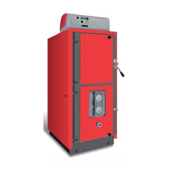
TECHNICAL FEATURES AND DIMENSIONS 2.1 - TECHNICAL FEATURES The heat generator mod. NOVAIREX is a steel boiler running with natural wooden logs, total gasification, inverted flame, with combustion chamber under negative pressure. It is supplied in the following models: NOVAIREX 34 NOVAIREX 45 NOVAIREX 55 The NOVAIREX boiler is complete with all the safety and control... -
Page 9: Dimensions And Plumbing Connections
2.2 - HYDRAULIC DIMENSIONS AND CONNECTIONS T7 - T8 1. Panel board T1. Central heating flow 2. Primary air adjustment T2. Central heating return 3. Secondary air adjustment T3. Safety thermostat probe bulb holder, boiler flow probe 4. Flame sight glass T4. -
Page 10: Technical Data
2.3 - TECHNICAL DATA NOVAIREX 34 NOVAIREX 45 NOVAIREX 55 MODELS (kW) MAXIMUM NOMINAL OUTPUT* 30.61 40.09 49.10 (kW) 34.2 45.05 55.16 FURNACE MAXIMUM OUTPUT 89.5 89.0 89.0 EFFICIENCY 4.73 5.05 6.12 13.9 13.74 13.6 (mg/Nm CO 10% (mg/Nm CO 13% (mg/Nm NOx 10% (mg/Nm... -
Page 11: Main Components
Unical has already used this principal for many years with the Therefore it is necessary to integrate it with a forced ventilation Gasogen boiler. - Page 12 NOVAIREX BOILER STRUCTURE The boiler body is composed of two oval elements placed one inside the other, so that a water cavity is created between the two. The large capacity wood storage has a special thermal and mechanical high resistance refractory press, for the purpose of keeping the by-pass area dry in all operating conditions.
- Page 13 REFRACTORY BURNER (4) The burner consists in a refractory stone (pos. 4.) This stone has a central rectangular opening that the flame passes through. The embers lie directly on the stone which divides the fire wood storage compartment from the lower combustion chamber. Furthermore the main refractory stone has a rectangular seat in which the suitably grooved thermal steel fire bars are placed (pos.
-
Page 14: Features Of The Wood
2.6 - WOOD CHARACTERISTICS DIMENSIONS Wood is formed mainly by cellulose and lignite. It also contains other substances, such as resin (fir - The dimensions, together with the moisture content, pine), tannin (oak - chestnut) and, obviously, a large contribute to determine the boiler’s output. Small quantity of water. -
Page 15: Instructions For The Installer
INSTRUCTIONS FOR INSTALLATION 3.1 - GENERAL WARNINGS b) Check that the chimney/flue has an appropri- ate draught, without any bottlenecks, and that no exhausts from other appliances are insert- ATTENTION! ed, unless the flue has been implemented to This boiler is intended solely for the use for accommodate several utilities according to which it was expressly designed. -
Page 16: Packaging
If the boiler is stored for long periods, it should sources of danger. be adequately protected. Unical will not be held liable for damage to per- sons, animals or objects due to failure to comply with the instruction above. Description of packs: 1. -
Page 17: Installation
3.6 - INSTALLATION NOVAIREX is a heat generator which withdraws the combustion To make it easier to clean, there must be a clearance space air required for the combustion process directly from the room in front of the heat stove no less than the length of the stove in which it is installed. -
Page 18: Connecting The Boiler To The System
3.7 - CONNECTING BOILER TO SYSTEM Attention! Make sure that there are no mechanical tension points while connecting the pipes to avoid the risk of leakage! Heating flow and return pipes must be connected to the boiler at the respective fittings as shown on page 6. For the dimensioning of the heating circuit pipes, you must take into account pressure drops caused by radiators, thermostatic valves, radiator stopping valves and by the configuration of the... - Page 19 3.8.1 - CONNECTION TO THE SAFETY HEAT EXCHANGER Solid fuel fired boilers must be installed with the safety devices foreseen by the relevant laws in force. For this purpose NOVAIREX boilers are equipped with a safety exchanger. A temperature relief valve must be installed on the safety heat exchanger by the installation technician, with control bulb set up inside the suitable sheath located on the rear of the NOVAIREX boiler.
- Page 20 It is always recommended to treat water with a hardness greater than 15°f. Unical has designed a "RECIRCULATION KIT FOR OPERATION WITH STORAGE TANK" for its customers. The kit is supplied as an option and is available by indicating the model of your boiler.
- Page 21 Insulation and casing assembly - Detail “A”: assemble the knob pos. 4 on the top door closing handle. Mount the screw and nut on the top door and screw the knob on (pos. 1, 2, 3). - Detail “B”: assemble the air header pos.
- Page 22 - Hook the left side panel onto the body of the boiler (pos. 1). - Hook the right side panel (pos. 2) onto the body of the boiler. - Put the panel board and the casing cover together (on the ground) (pos.
-
Page 23: Connection To The Flue
3.9 - CONNECTION TO THE FLUE To connect the flue gas exhaust pipe, local and national stand- can drain any condensation which may be formed); ards must be observed. Pipes must be built in such a way to guarantee maximum smoke tightness (UNI 10683);... - Page 24 3.9.1 - EXHAUST THROUGH EXTERNAL WALL weatherproof ter- minal. Draught limiter/adjuster Soot container with condensate drain One of the installation solutions which can be implemented is The flue gas exhaust pipe, if completely outside, should be made that of positioning NOVAIREX near a perimeter wall of the home in double wall stainless steel to guarantee both greater resistance so that flue gas is discharged directly outside.
- Page 25 3.9.2 - EXHAUST THROUGH ROOF BY MEANS OF TRADITIONAL FLUE Draught limiter/ adjuster Inspectionable soot container with possible condensate drain The pellet combustion flue gas can also be discharged using a It is recommended to provide a solid material and/or conden- traditional pre-existing flue as long it is made to standard (see sation collection chamber which can be inspected through an UNI 10683).
-
Page 26: Electrical Connections
Approvals the gas, water and heating systems are absolutely unsuitable The UNICAL panel board for NOVAIREX boilers has received as earthing electrodes. the EC approval according to standard EN 60335-1. -
Page 27: Connections
3.14 - CONNECTIONS Inverter Please note: Connection of the pump may change de- pending on the selected plumbing diagram. Comply with the connections set out in the diagrams. Termostato Manually di sicurezza reset safety a riarmo thermostat manuale Free contact Free auxiliary Heating Storage... -
Page 28: Reference Plumbing Diagrams
3.12 - HYDRAULIC BASE DIAGRAMS The following diagrams are for reference only and therefore are not binding. Unical declines any responsibility for errors or omissions. 3.12.1 - SYSTEM WITH NOVAIREX MODEL BOILER FOR HEATING USE In the following configuration the pump P2 is a recirculation... - Page 29 LIST OF PARAMETERS DEFAULT Parameter SETTINGS Boiler operating temperature Minimum boiler temperature for starting the circulating pumps Maximum boiler temperature for alarm Minimum auxiliary boiler temperature Auxiliary boiler operating temperature Temperature at which boiler starts being filled or storage tank heat. circulator start Temperature at which boiler stops being filled or storage tank DHW production end Maximum temperature for storage tank or solar protection storage tank Thermostat control thermal Delta for heating...
- Page 30 3.12.2 - NOVAIREX BOILER SYSTEM FOR HEATING AND FOR THE PRODUCTION OF DOMESTIC HOT WATER, WITH SINGLE-COIL TYPE STORAGE TANK In the following configuration pump P2 is a recirculation pump The fan stops when probe S4 reaches the temperature set in until the temperature detected by probe S4 does not meet the parameter P0.
- Page 31 LIST OF PARAMETERS DEFAULT Parameter SETTINGS Boiler operating temperature Minimum boiler temperature for starting the circulating pumps Maximum boiler temperature for alarm Minimum auxiliary boiler temperature Auxiliary boiler operating temperature Temperature at which boiler starts being filled or storage tank heat. circulator start Temperature at which boiler stops being filled or storage tank DHW production end Maximum temperature for storage tank or solar protection storage tank Thermostat control thermal Delta for heating...
- Page 32 3.12.3 - NOVAIREX BOILER SYSTEM FOR HEATING AND FOR THE PRODUCTION OF DOMESTIC HOT WATER, WITH TANK IN TANK TYPE STORAGE TANK In the following configuration pump P2 is in operation until the Pump P3 is on if S3 reaches the temperature set in parameter temperature detected by probe S4 meets the value set by pa- P5 and TA is in demand.
- Page 33 LIST OF PARAMETERS DEFAULT Parameter SETTINGS Boiler operating temperature Minimum boiler temperature for starting the circulating pumps Maximum boiler temperature for alarm Minimum auxiliary boiler temperature Auxiliary boiler operating temperature Temperature at which boiler starts being filled or storage tank heat. circulator start Temperature at which boiler stops being filled or storage tank DHW production end Maximum temperature for storage tank or solar protection storage tank Thermostat control thermal Delta for heating...
- Page 34 3.12.4 - NOVAIREX BOILER SYSTEM FOR HEATING AND FOR THE PRODUCTION OF DOMESTIC HOT WATER WITH TANK IN TANK STORAGE TANK AND BACK-UP BOILER (oil-fired) In the following configuration when the wood-fired boiler runs P3 switches on and an audible alarm will signal the overtem- out of loaded wood, if the automatic function has been selected perature.
- Page 35 LIST OF PARAMETERS DEFAULT Parameter SETTINGS Boiler operating temperature Minimum boiler temperature for starting the circulating pumps Maximum boiler temperature for alarm Minimum auxiliary boiler temperature Auxiliary boiler operating temperature Temperature at which boiler starts being filled or storage tank heat. circulator start Temperature at which boiler stops being filled or storage tank DHW production end Maximum temperature for storage tank or solar protection storage tank Thermostat control thermal Delta for heating...
- Page 36 3.12.5 - NOVAIREX BOILER SYSTEM FOR HEATING AND FOR THE PRODUCTION OF DOMESTIC HOT WATER WITH TANK IN TANK STORAGE TANK AND BACK-UP BOILER (wall-mounted) In the following configuration when the wood-fired boiler runs P3 switches on and an audible alarm will signal the overtem- out of loaded wood, if the automatic function has been selected perature.
- Page 37 LIST OF PARAMETERS DEFAULT Parameter SETTINGS Boiler operating temperature Minimum boiler temperature for starting the circulating pumps Maximum boiler temperature for alarm Minimum auxiliary boiler temperature Auxiliary boiler operating temperature Temperature at which boiler starts being filled or storage tank heat. circulator start Temperature at which boiler stops being filled or storage tank DHW production end Maximum temperature for storage tank or solar protection storage tank Thermostat control thermal Delta for heating...
- Page 38 3.12.6 - SOLAR SYSTEM MANAGEMENT To enable the solar system you must access parameter 17, as- The panel board of the Novairex boiler is able to control the sign value 1 to the probe (present). operation of solar panels in plumbing circuits where a storage The final value to be entered in parameter 17 is given by the tank or double coil storage tank is installed.
-
Page 39: Panel Board
3.13 - PANEL BOARD 3.13.1 - FRONT VIEW OF PANEL BOARD Functions of switches: Functions of indicator lights: Luminous main switch (green) solar panel pump start indicator light fan start key load pump start indicator light storage tank control unit RESET key heating pump start indicator light summer / winter key free indicator light... - Page 40 FUNCTIONS OF CONTROL SWITCHES / CONTROL KEYS: “MAINT” when a DHW or heating request is activated, and parameter “P 0” is met. Pressing the switch powers the panel and all the operations connected to it. The key silences the sound alarm in case of overtem- perature alarm.
- Page 41 3.13.2 - USE OF USER INTERFACE The front display of the board provides direct reading of the temperatures and operating status of the boiler; you may use the keyboard to scroll the screens to check the operating conditions according to the following wordings: 1 “Boiler Temp.”...
- Page 42 3.13.3 - GENERAL FEATURES AND STANDARD EQUIPMENT Microprocessor circuit board with alphanumerical four line BOARD SUPPLY: LCD display, keyboard and indicator lights indicating activa- The circuit board has the following inputs: tion of servomechanisms. general 230 Vac power supply input EPROM non-volatile memory (in case of a power outage, probe S1 input to measure solar panel temperature (J1 1-2) all previous settings remain valid).
- Page 43 3.13.4 - COMBUSTION POWER MODULATION The circuit board simultaneously performs two combustion For example, if parameter no. 0 (Boiler working temper- output modulations: ature) is set at 80°C and parameter no. 13 (Modulation Step) is set at 2 points, the fan speed will be decreased 1 Modulation of flue gas temperature by a total of 8 points.
- Page 44 3.13.5 - TECHNICAL PROGRAMMING MODE (ONLY QUALIFIED PERSONNEL): Programming procedure: PHASE 1 In order to enter functional parameter programming, PHASE 5 To edit other parameters, repeat the sequence scrolling with the direction arrows press and hold button for about 8 seconds, until “PROGRAMMING MODE”...
-
Page 45: Filling The System
This could damage the gaskets diators, radiant batteries and/or distribution and cause noise during operation. manifolds; Unical will not be held liable for damage to make sure that all the connections are water- persons, animals or objects due to failure to tight;... -
Page 46: Starting The Boiler
The preliminary checks must be carried out by the instal- Commissioning must be done by profession- lation fi rm. ally qualifi ed personnel. Unical will not be held liable for damage to persons, animals After connecting the hydraulic and electrical system and the fuel... - Page 47 3.15.2 - START-UP IGNITION Ensure the checks referred to in point 3.15.1 have been performed. Once the air has been adjusted in accordance with paragraph 3.15.3, close the bottom door and power the electric control board. The first ignition of the new boiler could be difficult due to moist refractory cement casting.
- Page 48 3.15.3 - COMBUSTION AIR ADJUSTMENT PRIMARY AND SECONDARY AIR ADJUSTMENT GENERAL ADVICE The NOVAIREX boiler is equipped with a combus- - Better performance will be achieved after two or three days tion air intake fan, a combustion air adjustment unit of running.
-
Page 49: Summer Operation
3.15.4 - CHECKS TO BE CARRIED OUT AFTER COMMISSIONING THE BYPASS CHECKING SEALS The bypass is a direct passage between the fire- wood storage compartment and the chimney. During the initial start-up, check the tightness of By opening the wood loading door, the by-pass the smoke circuit and connection to the chimney. -
Page 50: Troubleshooting
- Check if the doors are properly closed. Problem: If you cannot solve the problem, do no attempt any other interventions and contact an authorised UNICAL Af- - When opening the loading door there are blowbacks ter-Sales Service.. and smoke escape. -
Page 51: Alarm Diagram And Problem Solving
3.19 - ALARM AND PROBLEM SOLVING CHART Probe alarm signal: In case of failure or disconnection of one or more temperature probes, the control unit signals that they are missing indicating the number of the missing probe by a short beep of the buzzer. To eliminate the problem, check the con- nection of the probe and/or replace it. -
Page 52: Audible Alarms
3.20 - AUDIBLE ALARMS MAXIMUM TEMPERATURE PROBE AUDIBLE ALARM AUDIBLE ALARM The boiler has an intermittent alarm system that signals one or more faults with the probes due to these being disconnected or The boiler triggers an audible alarm when it is overheated. out of range;... -
Page 53: Inspection And Maintenance
Unical spare parts must be used. its long life. The appliance must be serviced according to... -
Page 54: Maintenance Of The Body
Boiler body maintenance CLEANING AND ROUTINE MAINTENANCE OF THE WOOD-FUELLED BOILER Danger! Before performing any maintenance on the Every day boiler, make sure the boiler and its compo- - Remove the ashes from the lower cradle. nents have cooled down. - Shake down, with the scraper supplied with the boiler, the embers so that the ashes, accumulated in the fire bed will fall down through the slots in the grate. - Page 56 S.p.A. info@unical-ag.com - export@unical-ag.com - www.unical.eu Unical shall not be held liable for any inaccuracies due to transcription or printing errors. Furthermore, it reserves the right to modify its products as deemed necessary or useful, without affecting their essential features.
Need help?
Do you have a question about the NOVAIREX Series and is the answer not in the manual?
Questions and answers