
Subscribe to Our Youtube Channel
Related Manuals for Unical NUA


Summary of Contents for Unical NUA
- Page 1 7 - 5 - 9 - 5 - 11 - 5 11 1C - 5 - 12 1C - 5 ISTRUZIONI PER L’INSTALLATORE E IL MANUTENTORE INSTALLATION AND MAINTENANCE INSTRUCTIONS...
- Page 2 PREMESSA Gentile Cliente, La ringraziamo per aver preferito uno dei nostri prodotti, frutto di lunga esperienza e di una continua ricerca per un prodotto superiore in termini di sicurezza, affidabilità e prestazioni. Perché lei possa ottenere le migliori prestazioni, le suggeriamo di leggere con attenzione le istruzioni contenute nel presente manuale.
-
Page 3: Table Of Contents
INFORMAZIONI GENERALI ................................... 4 1.1 - Avvertenze generali ...........................................4 1.2 - Riferimenti normativi ..........................................4 1.3 - Accessori in dotazione ........................................5 1.4 - Simbologia utilizzata nel manuale......................................5 1.5 - Avvertenze per la sicurezza .......................................6 1.5.1 - Sicurezze generalI ........................................6 1.5.2 - Sicurezze, avvertenze per l’installatore ................................9 1.5.3 - Sicurezze, avvertenze per il manutentore ................................10 CARATTERISTICHE TECNICHE E DIMENSIONI .......................... -
Page 4: Informazioni Generali
INFORMAZIONI GENERALI 1.1 - AVVERTENZE GENERALI 1.2 - RIFERIMENTI NORMATIVI Questo prodotto deve essere destinato all’uso per il quale è Norma UNI 10683: stato espressamente realizzato. Requisiti di installazione dei generatori di calore alimentati a E’ esclusa qualsiasi responsabilità contrattuale ed extracontrat- legna o altri biocombustibili solidi;... -
Page 5: Accessori In Dotazione
1.3 - ACCESSORI IN DOTAZIONE - Cavo alimentazione - Palmare - Mano fredda (maniglia) - Busta documenti 1.4 - SIMBOLOGIA UTILIZZATA NEL MANUALE Nella lettura di questo manuale, particolare attenzione deve essere posta alle parti contrassegnate dai simboli rappresentati: PERICOLO! ATTENZIONE! NOTA! Grave pericolo... -
Page 6: Avvertenze Per La Sicurezza
1.5 - AVVERTENZE PER LA SICUREZZA 1.5.1 - SICUREZZE GENERALI * L’apparecchio può essere utilizzato da bambini di età non inferiore a 8 anni e da persone con ridotte capacità fisiche, sensoriali o mentali, o prive di esperienza o della necessaria conoscenza, purché sotto sorveglianza oppure dopo che le stes- se abbiano ricevuto istruzioni relative all’uso sicuro dell’apparecchio e alla com- prensione dei pericoli ad esso inerenti. - Page 7 * Controllare la presenza di eventuali ostruzioni prima di accendere l’apparecchio in seguito ad un lungo periodo di mancato utilizzo. * Il generatore è stato progettato per autoregolarsi in condizioni particolari di funzio- namento. * Il generatore è stato progettato per funzionare con qualsiasi condizione climatica, in caso di condizioni particolarmente avverse (vento forte, gelo) potrebbero inter- venire sistemi di sicurezza che portano il generatore in spegnimento.
- Page 8 * Predisporre il luogo d’installazione della stufa secondo i regolamenti locali, nazio- nale ed europei vigenti nel luogo di installazione. * La stufa, essendo un prodotto da riscaldamento, presenta delle superfici esterne particolarmente calde. Per questo motivo si raccomanda la massima cautela du- rante il funzionamento in particolare: A) non toccare e non avvicinarsi al vetro della porta fuoco, potrebbe causare ustio- B) non toccare lo scarico dei fumi;...
-
Page 9: Sicurezze, Avvertenze Per L'installatore
È sempre consigliabile che gli utenti si rivolgano al servizio di POST VENDITA UNICAL per le richieste di tecnici qualificati. Nel caso intervengano altri tecnici si raccomanda di accertarsi sulle loro reali capacità. La responsabilità delle opere eseguite nello spazio d’ubicazione della stufa è, e rimane, a carico dell’utilizzatore;... -
Page 10: Sicurezze, Avvertenze Per Il Manutentore
A) non operare in condizioni avverse; B) deve operare in perfette condizioni psicofisiche e deve verificare che i dispositivi antinfortunistici individuali e personali, siano integri e perfettamente funzionanti; C) deve indossare i guanti antinfortunistici; D) deve indossare scarpe antinfortunistiche; E) deve usufruire di utensili muniti di isolamento elettrico; F) deve accertarsi che l’area interessata alle fasi di montaggio e di smontaggio sia libera da ostacoli. - Page 11 PAGINA LASCIATA VOLUTAMENTE BIANCA...
-
Page 12: Caratteristiche Tecniche E Dimensioni
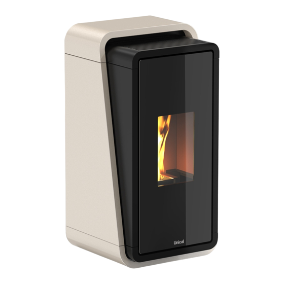
CARATTERISTICHE TECNICHE E DIMENSIONI 2.1 - CARATTERISTICHE TECNICHE Stufa a pellet rivestita in acciaio. Dotata di: Tradizionale sistema autopulente soffiato che garantisce un costante rendimento della combustione. Palmare Touch facile e intuitivo, per accedere a tutte le funzioni quali la regolazione della potenza, della tempera- tura, la programmazione settimanale fino ad un massimo di quattro programmi giornalieri indipendenti. - Page 13 Pos. Descrizione dim. PAm (Radiocomando con sonda ambiente) Console Uin-PLUS Termostato di sicurezza Connettore eBUS Alimentazione elettrica Messa a terra Canalizzazione aria (solo mod. C) Ø 60 Scarico fumi Ø 80 Presa aria Ø 50 Sportello caricamento pellet Maniglia apertura porta Vista posteriore Vista superiore 547 mm...
-
Page 14: Dati Tecnici
2.3 - DATI TECNICI MODELLI 7 - 5 9 - 5 11 - 5 11 1C - 5 ID Model 67010306_06 67010306_08 67010306_10 67010306_10C Unità di Funz. a Funz. a Funz. a Funz. a Funz. a Funz. a Funz. a Funz. - Page 15 MODELLI 12 1C - 5 67010306_11C ID Model Unità di Funz. a Funz. a misura P nom P min CONFORME ALLA NORMATIVA EN 14785: 2006 POTENZA TERMICA INTRODOTTA 12,1 POTENZA TERMICA NOMINALE 10,7 POTENZA TERMICA ALL’ARIA 10,7 POTENZA TERMICA ALL’ACQUA RENDIMENTO 88,2 94,5...
-
Page 16: Garanzia
Fabbricante nelle fasi di za Tecnica dislocati in tutto il territorio nazionale e riguarda i trasporto, movimentazione, stoccaggio, montaggio, instal- prodotti UNICAL nuovi, installati in Italia. lazione e regolazione dell’apparecchio; Essa non esclude, né limita i diritti derivanti dalla Direttiva - utilizzo dell’apparecchio per fini diversi da quelli a cui è... -
Page 17: Disimballo E Posizionamento
DISIMBALLO E POSIZIONAMENTO 3.2 - MOVIMENTAZIONE 3.1 - PREPARAZIONE E DISIMBALLO L’imballo è costituito da scatola in cartone ricicla- Nota: bile, pallet in legno. L indica anche il senso di inserimenti delle forche di sollevamento per movimentazione. Tutti i materiali di imballo possono essere riutiliz- zati per uso similare o eventualmente smaltibili come rifiuti assimilabili ai solidi urbani, nel rispetto delle norme vigenti. -
Page 18: Posizionamento
3.3 - POSIZIONAMENTO l piani di appoggio e/o punti di sostegno devono avere una capacità portante idonea a sopportare il peso complessivo dell’apparecchio, degli acces- sori e dei rivestimenti del medesimo. Si suggerisce che le pareti laterali, posteriori ed il piano di appoggio a pavimento siano in materiale non combustibile. -
Page 19: Distanze Minime Di Sicurezza Eintervento
3.4 - DISTANZE MINIME DI SICUREZZA E INTERVENTO E’ ammessa l’installazione in adiacenza a mate- Per i prodotti predisposti con distanziali posteriori è ammessa riali combustibili o sensibili al calore purché sia- l’installazione a filo muro esclusivamente per la parte poste- no interposte idonee distanze di sicurezza, vedi riore. -
Page 20: Combustibile
3.5 - COMBUSTIBILE Deve essere evitata la sua frantumazione e la formazione di segatura. Se viene immessa segatura nel serbatoio della stufa, questa 3.5.1 - CARATTERISTICHE DEL COMBUSTIBILE potrebbe causare il blocco del sistema di carica del pellet. L’utilizzo di pellet di qualità scadente può compromettere il nor- Il pellet è... -
Page 21: Installazione
N.B.: Gli apparecchi stagni si possono installare anche nei casi INSTALLAZIONE indicati dai punti 1, 2 ,3 del presente paragrafo. In bagni, camere da letto e monolocali è consentita esclu- sivamente l’installazione stagna o di apparecchi a foco- lare chiuso con prelievo canalizzato dell’aria comburente L’installazione deve essere eseguita da perso- dall’esterno. -
Page 22: Scarico Dei Fumi
4.4 - SCARICO DEI FUMI recchiature accese, la caduta di pressione tra la stanza e l’e- sterno non superi il valore di 4 Pa. Se necessario aumentare la sezione di ingresso della presa Il generatore di calore lavora in depressione ed è dotato di ven- d’aria, che deve essere realizzata ad una quota prossima al tilatore in uscita per l’estrazione fumi. - Page 23 TETTO A 30° MIN 1,30 metri DISTANZA > 1,50 metri DISTANZA < 1,50 metri 0,5 metri OLTRE IL COLMO 0,80 metri 30° ZONA DI REFLUSSO TETTO PIANO MIN 0,50 metri DISTANZA > 2 metri DISTANZA < 2 metri 0,5 metri VOLUME TECNICO 45°...
-
Page 24: Dimensionamento
4.5.2 - DIMENSIONAMENTO 4.5.5 - COMIGNOLO La depressione (tiraggio) di una canna fumaria dipende an- I comignoli devono soddisfare i requisiti seguenti: che dalla sua altezza. Verificare la depressione della canna avere sezione utile di uscita non minore del doppio di quella fumaria, la quale deve corrispondere con i valori indicati nelle del camino/sistema intubato sul quale è... -
Page 25: Installazione Ermetica
4.6 - INSTALLAZIONE ERMETICA 4.7 - SCHEMA ELETTRICO E COLLEGAMENTI I collegamenti elettrici, devono essere ese- L’installazione deve essere eseguita da per- guiti da personale qualificato e abilitato nel sonale qualificato e abilitato, il quale si assu- rispetto delle Norme vigenti nel paese di in- merà... -
Page 26: Schema Elettrico
4.8 - SCHEMA ELETTRICO 4.8.1 - SCHEMA CONNESSIONI ELETTRICHE ENCODER FUMI Termostato ambiente canalizzato on/off Sonda ambiente canalizzato opz. Sonda ambiente Contatto pulitura NON DISP. U-IN PLUS SANIFICATORE LUCI LED Pos. Descrizione Sicurezza: termostato a riarmo Sonda ambiente ntc Non disponibile Fumi Aspiratore fumi Term. -
Page 27: Note Per Il Corretto Funzionamento
4.9 - NOTE PER IL CORRETTO 4.10.2 - SICUREZZA SOVRAPRESSIONE IN CAMERA DI COMBUSTIONE FUNZIONAMENTO Eventuali e/o improvvise sovrapressioni dei fumi di combustio- Per un corretto funzionamento della stufa a pellet è necessario ne all’interno della camera di combustione vengono scaricati rispettare le seguenti indicazioni: attraverso l’apertura delle valvole di sicurezza poste sopra lo Sia durante il funzionamento della stufa, sia quando non viene... -
Page 28: Sicurezza Termostato Sovratemperatura Serbatoio Pellet
4.10.3 - SICUREZZA TERMOSTATO 4.10.4 - SICUREZZA ELETTRICA DI PROTEZIONE SOVRATEMPERATURA SERBATOIO DA SOVRACORRENTE PELLET L’apparecchio è protetto contro la sovracorrente da un fusibile da 3,15 A / 250V inserito sull’alimentazione dell’interruttore ge- Tra il serbatoio del pellet e la camera di combustione è posi- nerale della stufa dislocato posteriormente. -
Page 29: Uso
5.1 - RADIOCOMANDO PAM E CONSOLLE ‘‘U-In Plus’’ Per la gestione della stufa vengono forniti in dotazione degli strumenti di dialogo. Gli strumenti sono di diversa tipologia a seconda della configurazione della stufa stessa. Comunque in ogni configurazione è consentito agire sulle funzioni vitali per soddisfare le esigenze primarie di riscaldamento. -
Page 30: Consolle "U-In Plus
5.1.2 - CONSOLLE “U-In Plus” La Consolle “U-in PLUS” è collocata nella parte posteriore del- la stufa. Le sue funzioni sono: Consolle di emergenza in caso di guasto / inutilizzo del radiocomando WI-FI di serie per dialogo tra stufa e APP. Descrizione LED WI-FI: CONSOLLE/WI-FI “U-in PLUS”... -
Page 31: Display Radiocomando Caratteristiche E Funzioni
5.1.3 - DISPLAY RADIOCOMANDO 5.1.4 - DISPLAY RADIOCOMANDO ICONE E CARATTERISTICHE E FUNZIONI SCRITTE Il radiocomando è dotato di un display Lcd retro illuminato che per ridurre il consumo delle batterie si spegne (modalità rispar- mio energetico) dopo un determinato tempo. Funzione SET RETROILLUMINAZIONE: la durata della retro illuminazione è... -
Page 32: Gestione Stufa In Assenza Di Radiocomando
5.1.6 - GESTIONE STUFA IN ASSENZA DI 5.1.7 - RADIOCOMANDO PRECAUZIONI, RADIOCOMANDO CONSIGLI E POSIZIONAMENTO In caso di mancato funzionamento del radiocomando per: bat- Precauzioni e consigli: terie assenti o esauste, guasto, mancata connessione, interfe- • Nei lunghi periodi di inutilizzo si consiglia di rimuovere le renze con altre sorgenti IR;... -
Page 33: Menu' Generale (Utente)
5.2 - MENU’ GENERALE (UTENTE) 5.2.1 - DESCRIZIONE 5.2.2 - ELENCO SOTTOMENU’ La stufa è dotata di un Menù Generale Utente, a cui può ac- M01 REGOLA VENTOLE cedere anche l’utilizzatore, composto da una serie di funzioni se disponibile (a seconda dei modelli) (sotto menù) utili alla gestione della stufa e al confort di utilizzo. - Page 34 M02 SET OROLOGIO M03 SET CRONO La funzione consente di programmare l’accensione e lo spe- Il menù permette di impostare ora e data reale. Ora e data gnimento della stufa in modo automatico sulla base di orari sono mantenute da una batteria locata all’interno della sche- programmati.
- Page 35 segue M03 SET CRONO ATTENZIONE alle seguenti regole: • Prima di utilizzare il crono impostare DATE e ORA. • Per utilizzare il crono attivare sempre la funzione ABILITA CRONO. • Nei periodi di inutilizzo del CRONO è sufficiente disattivare la funzione ABILITA CRONO e comunque le programma- zioni impostate resteranno memorizzate.
- Page 36 M04 SCEGLI LINGUA M05 MODO STAND-BY Il menù permette di impostare la lingua più idonea all’utente Il menù permette di attivare o disattivare la funzione STAND- per la comunicazione sul display. La scelta va fatta tra quelle BY. Per attivare la funzione è sufficiente inserire il flag è con- disponibili.
- Page 37 FUNZIONE “STAND-BY” ATTIVATA COMANDATA DA M06 MODO CICALINO SONDA AMBIENTE Il menù permette di attivare o disattivare l’avvisatore acustico degli allarmi nel momento in cui si manifestano. Comunque Nella funzione Stand by attivata, se la sonda ambiente rile- gli allarmi sono sempre visibili sullo stato del display. Dopo va la stessa temperatura impostata di SET, la stufa si porta aver attivato o meno la funzione è...
- Page 38 M08 STATO STUFA M09 TARATURE TECNICO E’ una funzione riservata al TECNICO AUTORIZZATO. E’ un menù riservato al TECNICO AUTORIZZATO. Nel menù sono presenti i valori più importanti forniti dai se- ATTENZIONE: gnali reali di Ingresso e uscita della scheda elettronica visua- la modifica dei parametri tecnici sul menu 09 lizzati in tempo reale.
-
Page 39: Prima Accensione
5.3 - PRIMA ACCENSIONE 5.3.1 - AVVERTENZE E CONSIGLI 5.3.2 - CONTROLLI PREVENTIVI da effettuare ad ogni accensione L’Azienda fornisce una serie di Consigli da seguire durante le prime accensioni del prodotto: Prima di procedere con l’accensione del prodotto è necessario effettuare una serie di controlli: •... -
Page 40: Impostazioni Prima Accensione
5.3.3 - IMPOSTAZIONI PRIMA ACCENSIONE Una volta collegato il cavo di alimentazione nella parte poste- STAND-BY (M05 MODO STAND-BY) riore del generatore, portare l’interruttore (se presente), nella posizione (I). Con l’impostazione di fabbrica al raggiungimento della tempe- ratura ambiente la stufa modula a potenza 1 per mantenere L’interruttore serve per dare tensione alla scheda del gene- l’ambiente in temperatura (la durata per il mantenimento dipen- ratore. - Page 41 CONFIGURAZIONI: di seguito vengono descritte le configura- zioni disponibili a seconda del dispositivo installato. 1) TERMOSTATO AMBIENTE CANALIZZATO on/off. • Installare, nell’ambiente riscaldato dalla canalizzazione, un comune termostato ambiente con contatto pulito on/off e collegare i fili nell’ingresso dedicato in scheda. •...
-
Page 42: Accensione E Logica
5.3.4 - ACCENSIONE E LOGICA RIACCENSIONE La riaccensione della stufa è possibile solo se la temperatura ACCENSIONE + PRERISCALDO fumi è inferiore ad una soglia prefissata e se è trascorso un Una volta verificati i punti in precedenza elencati, procedere tempo minimo di sicurezza dall’inizio del processo di spegni- con l’accensione agendo sul tasto (5) del radiocomando tenen- mento. -
Page 43: Sanificazione Dell'aria (Opzionale)
5.5 - SANIFICAZIONE DELL’ARIA (OPZIONALE) 5.6 - SANIFICATORE ARIA AMBIENTE (OPZ.) La stufa puo’ essere dotata di un sistema di sanitizzazione integrato e posizionato nel lato posteriore. Si tratta di un dispositivo di sanificazione e purificazione dell’a- ria e delle superfici attraverso la riduzione microbica presente nell’ambiente. - Page 44 done il funzionamento (Fig. 6). ANOMALIE E GUASTI: in caso di mancato funzionamento eseguire le seguenti verifiche. Il led non si accende: verificare che la stufa sia alimentata elettricamente, che l’interruttore generale sia in posizione 1 e che il fusibile non sia guasto. Il led non si accende: verificare che il pulsante di accensio- ne del sanificatore sia premuto.
-
Page 45: Ispezione E Manutenzione
ISPEZIONE E MANUTENZIONE 6.1 - MANUTENZIONE 6.2 - PULIZIA ORDINARIA A CARICO DELL’UTILIZZATORE Le operazioni periodiche di controllo e le manu- tenzioni devono essere sempre eseguite da tec- Le operazioni di pulizia ordinaria, come indicato nel presente nici specializzati, abilitati che operano secondo la manuale uso e manutenzione, devono essere eseguite pre- normativa vigente nel paese di installazione del stando la massima cura dopo aver letto le indicazioni, le proce-... -
Page 46: Vano Raccolta Cenere
Riposizionare il braciere nella sua sede e spingerlo verso Un braciere pulito garantisce un corretto fun- la parete focolare. zionamento! Mantenendo il braciere e i suoi fori sempre Le pareti laterali e posteriori, in alcuni prodotti sono com- ben puliti da eventuali residui di combustione, poste da materiale fragile che dopo la prima combustione si garantisce al generatore un’ottima combu- si compatta e si irrigidisce agli urti e per tale motivo non... -
Page 47: Pulizia Straordinaria Eseguita Da Tecnico Abilitato
TABELLA INDICATIVA DELLE OPERAZIONI DI PULIZIA ORDINARIA A CARICO DELL’UTENTE Parti / Periodo Manutentore Ogni Giorno 2-3 Giorni 1 Mese 2 Mesi 1 Anno Ogni Segnale Service Ordinario Ordinario Ordinario Ordinario Straordinario Braciere Utente Vano cassetto cenere Utente Vetro Utente Pareti camera di com- bustione e deviatore Utente... -
Page 48: Messa Fuori Servizio (Fine Stagione)
TABELLA INDICATIVA DELLE OPERAZIONI DI MANUTENZIONE STRAORDINARIA TECNICO ABILITATO Parti / Periodo Manutentore Ogni Giorno 2-3 Giorni 1 Mese 2 Mesi 1 Anno Ogni Segnale Service Ordinario Ordinario Ordinario Ordinario Straordinario Utente Raccordo “T” Tecnico Scambiatore termico e Tecnico vano ispezione Guarnizioni: porta, Tecnico vetro e scambiatore... -
Page 49: Allarmi, Anomalie E Soluzioni
6.5 - ALLARMI, ANOMALIE E SOLUZIONI In caso di anomalia operare secondo le istru- Le anomalie causate dalla inefficiente o mancata manuten- zione o dalla inosservanza delle indicazioni del manuale zioni riportate sul seguente manuale d’uso. Tutte le operazioni di ripristino e verifica devo- di installazione ed uso del prodotto, fanno decadere le re- no essere effettuate esclusivamente ad appa- sponsabilità... - Page 50 Verificare che la resistenza scaldi (contattare un tecnico autorizzato). Verificare se il sistema di carico pellet funziona (contat- tare un tecnico autorizzato) Verificare la presenza di pellet all’interno del serbatoio ALLARME 5 Si verifica nella fase di accensione se e quindi nel braciere. Eventualmente portare la stufa in i fumi di scarico non raggiungono la Off e ripetere le procedure di accensione assicurandosi MANCATA ACCENSIONE...
-
Page 51: Tabella Anomalie E Soluzioni
Il sistema di scarico dei fumi potrebbe essere ostruito o non lavorare correttamente. Verificare e pulire l’intero sistema di scarico fumi (contattare la ditta installatrice). Verificare che il sistema di scarico dei fumi rispetti la norma vigente nel paese di installazione. Verificare che lo sportello serbatoio pellet sia chiuso correttamente oppure non sia rimasto aperto per oltre 30 secondi durante la fase di caricamento pellet. - Page 52 Verificare se sia stato predisposto un regolare sistema antivento. Il vento inoltre entra in canna fumaria perché non protetta o perché è stata eseguita un’installazione senza canna fumaria o a parete. Si ricorda il rispetto del tiraggio raccomandato per il corretto funzionamento dei prodotti (come previsto da scheda tecnica contenuta all’interno del manuale Dopo la prima accensio-...
- Page 53 Il pellet è umido, di scarsa qualità oppure di taglia e dimensione molto Sostituire il pellet con uno certificato e asciutto. piccola. Verificare che la presa d'aria in ambiente sia presente Il prodotto si arresta da e libera. Verificare che il braciere sia correttamente solo durante il funziona- posizionato nella propria sede e controllare che tutti i mento.
-
Page 54: Avvertenze Per Il Corretto Smaltimento Del Prodotto
6.6 - AVVERTENZE PER IL CORRETTO SMALTIMENTO DEL PRODOTTO tive per I’ambiente e per la salute, derivanti da un suo smalti- La demolizione e lo smaltimento della stufa sono mento inadeguato, e permette di recuperare i materiali di cui è ad esclusivo carico e responsabilità... - Page 55 C. RIVESTIMENTO INTERNO E. STRUTTURA METALLICA Se presente smaltire separatamente secondo il materiale Smaltire separatamente nel metallo che lo compone: F. COMPONENTI NON RICICLABILI Metallo Materiali refrattari Es: Guarnizioni, tubazioni in gomma, silicone o fibre, plasti- Pannelli isolanti che. Smaltire nei rifiuti misti Vermiculite Materiali refrattari, pannelli isolanti, vermiculite entrati G.
- Page 56 FOREWORD Dear Customer, Thank you for having chosen one of our products, the result of long experience and of an ongoing quest for a superior product in terms of safety, reliability and performance. In order for you to achieve the best performance, we recommend that you read the instructions in this manual carefully.
- Page 57 GENERAL INFORMATION ..................................4 1.1 - General warnings ..........................................4 1.2 - Normative references.........................................4 1.3 - Supplied accessories .........................................5 1.4 - Symbols used in the manual ......................................5 1.5 - Safety warnings ..........................................6 1.5.1 - General safety measures .....................................6 1.5.2 - Safety measures, warnings for the installer ................................9 1.5.3 - Safety measures, warnings for the maintenance engineer ..........................10 TECHNICAL CHARACTERISTICS AND DIMENSIONS ........................
-
Page 58: General Information
GENERAL INFORMATION 1.1 - GENERAL WARNINGS 1.2 - NORMATIVE REFERENCES This product must be intended for the use for which it was Standard UNI 10683: expressly made. Installation requirements for heat generators fuelled by wood The manufacturer will have no contractual or extra-contractual or other solid biofuels;... -
Page 59: Supplied Accessories
1.3 - SUPPLIED ACCESSORIES - Power cable - Handheld console - Cold handle - Document envelope 1.4 - SYMBOLS USED IN THE MANUAL When reading this manual, pay special attention to the parts marked by the symbols shown: DANGER! ATTENTION! NOTE! Serious danger Possible dangerous... -
Page 60: Safety Warnings
1.5 - SAFETY WARNINGS 1.5.1 - GENERAL SAFETY MEASURES * The appliance may be used by children of at least 8 years of age and by persons with reduced physical, sensory or mental capabilities, or lack of experience or the necessary knowledge, provided that they are supervised or have received instruc- tions concerning the safe use of the appliance and understanding of the dangers involved. - Page 61 * Check for obstructions before switching on the appliance after a long period of non-use. * The generator is designed to self-regulate under particular operating conditions. * The generator is designed to operate in all weather conditions; in the event of par- ticularly adverse conditions (strong wind, frost), safety systems may trip and shut down the generator.
- Page 62 * Prepare the stove installation site in accordance with the local, national and Euro- pean regulations in force at the installation site. * As the stove is a heating appliance, its outer surfaces are especially hot. For this reason the utmost caution is recommended during operation, namely: A) do not touch or approach the glass of the fire door, it could cause burns;...
-
Page 63: Safety Measures, Warnings For The Installer
Instructions on the assembly and disassembly of the stove are for specialist tech- nicians only. It is always advisable for users to contact the UNICAL AFTER-SALES service for requests for qualified technicians. Should other technicians intervene, it is recom- mended to ascertain their actual capabilities. -
Page 64: Safety Measures, Warnings For The Maintenance Engineer
A) not to operate in adverse conditions; B) must work in perfect psychophysical condition and must check that individual and personal accident prevention equipment is intact and fully functional; C) must wear safety gloves; D) must wear safety shoes; E) must use electrically insulated tools; F) must ensure that the area involved in assembly and disassembly is free of ob- stacles. - Page 65 PAGE INTENTIONALLY LEFT BLANK...
-
Page 66: Technical Characteristics And Dimensions
TECHNICAL CHARACTERISTICS AND DIMENSIONS 2.1 - TECHNICAL FEATURES Steel-clad pellet stove. Equipped with: Traditional blown self-cleaning system that guarantees constant combustion efficiency. Easy and intuitive Touch console, to access all functions such as power and temperature control, weekly pro- gramming up to a maximum of four independent daily programmes. - Page 67 Pos. Description dim. PAm (Radio control with room probe) Uin-PLUS console Safety thermostat eBUS connector Electrical power supply Earthing Air ducting (only mod. C) Ø 60 Flue gas exhaust Ø 80 Air intake Ø 50 Pellet loading door Door opening handle Rear view Top view 547 mm...
-
Page 68: Technical Data
2.3 - TECHNICAL DATA MODELS 7 - 5 9 - 5 11 - 5 11 1C - 5 ID Model 67010306_06 67010306_08 67010306_10 67010306_10C Unit of meas- Func. at Func. at Func. at Func. at Func. at Func. at Func. at Func. - Page 69 MODELS 12 1C - 5 67010306_11C ID Model Unit of meas- Func. at Func. at urement P nom P min COMPLIANT WITH STANDARD EN 14785: 2006 HEAT OUTPUT INTRODUCED 12.1 NOMINAL HEAT OUTPUT 10,7 AIR HEAT OUTPUT 10,7 WATER HEAT OUTPUT EFFICIENCY 88,2 94,5...
-
Page 70: Warranty
- wilful or culpable conduct attributable to a vendor or other manufacturer through its network of Technical Assistance person unrelated to the manufacturer during transport, Centres located throughout Italy and concerns new UNICAL handling, storage, assembly, installation and adjustment products installed in Italy. -
Page 71: Unpacking And Positioning
UNPACKING AND POSITIONING 3.1 - PREPARATION AND UNPACKING 3.2 - HANDLING Packaging consists of recyclable cardboard box, Note: wooden pallet. L also indicates the direction of insertion of the lifting forks for handling. All packaging materials can be reused for simi- lar use or possibly disposed of as municipal solid waste, in accordance with the regulations in force. -
Page 72: Positioning
3.3 - POSITIONING The support surfaces and/or points must have a load-bearing capacity to support the total weight of the appliance, its accessories and coverings. It is suggested that the side and rear walls and the floor support surface be made of non-combustible material. -
Page 73: Minimum Safety Distances And Intervention
3.4 - MINIMUM SAFETY DISTANCES AND INTERVENTION Installation adjacent to combustible or heat-sensi- The product must be installed in a location that allows safe and tive materials is permissible provided that suitable easy operation and maintenance. safety distances are interposed, see drawing This place must also be equipped with an electrical system with earthing as required by current standards. -
Page 74: Fuel
3.5 - FUEL The use of poor-quality pellets may impair the normal operation of the pellet stove and lead to the voiding of the warranty. 3.5.1 - FUEL CHARACTERISTICS 3.5.3 - PELLET LOAD Pellets are a compound consisting of various types of wood The stove is equipped with a pellet holding hopper of the ca- pressed using mechanical processes in compliance with envi- pacity indicated in the table of characteristic data in the Use... -
Page 75: Installation
N.B.: Airtight appliances can also be installed in the cases indi- INSTALLATION cated in points 1, 2, 3 of this paragraph. In bathrooms, bedrooms and one-room apartments, only airtight or closed fireplace appliances with ducted combus- tion air intake from outside are permitted. Installation must be performed by skilled and qualified personnel, who shall be entirely respon- sible for final installation and consequent proper... -
Page 76: Smoke Exhaust
4.4 - SMOKE EXHAUST If necessary, increase the inlet cross-section of the air intake, which must be built at a height close to the floor and always protected with an external bird-proof grate and in such a way The heat generator works under negative pressure and is that it cannot be obstructed by any object. - Page 77 30° ROOF MIN 1.30 metres DISTANCE > 1.50 metres DISTANCE < 1.50 metres 0.5 metres ABOVE THE ROOF RIDGE 30° 0.80 metres REFLUX ZONE FLAT ROOF MIN 0.50 metres DISTANCE > 2 metres DISTANCE < 2 metres 0.5 metres TECHNICAL VOLUME 45°...
-
Page 78: Dimensioning
4.5.2 - DIMENSIONING 4.5.5 - CHIMNEY The negative pressure (draught) of a chimney also depends on Chimneys must meet the following requirements: its height. Check the negative pressure in the chimney, which have a useful outlet cross-section not less than twice that of must correspond with the values given in the technical charac- the chimney/piped system on which it is inserted;... -
Page 79: Hermetic Installation
4.6 - HERMETIC INSTALLATION 4.7 - WIRING DIAGRAM AND CONNECTIONS Installation must be performed by skilled per- Electrical connections must be carried out by sonnel, who shall be entirely responsible for qualified and authorised personnel in compli- final installation and consequent proper oper- ance with the regulations in force in the coun- ation of the installed product. -
Page 80: Wiring Diagram
4.8 - WIRING DIAGRAM 4.8.1 - ELECTRICAL CONNECTION DIAGRAM FLUE GAS ENCODER Ducted room thermostat on/off Optional ducted room probe NTC room probe Cleaning contact NOT AVAIL. U-IN PLUS SANITIZER LED LIGHTS Pos. Description Safety: reset thermostat Ntc room probe Not available Flue gas Smoke extractor... -
Page 81: Notes For Proper Functioning
4.9 - NOTES FOR PROPER 4.10.2 - OVERPRESSURE SAFETY IN COMBUSTION CHAMBER FUNCTIONING Any and/or sudden overpressure of the combustion fumes in- For the pellet stove to function properly, the following instruc- side the combustion chamber is discharged through the open- tions must be observed: ing of the safety valves located above the heat exchanger. -
Page 82: Pellet Hopper Over-Temperature Thermostat Safety Device
4.10.3 - PELLET HOPPER OVER-TEMPERATURE 4.10.4 - ELECTRICAL OVERCURRENT THERMOSTAT SAFETY DEVICE PROTECTION There is a temperature probe between the pellet hopper and The stove is protected against overcurrent by a 3.15 A / 250V the combustion chamber connected to a manually reset safety fuse on the power supply of the stove's main switch located at thermostat which automatically deactivates the pellet supply in the rear. -
Page 83: Use
5.1 - PAM RADIO CONTROL AND CONSOLE ‘‘U-In Plus’’ Dialogue tools are provided for operating the stove. The instru- ments are of different types depending on the configuration of the stove itself. In any configuration, however, it is permissible to act on vital functions to meet primary heating needs. 5.1.1 - PAM RADIO CONTROL Thanks to the radio control, it is possible to adjust the main functions of the stove and make use of some of the functions... -
Page 84: U-In Plus" Console
5.1.2 - “U-In Plus” CONSOLE The 'U-in PLUS' console is located at the rear of the stove. Its functions are: Emergency console in case of failure/non-use of radio control WI-FI as standard for dialogue between stove and APP. Description WI-FI LED: “U-in PLUS”... -
Page 85: Radio Control Display Features And Functions
5.1.3 - RADIO CONTROL DISPLAY FEATURES 5.1.4 - RADIO CONTROL DISPLAY ICONS AND AND FUNCTIONS TEXTS The radio control is equipped with a backlit LCD display which, in order to reduce battery consumption, switches off (pow- er-saving mode) after a certain time. BACKLIGHT SET function: the duration of backlighting is 10 seconds (adjustable) from the last press of any button. -
Page 86: Stove Management In The Absence Of Radio Control
5.1.6 - STOVE MANAGEMENT IN THE ABSENCE 5.1.7 - RADIO CONTROL PRECAUTIONS, TIPS OF RADIO CONTROL AND POSITIONING In the event of failure of the radio control due to: missing or Precautions and tips: dead batteries, fault, no connection, interference with other IR •... -
Page 87: General (User) Menu
5.2 - GENERAL (USER) MENU 5.2.1 - DESCRIPTION 5.2.2 - SUBMENU LIST The stove is equipped with a General User Menu, which can M01 ADJUST FANS also be accessed by the user, comprising a series of functions if available (depending on model) (sub-menus) useful for stove management and operating com- The menu allows you to set the speed of the hot air fan mo- fort. - Page 88 M02 CLOCK SETTING M03 PROGRAMMER SETTING This function allows the stove to be programmed to switch on The menu allows you to set the actual time and date. Time and off automatically on the basis of programmed times. By and date are maintained by a battery located inside the cir- default, the PROGRAMMER is deactivated.
- Page 89 continued M03 PROGRAMMER SETTING PAY ATTENTION to the following rules: • Before using the programmer set DATE and TIME. • To use the programmer always activate the ENABLE PRO- GRAMMER function. • During periods when the PROGRAMMER is not in use, simply deactivate the ENABLE PROGRAMMER function and the set programming will still be stored.
- Page 90 M04 CHOOSE LANGUAGE M05 STAND-BY MODE The menu allows the user to set the most suitable language The menu allows the STAND-BY function to be activated or for communication on the display. The choice must be made deactivated. To activate the function, simply enter the flag among those available.
- Page 91 STAND-BY FUNCTION ACTIVATED BY ROOM PROBE M06 BUZZER MODE The menu allows you to activate or deactivate the alarm When the stand-by function is activated, if the room probe buzzer as they are triggered. However, alarms are always detects the same temperature as SET, the stove switches visible on the display status.
- Page 92 M08 STOVE STATUS M09 TECHNICAL SETTINGS This function is reserved for the AUTHORISED TECHNI- It is a menu reserved for the AUTHORISED TECHNICIAN. CIAN. The menu contains the most important values provided by ATTENTION: the actual input and output signals of the circuit board dis- Modification of technical parameters on the 09 played in real time.
-
Page 93: Commissioning
5.3 - COMMISSIONING 5.3.1 - RECOMMENDATIONS AND TIPS 5.3.2 - PREVENTIVE CHECKS to be carried out at each ignition The company provides a series of tips to be followed during the first ignition of the product: Before switching on the product, a number of checks must be carried out: •... -
Page 94: Commissioning Settings
5.3.3 - COMMISSIONING SETTINGS Once the power cable is connected at the rear of the generator, STAND-BY (M05 STAND-BY MODE) turn the switch (if fitted) to position (I). With the default setting, when the room temperature is reached The switch is used to energize the generator board. The dis- the stove modulates to power 1 to keep the room at tempera- play of the product shows the word OFF to represent the initial ture (the duration for holding depends on the insulation class... - Page 95 CONFIGURATIONS: the configurations available depending on the device installed are described below. 1) DUCTED ROOM THERMOSTAT on/off. • Install, in the room heated by the ducting, a common room thermostat with potential-free contact on/off and connect the wires to the dedicated input on the board. •...
-
Page 96: Ignition And Logic
5.3.4 - IGNITION AND LOGIC RE-IGNITION Re-ignition of the stove is only possible if the flue gas tempera- IGNITION + PREHEATING ture is below a preset threshold and a minimum safety time has Once the points listed above have been checked, proceed with elapsed since the start of the extinction process. -
Page 97: Air Sanitisation (Optional)
5.5 - AIR SANITISATION (OPTIONAL) 5.6 - ROOM AIR SANITISER (OPTIONAL) The stove can be equipped with an integrated sanitisation system located at the rear. It is a device for sanitising and purifying air and surfaces through microbial reduction in the environment. OPERATING PRINCIPLE: it is based on a bipolar ionisation process which, through the activation of oxygen molecules, produces a sanitising, antibacterial action, purifying the air... - Page 98 TROUBLESHOOTING: in the event of a malfunction, carry out the following checks. The LED does not light up: check that the stove is electri- cally powered, that the main switch is in position 1 and that the fuse is not blown. The LED does not light up: check that the sanitiser power button is pressed.
-
Page 99: Inspection And Maintenance
INSPECTION AND MAINTENANCE 6.1 - MAINTENANCE 6.2 - ROUTINE CLEANING CARRIED OUT BY THE USER Periodic inspection and maintenance operations must always be carried out by specialised, au- Routine cleaning operations, as set out in this operation and thorised technicians working in accordance with maintenance manual, must be carried out with the utmost care the regulations in force in the country where the after reading the instructions, procedures and timetables de-... -
Page 100: Ash Collection Compartment
Put the brazier back in place and push it towards the fire- A clean brazier guarantees proper function- box wall. ing! By keeping the brazier and its holes always The side and rear walls in some products are made of well clear of any combustion residue, the gen- brittle material that compacts and stiffens due to shocks erator is guaranteed optimal combustion over... -
Page 101: Extraordinary Cleaning Carried Out By A Qualified Technician
INDICATIVE TABLE OF ROUTINE CLEANING OPERATIONS TO BE CARRIED OUT BY THE USER Parts / Period Maintenance Every Day 2-3 Days 1 Month 2 Months 1 Year Each Signal engineer Service Routine Routine Routine Routine Extraordinary Brazier User Ash pan compartment User Glass User... -
Page 102: Decommissioning
INDICATIVE TABLE OF EXTRAORDINARY MAINTENANCE OPERATIONS CERTIFIED TECHNICIAN Parts / Period Maintenance Every Day 2-3 Days 1 Month 2 Months 1 Year engineer Each Service Signal Routine Routine Routine Routine Extraordinary User Tee fitting Technician Heat exchanger and inspection compart- Technician ment Gaskets: door, glass... -
Page 103: Troubleshooting
6.5 - TROUBLESHOOTING In the event of a fault, operate according to the Faults caused by inefficient or lack of maintenance or non-compliance with the instructions in the product's in- instructions in the following manual. All reset and checks must be carried out only stallation and operating manual will invalidate the manu- when the appliance is cold, in the complete facturer's liability. - Page 104 Check that the resistor heats up (contact an authorised technician). Check whether the pellet loading system works (contact an authorised technician) Check the presence of pellets inside the hopper and ALARM 5 This alarm triggers in the ignition phase thus in the brazier. If necessary, turn the stove Off and if the flue gas does not reach the ap- repeat the ignition procedures, ensuring that the brazier FAILED IGNITION...
- Page 105 The flue gas exhaust system may be obstructed or not working properly. Check and clean the entire flue gas exhaust system (contact the installation company). Check that the flue gas exhaust system complies with the standard in force in the country of installation. Check that the pellet hopper door is closed properly or has not been open for more than 30 seconds during pellet loading.
- Page 106 Check whether a regular wind protection system is in place. Wind also enters the chimney because it is un- protected or because an installation has been carried out without a chimney or wall. Please remember to respect the recommended draught for the correct operation of the products (as set out in the technical data sheet contained in the use and mainte- Installation and fuel...
- Page 107 The pellets are either moist, of poor quality or very small in size and dimen- Replace the pellets with certified, dry ones. sion. Ensure the air intake in the room is present and free. The product stops abruptly Check that the brazier is correctly positioned in its seat during operation.
-
Page 108: Recommendations For The Correct Disposal Of The Product
6.6 - RECOMMENDATIONS FOR THE CORRECT DISPOSAL OF THE PRODUCT health, resulting from its inappropriate disposal, can be avoid- ed, and the materials from which it is made can be recovered The demolition and disposal of the stove is the in order to achieve significant savings in energy and resources. - Page 109 C. INNER CLADDING F. NON-RECYCLABLE COMPONENTS If present, dispose of separately according to the material: E.g.: Gaskets, rubber, silicone or fibre hoses, plastics. Dis- pose of with mixed waste Metal Refractory materials G. HYDRAULIC COMPONENTS Insulating panels Vermiculite Pipes, fittings, expansion vessel, valves. Refractory materials, insulating panels, vermiculite that If present, dispose of them separately according to their have come into contact with flame or exhaust gases...
- Page 112 - export@unical-ag.com - www.unical.eu Unical declina ogni responsabilità per le possibili inesattezze se dovute ad errori di trascrizione o di stampa. Si riserva altresì il diritto di apportare ai propri prodotti quelle modifiche che riterrà necessarie o utili, senza pregiudicarne le caratteristiche essenziali.
Need help?
Do you have a question about the NUA and is the answer not in the manual?
Questions and answers