
Related Manuals for Daikin FH26NUV14


Summary of Contents for Daikin FH26NUV14
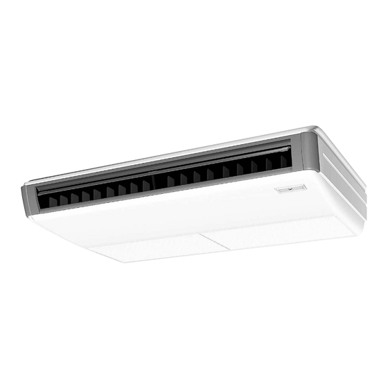
- Page 1 Si241304 REMOVAL PROCEDURE S E R V I C E M A N U A L 2.5/3/4/5/6 HP Class Indoor Unit Non-Inverter Ceiling Suspended Type...
- Page 2 Service Manual Removal Procedure Indoor Unit Indoor Models Cooling Only FH21NUV14 FH26NUV14 FH36NUV14 FH42NUV14 FH48NUV14 FH36NUV2S FH42NUV2S FH48NUV2S...
-
Page 3: Table Of Contents
Si241304 Table of Contents 1. Procedure to Remove Air Filter and Suction Grille .........2 2. Procedure to Remove Electrical Parts and PCB........3 3. Procedure to Remove Horizontal Blade..........5 4. Procedure to Remove Fan Rotor and Motor ...........6 5. Procedure to Remove Fan Bearing............8 6. -
Page 4: Procedure To Remove Air Filter And Suction Grille
Procedure to Remove Air Filter and Suction Grille Si241304 1. Procedure to Remove Air Filter and Suction Grille Procedure Warning Be sure to wait for 10 minutes or more after turning off all power supplies before disassembling work. Procedure Points Step Press the 2 tabs and open the suction grilles. -
Page 5: Procedure To Remove Electrical Parts And Pcb
Si241304 Procedure to Remove Electrical Parts and PCB 2. Procedure to Remove Electrical Parts and PCB Procedure Warning Be sure to wait for 10 minutes or more after turning off all power supplies before disassembling work. Procedure Points Step Loosen the 2 screws of the control box cover and remove the control box cover. - Page 6 Procedure to Remove Electrical Parts and PCB Si241304 Step Procedure Points Disconnect all connector mounted on the PCB. Remove the PCB installation screw. (4 Point) Removal Procedure...
-
Page 7: Procedure To Remove Horizontal Blade
Si241304 Procedure to Remove Horizontal Blade 3. Procedure to Remove Horizontal Blade Procedure Warning Be sure to wait for 10 minutes or more after turning off all power supplies before disassembling work. Procedure Points Step Gently bend the support plate located at the center of the horizontal blade, and detach the center shaft. -
Page 8: Procedure To Remove Fan Rotor And Motor
Procedure to Remove Fan Rotor and Motor Si241304 4. Procedure to Remove Fan Rotor and Motor Procedure Warning Be sure to wait for 10 minutes or more after turning off all power supplies before disassembling work. Procedure Points Step Press the 2 tabs of the fan housing toward the inside with your fingers, and pull out the fan... - Page 9 Si241304 Procedure to Remove Fan Rotor and Motor Step Procedure Points Slide the intermediate bearing to the right and remove the fan rotor assy. Remove the 2 fan motor fasteners. ∗ Finally reconnect the fan Remove the fan motor. motor connector, cover it with the glass tube and secure it with the tie-wrap.
-
Page 10: Procedure To Remove Fan Bearing
Procedure to Remove Fan Bearing Si241304 5. Procedure to Remove Fan Bearing Procedure Warning Be sure to wait for 10 minutes or more after turning off all power supplies before disassembling work. Procedure Points Step ∗ Remove the fan rotor according to the procedures to remove the fan rotor and fan motor. -
Page 11: Procedure To Remove Bottom Panel And Drain Pan
Si241304 Procedure to Remove Bottom Panel and Drain Pan 6. Procedure to Remove Bottom Panel and Drain Procedure Warning Be sure to wait for 10 minutes or more after turning off all power supplies before disassembling work. Step Procedure Points Remove the 7 bottom panel installation screws (2 each on the... -
Page 12: Procedure To Remove Swing Motor
Procedure to Remove Swing Motor Si241304 7. Procedure to Remove Swing Motor Procedure Warning Be sure to wait for 10 minutes or more after turning off all power supplies before disassembling work Procedure Points Step Remove the screw from the right side panel. Slide the right side panel toward the front and detach it. - Page 13 Revision History Month / Year Version Revised contents 01/2013 Si241304 First edition...
- Page 14 Improper installation can result in water or refrigerant leakage, electrical shock, fire or explosion. Use only those parts and accessories supplied or specified by Daikin. Ask a qualified installer or contractor to install those parts and accessories. Use of unauthorised parts and accessories or improper installation of parts and accessories can result in water or refrigerant leakage, electrical shock, fire or explosion.
Need help?
Do you have a question about the FH26NUV14 and is the answer not in the manual?
Questions and answers