
Related Manuals for EFI Fiery


Summary of Contents for EFI Fiery
- Page 1 EFI Fiery® Central integrated server Service Guide A guide for service technicians Replacement parts and specifications are subject to change. For the most current parts list, contact your authorized service/support center.
- Page 2 Imaging, Inc. (“EFI”), except as expressly permitted herein. Information in this documentation is subject to change without notice and does not represent a commitment on the part of EFI. The documentation is further covered by Legal Notices distributed with this product. The documentation may be provided in conjunction with EFI Software (“Software”) and any other EFI product described in the documentation.
-
Page 3: Table Of Contents
Using the Fiery Central integrated server control panel ....... . . - Page 4 Safety and emissions compliance................75 Servicing the Fiery Central integrated server with furniture .
-
Page 5: List Of Figures
List of Figures Figure 1: FC integrated server control panel ..............10 Figure 2: Front panel and connector panel . -
Page 6: Introduction
Fiery Central integrated server is referred to as “the FC integrated server. ” About the Fiery Central integrated server FC integrated server is a server computer that runs Fiery Central software. Fiery Central software is a modular, PDF- based production workflow tool that provides efficient load-balanced network printing to high-volume print environments. - Page 7 Service Guide: EFI Fiery Central integrated server Introduction WAARSCHUWING: Til de afdrukserver nooit op door het bovenpaneel vast te nemen. Het bovenpaneel kan het gewicht van het systeem niet dragen. Warning: The FC integrated server contains hazardous moving parts. When servicing the FC integrated server, keep away from moving fan blades.
-
Page 8: Creating An Electrostatic Discharge (Esd) Safe Environment
Service Guide: EFI Fiery Central integrated server Introduction • Do not change the Windows operating system software preference settings. Depending on the changes made, the FC integrated server may become unstable or even unusable. If this occurs, we recommend that you reinstall the FC integrated server System Software, which reliably restores the Windows operating system software to its factory defaults. -
Page 9: Tools You Will Need
Service Guide: EFI Fiery Central integrated server Introduction • During service to the motherboard, avoid using excessive force and always place the motherboard on a grounded, non-metallic, antistatic surface. Never allow any metal to touch the solder contacts on the underside of the motherboard, especially beneath the battery socket. -
Page 10: Using The Fiery Central Integrated Server
The control panel on the front of the FC integrated server (see following figure) • The Fiery Advanced Controller Interface (FACI), which includes a monitor, keyboard, and mouse. Using the Fiery Central integrated server control panel During normal FC integrated server operation, the control panel displays a static logo screen and the buttons are not functional. -
Page 11: Buttons
Definitions • Restart Fiery Central (soft reset)—Resets the FC integrated server server software, but does not reboot the entire system. Network access to the FC integrated server is temporarily interrupted and all currently processing jobs are aborted and may be lost. - Page 12 To restart the FC integrated server software 1 Make sure that the FC integrated server is not receiving, processing, or printing jobs. 2 Right-click the Fiery Central tray icon and select Restart Fiery Central. To shut down or reboot the FC integrated server system 1 Make sure that the FC integrated server is not receiving, processing, or printing jobs.
-
Page 13: Replacing Parts
Replacing parts Generally, the FC integrated server requires no regular service or maintenance. Use the procedures in this chapter to inspect, remove, reseat, and replace major hardware components, as well as install system software. Overview This chapter includes information about servicing the following components: •... -
Page 14: Fiery Central Integrated Server Overview Diagrams
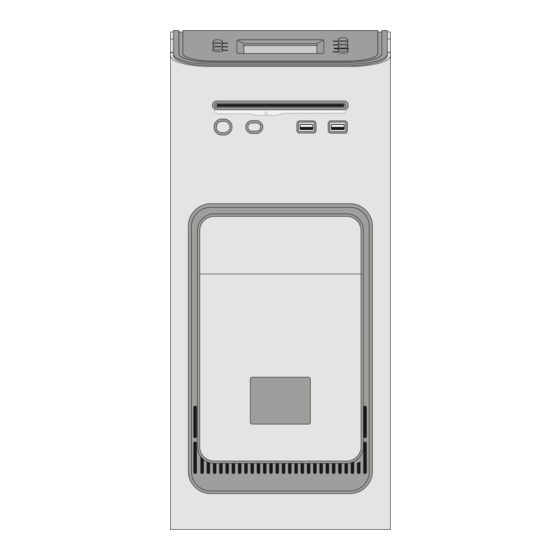
Service Guide: EFI Fiery Central integrated server Replacing parts Fiery Central integrated server overview diagrams The following figures provide an overview of FC integrated server components. Figure 2: Front panel and connector panel Front panel Connector panel Power button Power connector... -
Page 15: Figure 3: Internal Side View
Service Guide: EFI Fiery Central integrated server Replacing parts Figure 3: Internal side view Power supply USB ports (x2) and scan port Hard disk drive in bracket Motherboard CPU cooling assembly Front fan Network port DIMM slots DVI port DVD drive... -
Page 16: Figure 4: Exploded View Of Components
Service Guide: EFI Fiery Central integrated server Replacing parts Figure 4: Exploded view of components Top panel plug Front panel Hard disk drive data cables Motherboard Top panel Upper faceplate DVD drive power/data combination cable User interface board (UIB) UIB cable... -
Page 17: Figure 5: Power And Data Cable Connections
Service Guide: EFI Fiery Central integrated server Replacing parts Figure 5: Power and data cable connections Cable key From Power supply cable Power supply a. CPU power connector (PS connector) b. Motherboard power connector (J18) c. DVD drive power connector (combined with data) d. -
Page 18: Accessing Internal Components
Service Guide: EFI Fiery Central integrated server Replacing parts Cable key From Hard disk drive (HDD) data cable Hard disk drive (HDD) Motherboard connector SATA_6G_1 10 CPU fan cable CPU fan Motherboard connector CPU FAN (If present, keep the cable cover on the CPU fan cable.) Note: Power supply, DIMMs, and printer interface are not shown. - Page 19 Service Guide: EFI Fiery Central integrated server Replacing parts Avvertenza: Il server di stampa non deve essere mai sollevato afferrandolo dal pannello superiore, in quanto quest'ultimo non può sostenere il peso dell'intero sistema. Warnung: Heben Sie den Druckserver nicht an der oberen Gehäuseabdeckung an. Die obere Gehäuseabdeckung ist nicht dafür ausgelegt, das Gesamtgewicht des Systems zu tragen.
-
Page 20: Figure 6: Removing/Replacing The Side Panels
Service Guide: EFI Fiery Central integrated server Replacing parts 2 Pull the back edge of the panel away from the chassis and lift the panel off the chassis. Figure 6: Removing/replacing the side panels Right side panel Pivot post inside chassis Left side panel 3 To replace the panel, fit the front edge of the panel on the pivot post in the chassis. -
Page 21: Figure 7: Removing/Replacing The Front Panel
Service Guide: EFI Fiery Central integrated server Replacing parts Figure 7: Removing/replacing the front panel Upper faceplate 3 To replace the front panel, align the four cutouts in the panel with the power and reset buttons and front USB ports. -
Page 22: Figure 8: Removing/Replacing The Top Panel
Service Guide: EFI Fiery Central integrated server Replacing parts 4 Remove the panel from the chassis. Carefully route the UIB cable out of the hole in the top of the chassis as you remove the top panel. Figure 8: Removing/replacing the top panel... -
Page 23: Removing And Replacing Boards
Service Guide: EFI Fiery Central integrated server Replacing parts Removing and replacing boards This section includes procedures for removing and replacing the following boards: • User interface board • Motherboard The FC integrated server is shipped from the factory with a standard board configuration. If optional components have been installed, see the documentation that accompanies the particular option kit. -
Page 24: Figure 9: Diagram Of The User Interface Board (Front And Back)
Service Guide: EFI Fiery Central integrated server Replacing parts Figure 9: Diagram of the user interface board (front and back) Front view Back view Up button pad UIB cable connector to J27 Menu button pad Down button pad Jewel lights... -
Page 25: Figure 10: Removing/Replacing The User Interface Board
Service Guide: EFI Fiery Central integrated server Replacing parts 4 Remove the four screws that secure the UIB to the underside of the top panel. 5 Remove the UIB from the top panel. Be sure to remove the plastic lens that covers the display window of the UIB. -
Page 26: Motherboard
Service Guide: EFI Fiery Central integrated server Replacing parts Figure 11: Removing/replacing the UIB buttons 2 Attach the UIB cable to the connector on the back of the UIB (see Figure 10 on page 25). 3 Turn the top panel over to expose its underside and place it on a padded surface. - Page 27 Service Guide: EFI Fiery Central integrated server Replacing parts • All boards installed on the motherboard • All cables connected to the motherboard (including the motherboard power cable, CPU power cable, front panel fan cable, hard disk drive data cable, DVD drive power and data combination cable, power button cable, reset...
-
Page 28: Figure 12: Motherboard
Service Guide: EFI Fiery Central integrated server Replacing parts Figure 12: Motherboard Type A USB2.0 ports and Battery (XBT1) CPU fan power (CPU FAN) SATA_6G_0, DVD drive network ports data connection Monitor (DVI) port UIB cable (J27) Front panel fan (REAR... - Page 29 Service Guide: EFI Fiery Central integrated server Replacing parts 3 Remove the following cables from the old motherboard: Note: First remove any plastic cable clamp(s) securing internal cables and reusable tie-wraps, if present. • Front panel fan cable • Reset button cable •...
-
Page 30: Replacing The Motherboard
Service Guide: EFI Fiery Central integrated server Replacing parts Important: During service, avoid using excessive force and always place the motherboard on a grounded, non-metallic, static-free surface. Never allow any metal to touch the solder contacts on the underside of the motherboard, especially beneath the battery socket. - Page 31 Service Guide: EFI Fiery Central integrated server Replacing parts To replace the motherboard 1 If you are installing a new motherboard, do the following: • Unpack the new motherboard. • Open the load plate covering the CPU socket (see page 35) and remove the protective plastic cover on the CPU socket on the new motherboard.
- Page 32 Service Guide: EFI Fiery Central integrated server Replacing parts 2 Replace the following cables: • CPU power cable • Motherboard power cable • UIB cable • Hard disk drive (HDD) cables • DVD drive cables: • Power and data combination cable •...
-
Page 33: Replacing Parts On The Motherboard
Service Guide: EFI Fiery Central integrated server Replacing parts Replacing parts on the motherboard Before you remove and replace the DIMMs, CPU, and battery on the motherboard, shut down and open the FC integrated server (see page 18). DIMMs When installing DIMMs, note the following: •... -
Page 34: Figure 13: Cpu Cooling Assembly
Service Guide: EFI Fiery Central integrated server Replacing parts Figure 13: CPU cooling assembly CPU fan Fastener screw (1 of 4) Load plate open Heatsink Yellow triangle Important: If you remove the CPU from the motherboard in order to install it on a new motherboard, unpack the new motherboard and remove the protective plastic cover on the CPU socket. - Page 35 Service Guide: EFI Fiery Central integrated server Replacing parts 2 Remove the CPU fan cable from motherboard connector CPU FAN. 3 Remove the CPU cooling assembly. Caution: Be aware that the cooling assembly and the CPU may be very hot. You may need to let the components cool before attempting to remove them.
-
Page 36: Figure 14: Removing/Replacing The Cpu
Service Guide: EFI Fiery Central integrated server Replacing parts 4 Wipe the contact surface of the CPU (the smooth, gray side of the chip) with a clean, lint-free cloth to ensure proper contact with the new heatsink. If you remove the CPU from the motherboard to install it on a new motherboard, make sure that you completely remove any thermal compound residue on the surface of the CPU and at the base of the heatsink. -
Page 37: Battery
Service Guide: EFI Fiery Central integrated server Replacing parts 1 Prepare the CPU cooling assembly for installation. • Make sure that the motherboard is placed on a padded, static-free work surface. • Apply a fresh thermal compound square, as described in the note above. -
Page 38: Figure 15: Motherboard Battery
Service Guide: EFI Fiery Central integrated server Replacing parts VAROITUS: Paristo voi räjähtää, jos se on vaihdetaan väärän tyyppiseen paristoon. Vaihda paristo ainoastaan laitevalmistajan suosittelemaan tyyppiin. Hävitä käytetty paristo paikallisten määräysten mukaisesti. ADVARSEL: Eksplosjonsfare ved feilaktig skifte av batteri. Benytt samme batteritype eller en tilsvarende type anbefalt av apparatfabrikanten. -
Page 39: Jumpers
Service Guide: EFI Fiery Central integrated server Replacing parts 8 Reassemble the system and verify its functionality (see page 53). 9 Configure the time and date in Windows Control Panel. Important: Failure to configure the time and date will cause the FC integrated server to hang when user... -
Page 40: Power Supply
Service Guide: EFI Fiery Central integrated server Replacing parts Figure 16: Removing the fan Hook (1 of 2) Fan bracket Air flow direction Fan cable extending downward 4 Remove the fan from the chassis. To replace the fan 1 Align the fan. - Page 41 Service Guide: EFI Fiery Central integrated server Replacing parts 2 Remove the power cable from the hard disk drive. 3 Remove the power and data combination cable from the DVD drive. 4 Remove the 24-pin motherboard power cable from motherboard connector PS connector.
-
Page 42: Figure 17: Removing/Replacing The Power Supply
Service Guide: EFI Fiery Central integrated server Replacing parts Figure 17: Removing/replacing the power supply Power supply cables Power supply Chassis support beam Connector panel Screw (1 of 5) To replace the power supply 1 Support the power supply inside the chassis and align the mounting holes. -
Page 43: Hard Disk Drive
Service Guide: EFI Fiery Central integrated server Replacing parts 2 Attach the power supply to the chassis with the five screws that you removed earlier (see Figure 17 on page 42). If you are installing a new power supply, make sure to use the screws that came with it to attach the new power supply to the chassis. - Page 44 Service Guide: EFI Fiery Central integrated server Replacing parts Proper handling Important: Improper handling can damage a hard disk drive. Handle the hard disk drive with extreme care. • Use proper ESD practices when grounding yourself and the FC integrated server.
-
Page 45: Figure 18: Fc Integrated Server Hard Disk Drive
Service Guide: EFI Fiery Central integrated server Replacing parts Figure 18: FC integrated server hard disk drive Hard disk drive bracket Hard disk drive Note: Printer interface and internal cables are not shown. The hard disk drive is mounted inside a bracket. -
Page 46: Figure 19: Removing/Replacing The Hard Disk Drive Bracket
Service Guide: EFI Fiery Central integrated server Replacing parts 6 Slide the hard disk drive bracket off the shelf and lift it out of the chassis (see Figure 19). Unlock the hard disk drive bracket by moving the latch toward the connector panel, and then sliding the bracket off the bracket shelf. -
Page 47: Figure 20: Removing/Replacing The Hard Disk Drive From/In The Hard Disk Drive Bracket
Service Guide: EFI Fiery Central integrated server Replacing parts 7 Remove the four screws that attach the hard disk drive to the hard disk drive bracket (see below). Figure 20: Removing/replacing the hard disk drive from/in the hard disk drive bracket... -
Page 48: Switch Bank Assembly
Service Guide: EFI Fiery Central integrated server Replacing parts 1 If you are installing a new hard disk drive, unpack the drive. Do not drop, shake, or bump the hard disk drive. Do not touch the hard disk drive with magnetic objects or place magnetic-sensitive objects s near the hard disk drive. -
Page 49: Figure 21: Component Sled With Switch Bank Assembly
Service Guide: EFI Fiery Central integrated server Replacing parts • Front USB ports and cables Note: For more information about servicing the DVD drive, see page Figure 21: component sled with switch bank assembly Guide latch (1 of 2) Component sled Switch bank assembly with DVD drive Note: Printer interface and internal cables are not shown. -
Page 50: Figure 22: Removing/Replacing The Component Sled From The Chassis
Service Guide: EFI Fiery Central integrated server Replacing parts 4 Unharness the cables from the cable clamp(s) and tie-wraps inside the chassis. 5 Remove the component sled from the chassis (see Figure 21 on page 49). Press the guide latches on the sides of the component sled and carefully pull the sled out of its slot in the front of the chassis. -
Page 51: Figure 23: Removing/Replacing The Switch Bank Assembly
Service Guide: EFI Fiery Central integrated server Replacing parts Figure 23: Removing/replacing the switch bank assembly Component sled Screw (1 of 3) Switch bank assembly Note: Guide the cables as you remove the assembly from the component sled. Be careful not to damage the EMI gasket around the opening in the component sled. -
Page 52: Dvd Drive
Service Guide: EFI Fiery Central integrated server Replacing parts • Power button cable • Reset button cable • Speaker cable • Front panel USB port cables 5 Install the ferrite around the two front USB port cables near the motherboard. -
Page 53: Restoring And Verifying Functionality After Service
Service Guide: EFI Fiery Central integrated server Replacing parts 4 Remove the four screws that secure the DVD drive to the switch bank assembly. Set aside the screws so that you can replace them later. Note: On some systems, a small metal post in the switch bank assembly is used in place of one of the screws. - Page 54 6 Connect the power cable to the FC integrated server. 7 Connect to the network. 8 Ask the site administrator to test the Fiery Central functionalities. If the problems still exist on the FC integrated server, see the Troubleshooting sections of the user documentation.
-
Page 55: Installing Fiery Central Integrated Server Software
• Make sure the FC integrated server is shut down. 2 On the front panel of the FC integrated server, press the power button. Insert the Fiery Central System Software DVD into the DVD drive. The FC integrated server automatically boots from the DVD drive. Wait while the Windows files are loaded. -
Page 56: Installing The Hardware Security Key
Service Guide: EFI Fiery Central integrated server Installing Fiery Central integrated server Software 7 When prompted, insert the Fiery Central User Software DVD. Wait for the files to be copied to the FC integrated server. 8 Wait while the files are installed and set up on the FC integrated server. -
Page 57: Fiery Central License Manager
Fiery Central License Manager You can view the Fiery Central License by accessing the License Manager. You can also edit the Fiery Central License provided you have a new dongle and activation key. The activation key is tied to the dongle. -
Page 58: Configuring Fiery Central Integrated Server
If you have just completed installation, the Fiery Central Manager window may already be open on the screen. The Fiery Central tray icon appears on the taskbar at the lower-right corner of the screen. When you hover the cursor on the Fiery Central tray icon, Fiery Central Started appears, indicating that the Fiery Central server is running. -
Page 59: Fiery Central Configure
For information on Fiery Central setup options and Fiery Central Manager, see Fiery Central Manager Help. Fiery Central Configure After you complete installation of the Fiery Central software and restart the server, the Fiery Central tray icon appears on the taskbar at the lower-right corner of the screen. - Page 60 Or in Command WorkStation, select Device Center > General tab > General Info, and then click Configure in the lower-right corner. You can launch WebTools from the Fiery Central tray icon at any time to update your server configuration to reflect changes in your Fiery Central printing environment.
-
Page 61: Troubleshooting
Troubleshooting This chapter identifies the source of common problems that may occur with the FC integrated server and suggests ways of correcting them. Troubleshooting process Problems may occur in one of three areas: • Inside the FC integrated server • Network connections between the FC integrated server and the workstations or computers This chapter does not attempt to provide troubleshooting information for attached computers such as Windows or Mac OS computers, printer/copiers, or extensive networks. -
Page 62: Checking External Connections
Service Guide: EFI Fiery Central integrated server Troubleshooting • “Inspecting the system” on page 63 Provides a more comprehensive checklist that you can use to check the FC integrated server internally and externally. If your initial checks fail, complete this checklist before concluding that you need to replace a cable or component. -
Page 63: Checking Internal Components
Service Guide: EFI Fiery Central integrated server Troubleshooting Front panel Connector panel USB ports USB ports (x2) and scan port (RJ-45) Eject button Note: Use the reset button only if the system is unresponsive to keyboard or mouse actions. Checking internal components To check the internal components, you must remove the side and front panels of the FC integrated server. - Page 64 Service Guide: EFI Fiery Central integrated server Troubleshooting If the system you are servicing does not meet a condition listed in Table 1, and it is not obvious what action(s) you should take to fix the problem (for example, if the system hangs before reaching Idle), locate the symptom in “FC...
- Page 65 Service Guide: EFI Fiery Central integrated server Troubleshooting Table 1: Verifying the system (Continued) Conditions to verify Part and additional page references • Each DIMM is well-seated. DIMMs for FC integrated server, page 33 • DIMM edge connectors are not oxidized.
-
Page 66: Normal Startup Sequence
Service Guide: EFI Fiery Central integrated server Troubleshooting Table 1: Verifying the system (Continued) Conditions to verify Part and additional page references The hard disk drive required is: Hard disk drive, page 43 • Present • Correctly installed • Not visibly damaged •... -
Page 67: Error Messages And Conditions
EFI logo screen displays. the motherboard. Serial ATA AHCI BIOS screen Windows operating system starts up. Activity light blinks green. EFI Starting Windows screen logo screen displays. Admin login Fiery Central desktop appears after you enter the Admin password and press Enter. - Page 68 Service Guide: EFI Fiery Central integrated server Troubleshooting If replacing a component does not correct the problem, make sure that you reinstall the old component back in the FC integrated server. Table 2: FC integrated server error messages and condition...
- Page 69 Service Guide: EFI Fiery Central integrated server Troubleshooting Table 2: FC integrated server error messages and condition (Continued) Symptom Possible cause Suggested action Startup (continued) • FC integrated server is UIB cable is not connected to the 1 Recheck all cables and connections.
- Page 70 Service Guide: EFI Fiery Central integrated server Troubleshooting Table 2: FC integrated server error messages and condition (Continued) Symptom Possible cause Suggested action Startup (continued) Control panel screen Possibly one of the following: 1 Recheck all cables and connections. and Activity light •...
- Page 71 Service Guide: EFI Fiery Central integrated server Troubleshooting Table 2: FC integrated server error messages and condition (Continued) Symptom Possible cause Suggested action Startup (continued) Control panel screen Problem with the Windows 1 Recheck all cables and connections. and Activity light operating system.
- Page 72 Service Guide: EFI Fiery Central integrated server Troubleshooting Table 2: FC integrated server error messages and condition (Continued) Symptom Possible cause Suggested action System performance System performs slowly Possibly one of the following: 1 Recheck all cables and connections. and/or hangs •...
- Page 73 Service Guide: EFI Fiery Central integrated server Troubleshooting Table 2: FC integrated server error messages and condition (Continued) Symptom Possible cause Suggested action Network If you suspect a network problem, keep in mind the following: • If the FC integrated server does not appear in the list of printers on the network, another device on the network may have been assigned the same Ethernet hardware address.
- Page 74 Service Guide: EFI Fiery Central integrated server Troubleshooting Table 2: FC integrated server error messages and condition (Continued) Symptom Possible cause Suggested action Network (continued) System starts up slowly Possibly one of the following: 1 If the problem persists, ask the network administrator then displays one or to check Network Setup.
-
Page 75: Specifications
Specifications This section provides an overview of the Fiery print controller features, specifications, and safety certifications. Hardware features • Intel i5-4570S quad core 2.9GHz CPU (up to 3.6 GHz with Turbo Boost enabled) • Memory: 4GB (2 x 2GB) •... - Page 76 Service Guide: EFI Fiery Central integrated server Specifications • UL 60950-1:2007 R10.14 (TUV NRTL) • CAN/CSA C22.2 No. 60950-1:2007 +A1:2011 +A2:2014 (TUV NRTL) • GS Mark by TUV, EN60950-1:2006/A11:2009/A1:2010/A12:2011/A2:2013 EMI/EMC approvals • FCC Title 47, Part 15 Subpart B, Class A •...
-
Page 77: Servicing The Fiery Central Integrated Server With Furniture
Servicing the Fiery Central integrated server with furniture This chapter describes how to remove the FC integrated server from the furniture in order to access internal components for service. Procedures If the FC integrated server is installed in the optional furniture, you must remove it from the furniture before performing most service procedures. - Page 78 Service Guide: EFI Fiery Central integrated server Servicing the Fiery Central integrated server with furniture 1 Make sure that the FC integrated server is shut down and that all the cables are removed from the back of the FC integrated server.
- Page 79 Service Guide: EFI Fiery Central integrated server Servicing the Fiery Central integrated server with furniture 3 Remove the thumbscrews that attach the FC integrated server stability bracket to the stand. Thumbscrews Stability bracket 4 Lift the bracket and gently pull the FC integrated server away from the table top.
- Page 80 Service Guide: EFI Fiery Central integrated server Servicing the Fiery Central integrated server with furniture 5 Remove the FC integrated server left side panel (two screws) so that you can access the monitor pole tightening mechanism. Monitor pole tightening mechanism...
- Page 81 Service Guide: EFI Fiery Central integrated server Servicing the Fiery Central integrated server with furniture 6 Use the allen key to loosen the screw that secures the monitor pole to the FC integrated server. The allen key should be stored in the side drawer of the furniture.
- Page 82 Service Guide: EFI Fiery Central integrated server Servicing the Fiery Central integrated server with furniture Replacing the FC integrated server in the furniture 1 Make sure that the left side panel is removed from the FC integrated server. 2 Place the FC integrated server upright on the furniture stand. Slide the FC integrated server forward just until its front panel is aligned with the back edge of the table top.
- Page 83 Service Guide: EFI Fiery Central integrated server Servicing the Fiery Central integrated server with furniture 4 Lift up the pole assembly and insert the pole into the top of the FC integrated server so that it is inside the monitor mount.
- Page 84 Service Guide: EFI Fiery Central integrated server Servicing the Fiery Central integrated server with furniture 6 Use the handle on the stability bracket to lift the rear of the FC integrated server. Slide the FC integrated server all the way forward into the stand. Lock the FC integrated server into place with the two thumbscrews that you removed earlier.
- Page 85 Service Guide: EFI Fiery Central integrated server Servicing the Fiery Central integrated server with furniture 8 Replace the cable cover over the cables and monitor pole. Cable cover 9 Replace the allen key in the furniture drawer and continue reassembling the Fiery print controller.
-
Page 86: Index
53 clock 72 closing the system 54 EFI Fiery Central Bar CMOS 39 EFI Fiery Central Setup 58, 59 troubleshooting start up problems 68 EFI Fiery Central License Manager 57 component sled 48, 50, 52 EFI Fiery Central components... - Page 87 Service Guide: EFI Fiery Central integrated server Index motherboard battery 37 cautions about replacing 30 CPU 33, 35 description 26 front panel 39 DIMMs 33 ferrite removing 26, 29 installing on the front panel USB port cables 52 replacing 30...
- Page 88 Service Guide: EFI Fiery Central integrated server Index slot assignments, motherboard 62 software verifying functionality 53 system 30 voltages user 30 checking 12, 40 speaker motherboard connection 17 removing 49, 52 specifications 75 startup 12 normal sequence 66 static IP address, configuring 73...
Need help?
Do you have a question about the Fiery and is the answer not in the manual?
Questions and answers