Table of Contents
Advertisement
I N S T R U CT I O N M A N UA L
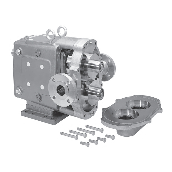
Universal 5000 Industrial Series
R OTA RY P O S I T I V E D I S P L AC E M E N T P U M P
F O R M N O . : 9 5 - 0 3 0 1 2
R E V I S I O N : 1 2 / 2 0 1 5
R E A D A N D U N D E R S TA N D T H I S M A N UA L P R I O R TO O P E R AT I N G O R S E R V I C I N G T H I S P R O D U CT.
Advertisement
Table of Contents

Related Manuals for SPXFLOW Universal 5000 Industrial Series


Summary of Contents for SPXFLOW Universal 5000 Industrial Series
- Page 1 I N S T R U CT I O N M A N UA L Universal 5000 Industrial Series R OTA RY P O S I T I V E D I S P L AC E M E N T P U M P F O R M N O .
- Page 2 Tel: (800) 252-5200 or (262) 728-1900 Fax: (800) 252-5012 or (262) 728-4904 E-mail: wcb@spxflow.com Web site: www.spxflow.com Information contained in this manual is subject to change Copyright © 2015 SPX FLOW, Inc. without notice and does not represent a commitment on the All Rights Reserved.
-
Page 3: Table Of Contents
TABLE OF CONTENTS Safety ............2 Fluid Head Assembly ....... 32 Packing Seals and Body ......32 Receiving and Warranty......3 Mechanical Seals and Body ......32-33 Installation..........4 Typical Flush Piping ..........33 Start-up Check List ........10 Rotor Clearances Back Face .......... -
Page 4: Safety
SAFETY Warnings, cautions and notes are contained in this manual. To avoid serious injury and/ or possible damage to equipment, pay attention to these messages. WARNING Hazards or unsafe practices which COULD result in severe personal injury or death and how to avoid it. CAUTION Hazards or unsafe practices which COULD result in minor personal injury or product or property damage. -
Page 5: Receiving And Warranty
SECTION I RECEIVING AND WARRANTY WAUKESHA CHERRY-BURRELL WARRANTY Seller warrants its products to be free from defects in materials and workmanship for a period of one (1) year from the date of shipment. This warranty shall not apply to products which require repair or replacement due to normal wear and tear or to products which are subjected to accident, misuse or improper maintenance. -
Page 6: Ll Installation
SECTION II INSTALLATION 95-03012... - Page 7 INSTALLATION PUMP INSTALLATION The installation of your Waukesha pump and its piping system should follow the practices described to give optimum performance, and be in accordance with local codes and restrictions. All system equipment, such as motors, sheaves, drive couplings, speed reducers, etc., must be properly sized to insure satisfactory operation of your Waukesha pump within its limits.
- Page 8 GUARD Adjustable leg base, commonly used for sanitary pumps. For washdown under base. Can be easily moved or repositioned. GUARD Portable bases-for movement to different locations. WARNING TO AVOID SERIOUS INJURY, DO NOT INSTALL OR SERVICE PUMP UNLESS ALL POWER IS OFF AND LOCKED OUT. 2.
- Page 9 Piping Layout Inlet side: Slope piping up to inlet to avoid air pocket. AIR POCKET INLET INLET OUTLET OUTLET CORRECT WRONG INLET OUTLET Inlet side-use check valves to keep inlet line full, particularly with low viscosity fluids, and in start- stop operation.
- Page 10 A particular relief valve design will have a charac- teristic curve such as shown. The ''cracking pres- BY-PASS sure" can usually be set by spring adjustment, or PRESSURE by adjustable pneumatic pressure, etc. Flow will begin to bypass when this ''cracking pressure'' is reached.
- Page 11 In-line Drives. For initial pump installation, and for rechecking alignment, the following steps are advised: Use a flexible coupling to connect the drive to the pump. Many different types are available, including couplings with slip or overload provision. RUBBER SLIP FLUID GEAR FLEXIBLE...
-
Page 12: Lll Start-Up Check List
Aligning belt and chain drives. Using straight-edges and visual check: MOVE DRIVE TO CORRECT ANGULAR AND PARALLEL MISALIGNMENT. KEEP DISTANCE TO MINIMUM After piping is complete and before belts are installed, turn pump shaft manually to see that it turns freely. -
Page 13: Troubleshooting A Pump System
SECTION IV TROUBLESHOOTING A PUMPING SYSTEM Once a pump is properly selected and installed in a system, operation should be trouble free. However, in existing systems, or as pump and system conditions change, problems may develop. Following are some troubleshooting hints to help identify and solve problems. WARNING WARNING TO AVOID POSSIBLE SERIOUS INJURY,... - Page 14 TROUBLESHOOTING Problem Probable Causes Solutions No flow, pump "Air" lock. Fluids which "gas off", Manual or automatic air bleed from not priming or vaporize, or allow gas to come pump or lines near pump out of solution during off periods Extra clearance rotors, worn pump Increase pump speed, use foot valve to improve priming...
- Page 15 TROUBLESHOOTING Problem Probable Causes Solutions Fluid vaporization NIPA too Low Select larger pump size with (''starved'' pump inlet) smaller NIPR Fluid viscosity greater Reduce pump speed and accept than expected lower flow, or change system to reduce line losses. Fluid temperature higher than Reduce temperature, reduce speed expected (vapor pressure higher) and accept lower flow or change...
- Page 16 TROUBLESHOOTING Problem Probable Causes Solutions Noisy operation • Rotor to body contact Distortion of pump due to Reassemble pump or re-install improper piping installation. piping to assure free running Pressure higher than rated Reduce pressure if possible Worn bearing Rebuild with new bearings. Lubricate regularly Worn gears Rebuild with new gears.
-
Page 17: Operation
SECTION V OPERATION Normal operation covers a speed range of 0-600 RPM and pressure range of 0-200 PSI. Temperature range with standard rotors is -40° to 200° F. and with hot clearance rotors, 180° to 300° F. (For operation at higher temperatures, consult SPX FLOW.) See START-UP CHECK LIST (Page 10) and TROUBLESHOOTING (Page 11-14) for additional operation information. -
Page 18: Vl Maintenance
SECTION Vl MAINTENANCE GENERAL In the maintenance of pumps it is important to recognize when parts are wearing excessively. Detecting wear in the early stages will let you repair your pump at minimum cost and get it back into operation at the earliest date. Periodic cleaning and a simple “look-feel”... -
Page 19: "Feel" Checks
3. CHECK SHAFT SHOULDER for deterioration. (Rotor hub locates against.) Cause Corrective Measure SHOULDER Reshim or replace Loose rotor shaft... to maintain correct running clearances. (See table 1, Page Remove gear and Loose gears....inspect key, keyway and shaft. If all are in good condition, re- assemble and retighten gear retaining nuts to... -
Page 20: Seal Maintenance
SEAL MAINTENANCE PACKING GLAND 1. Packing Seal a. To suit the required service, a variety of packing materials and replaceable shaft sleeves are available. Standard packing material is braided teflon-compounds. Standard sleeves are 316 stainless; optional sleeves of ceramic coated stainless are SLEEVE available. -
Page 21: Mechanical Seals
e. Refer to parts list and drawing for your pump. As- semble packing components into body cavity as shown in the drawing. Stagger the end joints in the packing rings so they do not line up. Snug up gland but DO NOT tighten. Make final adjustment of packing glands after startup. -
Page 22: Annual Maintenance
Dual Inside and Outside Seal SEAT RETAINER (GLAND) a. Turn on seal water. b. If water leaks past the outside seal, flush off any scale or crusted product that may have accumulated around the shaft and seal area and seal springs. c. -
Page 23: Vli Factory Reconditioning
SECTION Vll FACTORY RECONDITIONING Waukesha Industrial pumps are designed so that they may be factory reconditioned twice and backed with a new pump warranty each time. Factory reconditioning involves replacement of all worn parts such as shafts, bearings, oil seals, gears, etc. -
Page 24: Rotor Removal
2. Remove O-ring from cover groove and inspect. Discard if not in good condition. REMOVE ROTORS 3. Turn shaft to orient rotors as shown for easy removal one at a time. a. To remove rotor retainer bolts, straighten lock clip tabs using a screw driver or drift. Then, when clear, use a conventional wrench and a sharp counterclockwise impact to loosen bolt. -
Page 25: Shaft, Bearings And Gear Removal
REMOVE SHAFTS, BEARINGS AND GEAR CASE GEARS - ALL MODELS GEAR CASE COVER CAP SCREW OIL SEAL OIL DRAIN PLUG SILICONE SEALANT 1. Remove oil drain plug and drain oil. 2. Remove cap screws from gear case cover. 3. Pull cover off shaft extension. If cover sticks, use soft hammer to loosen it. 4. - Page 26 SHAFT REMOVAL WOOD BLOCK 7. Prevent shafts from turning by wedging a wooden block between the gears. 8. Use spanner wrench or drift to remove gear lock GEAR nuts. Gears will be removed later.See step 10 LOCK NUTS below. RETAINER TAPE NOTE: Protect liquid end of shafts by wrapping them with tape.
- Page 27 11. Scrape silicone sealant; press out and discard BEARING RE- grease seal from front bearing retainers. GREASE TAINER SEAL SILICONE SEALANT SHIM REAR GREASE 12. Remove shims. If they are to be re-used, SEAL identify them with the shaft on which they were used.
-
Page 28: Assembly Procedures
SECTION IX ASSEMBLY PROCEDURES MODEL 5040 Shaft Assembly 1. Front Bearing Assembly GREASE a. Coat front bearing area of shaft with grease. Place upright in hydraulic press with spline end down. b. Unwrap front bearing assembly. PRESS AGAINST INNER RACE ONLY SHIELD FRONT c. -
Page 29: Front Bearing, 5050, 5060, 5070, 5080
MODEL 5050, 5060, 5070 AND 5080 Shaft Assembly MODEL 5080 SHOWN GREASE 1. Front Bearing Assembly a. Coat front bearing area of shaft with grease. Place upright in hydraulic press with spline end down. SPACER CONE AND ROLLER b. Unwrap front bearing assembly. Do not inter- change parts of one bearing assembly with an- other. -
Page 30: Rear Bearing, All Models
MODEL 5080 only i. Clamp shaft behind lock nut in a soft jawed vise and drive lock nut tight using a spanner wrench or drift. (See Table 2 on Page 35 for torque requirements). j. Bend lock washer tab into groove on nut to secure assembly. -
Page 31: Gear Case Assembly
ROLLER d. Apply grease again. Slip bearing cup over roller assembly. Install both inner and outer spacers. Place remaining cup onto outer spacer and press on SPACERS the remaining cone and roller assembly. (See Table 4 on Page 35.) Be sure outer spacer is concentric on shaft. ROLLER Gear Case Assembly 1. -
Page 32: Bearing Retainer Adjustment
e. Secure shaft assemblies in gear case with .010-.050" SHIM HERE IF REQUIRED bearing retainers. No silicone sealant at this time. NOTE: Retainer must seat firmly against bearing and leave .010"-.050" clearance with gear case. BEARING RETAINER Use shims between bearing and retainer if re- quired. -
Page 33: Timing Gear And Cover Assembly
TIMING GEAR AND GEAR COVER ASSEMBLY- ALL MODELS 1. Place keys into shaft key slots. Slide gear with single punch mark onto drive shaft. Slide gear with two punch marks onto the short shaft with punch marks straddling single mark of drive gear. -
Page 34: Fluid Head Assembly
SLEEVE FLUID HEAD ASSEMBLY Mechanical Packing 1. Place O-rings into grooves on shafts then slip sleeves onto shafts with pin indexed into notch on shaft. O-RING 2. For parts identification and correct order of assembly see packing parts list and sectional draw- ing in Section XII, starting on page 38. -
Page 35: Typical Flush Piping
SEAT RETAINER 3. Double Seal with Flushing RETAINER GASKET OUTER SEAL a. Place outer seal rotating member onto shaft INNER SEAL with seal face toward fluid head. Lock seal onto shaft at proper location. (See seal assembly drawing for correct location dimension.) SEE ACTUAL b. -
Page 36: Back Face
PROPER CLEARANCES 1. All Waukesha pumps are designed with close A= BACK FACE CLEARANCE running clearances and the back face clearance is B=ROTOR TO BODY CLEARANCE established with shims during assembly. The shaft C=FRONT FACE CLEARANCE is positioned with shims behind the front bearing and locked into bearing gear case. -
Page 37: Reference Tables
SECTION X REFERENCE TABLES AND REPAIR PARTS LIST TABLE 1. STANDARD ROTOR CLEARANCES* BACK ROTOR FRONT MODEL FACE TO BODY FACE 5040 .002-.0025 .003-.004 .0025-.005 5050 .002-.0025 .003-.004 .004-.006 5060 .0025-.003 .0035-.005 .004-.006 5070 .004-.005 .004-.0055 .004-.008 5080 .005-.006 .005-.007 .005-.009 *For non-standard rotor clearance, contact Application Engineering at Waukesha Cherry-Burrell... -
Page 38: Waukesha Internal By-Pass Relief Valve
SECTION XI WAUKESHA INTERNAL BY-PASS RELIEF VALVE FOR INDUSTRIAL STAINLESS STEEL("I")AND DUCTILE IRON ("Dl") PUMP MODELS 5040, 5050, 5060, 5070, and 5080 Adjustable spring tension operated piston opposite 2. Turn on pump. the pumped fluid. The pump cover is reversible for right or left hand flow direction. - Page 39 Relief Valve Data 5050/5060 Pump Model 5040 2.776 Valve face area (sq. inches) 2.483 Maximum valve travel 0.96 inches) 0.9 1 Spring rate (lbs per 0.1 inch) Ref. spring part nurnber 000-076-006 Adjustment screw pitch ( threads per inch ) Amount of spring compression Product cracking pressure/ (No.
-
Page 40: Universal Industrial Parts Lists
SECTION XII UNIVERSAL INDUSTRIAL PARTS LIST 5040 95-03012... - Page 41 5040 95-03012...
-
Page 42: 5050 Pump
5050 95-03012... - Page 43 5050 95-03012...
-
Page 44: 5060 Pump
5060 95-03012... - Page 45 5060 95-03012...
-
Page 46: 5070 Pump
5070 95-03012... - Page 47 5070 95-03012...
-
Page 48: 5080 Pump
5080 95-03012... - Page 49 5080 95-03012...
-
Page 50: 5040 Standard Seals
5040 PACKING AND SEALS MECHANICAL PACKING (STANDARD SEAL PACKAGE) Item Part No. Description STD 299 022 NUT 6100x2 87-699 TUBE-1 .187"x.030"W COPPER 0B1 004 000 GLAND SS 0B1 033 000 PACKING 0B1 033 100 PACKING SPACER 0B1 043 300 GASKET INSERT 0B1 047 000 LANTERN RING-GLASS FILLED 36-41 HEX NUT, 5/16-18 18-8 REG... -
Page 51: 5050 Standard Seals
5050 PACKING AND SEALS MECHANICAL PACKING (STANDARD SEAL PACKAGE) 87-699 TUBE-1 .187"x.030" COPPER IN. 43-22 LOCK WASHER, 1/4" 18-8 REG. 0C1 033 100 PACKING SPACER 30-62 HHCS 1/4-20 x .50" 18-8 0C1 047 000 RING, LANTERN GLASS FILLED 0C1 050 000 STUD, 3/8-16 .375D 1.87LG 36-45 HEX NUT, 3/8-16 18-8 REGULAR 0C1 051 000 PACKING, RET RING 316SS... -
Page 52: 5060 Standard Seals
5060 PACKING AND SEALS MECHANICAL PACKING (STANDARD SEAL PACKAGE) 87-699 TUBE-1 .187"x.030" COPPER IN. 43-22 LOCK WASHER, 1/4" 18-8 REG. 0C1 033 100 PACKING SPACER 30-62 HHCS, 1/4-20 x .50" 18-8 0E1 047 000 RING, LANTERN GLASS FILLED 0C1 050 000 STUD, 3/8-16 .375D 1.87LG 36-45 HEX NUT, 3/8-16 18-8 REGULAR 0C1 051 000 PACKING, RETAINING RING 316SS... -
Page 53: 5070 Standard Seals
5070 PACKING AND SEALS MECHANICAL PACKING (STANDARD SEAL PACKAGE) Item Part No. Description 36-41 HEX NUT, 5/16-18 18-8 REG 000 299 032 FITTING, MALE BRASS 200 004 000 PACKING GLAND 200 032 000 PACKING SPACER 200 033 000 PACKING C-13 200 047 000 LANTERN RING, GLASS FILLED 200 050 000... -
Page 54: 5080 Standard Seals
5080 PACKING AND SEALS MECHANICAL PACKING (STANDARD SEAL PACKAGE) Item Part No. Description 0C1 050 000 STUD, 3/8-16 .375D 1.87LG 36-45 HEX NUT, 3/8-16 18-8 REG. 000 299 032 FITTING, MALE BRASS 200 317 000 TUBE, FLUSHING 5/16 STEEL 4" 300 004 000 PACKING GLAND 20-138... -
Page 55: Stuffing Box Dimensions
95-03012... -
Page 56: Warning Label Replacement
LABEL PLACEMENT 33-62 33-60 33-61 BOTTOM 33-63 Relative Sizes PUMP MODEL 33-62 33-60 33-63 • • **5040 • • 5050 LEFT SIDE • • 5060 • • 5070, 5080 **Place label behind grease fittings • (on right side) = 2 each RIGHT SIDE Part Number 001 061 APPLICATION INSTRUCTIONS... - Page 58 Delavan, WI 53115 P: (262) 728-1900 or (800) 252-5200 F: (262) 728-4904 or (800) 252-5012 E: wcb@spxflow.com SPX FLOW, Inc. reserves the right to incorporate our latest design and mate- rial changes without notice or obligation. Design features, materials of construction and dimensional data, as described in this bulletin, are provided for your information only and should not be relied upon unless confirmed in writing.
Need help?
Do you have a question about the Universal 5000 Industrial Series and is the answer not in the manual?
Questions and answers