CTI 2500 Series Quick Start Installation Manual
Compact controller
Hide thumbs
Also See for 2500 Series:
- Quick start manual (73 pages) ,
- Manual (4 pages) ,
- Quick start manual (4 pages)
Table of Contents
Advertisement
Quick Links
®
CTI 2500 SERIES
COMPACT CONTROLLER
QUICK START INSTALLATION GUIDE
Purpose of this Document
This document is designed to assist you in unpacking and installing the CTI 2500
®
Series
Compact controller. For additional information, see the CTI 2500 Series
Controller Installation and Operation Guide and the CTI 2500 Series Programming
Reference Manual, available on our CTI web site (see link below).
www.controltechnology.com/support/manuals/.
Product Overview
The CTI 2500 Series Compact controller provides all the capabilities of the CTI
2500 Series Classic Controller in a smaller form factor, combining the functionality
of a programmable logic controller and a loop controller in one product and
providing operational compatibility with CTI 2500 Series and Siemens SIMATIC
®
505
products. A particular model number of the 2500 Series Compact controller
provides the same features as the 2500 Series Classic controller with the identical
model number. User programs developed for the 2500 Series Classic controllers
will execute without modification on the 2500 Series Compact controllers.
Unpacking the Module
Since the components on the CTI 2500 Series Compact controller can be damaged
by static electricity discharge, the product is shipped in a special anti-static bag.
Static control precautions should be followed when removing the product from the
bag and when handling the product during configuration
After opening the shipping carton, remove anti-static bag containing the controller. Do not discard the static
bag. Always use this bag for protection against static damage when the module is not inserted into the I/O
base.
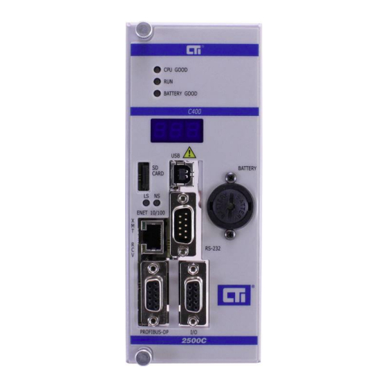
Setting the CTI 2500 Series Compact Controller Switches
Switches on the CTI 2500 are used to select operational parameters such as battery
power, serial port baud rate and electrical interface, TCP/IP program port, remote I/O
media and polling characteristics, and firmware update mode.
The switches are located on the display circuit board, which is behind the front panel
near the top as indicated by the arrow in the accompanying illustration. .
Figure 2 shows the individual switch settings. See the CTI 2500 Series Controller
Installation and Operation Guide for additional information.
Page 1
CTI 2500 Series Compact Controller Quick Start Guide (P/N 062-00465-011)
Advertisement
Table of Contents

Subscribe to Our Youtube Channel
Related Manuals for CTI 2500 Series


Summary of Contents for CTI 2500 Series
- Page 1 CTI 2500 SERIES COMPACT CONTROLLER QUICK START INSTALLATION GUIDE Purpose of this Document This document is designed to assist you in unpacking and installing the CTI 2500 ® Series Compact controller. For additional information, see the CTI 2500 Series Controller Installation and Operation Guide and the CTI 2500 Series Programming Reference Manual, available on our CTI web site (see link below).
- Page 2 SW7: Redundant Base Polling Switch 7 allows you to reduce the I/O scan time of the CTI 2500 controller in I/O configurations that use only one Remote Base Controller (RBC) per base. When the switch is set to the O...
- Page 3 After a subsequent power up with the switch in the O position, the controller will automatically generate an IP address as described later in this document. Also see the 2500 Series Controller Installation and Operation Guide for additional information.
- Page 4 When connected to the serial or USB port, you can set the IP address and other IP parameters using PLC Workshop (V4.11 or greater) or IPSET, a standalone utility that you can download from the CTI web site. Using the Ethernet Port Firmware version 8.02 and above allows you to set the IP address and other IP parameters when connected...
- Page 5 CTI APTNet on the PC. Workshop allows you to program the CTI 2500 using USB, Ethernet, or RS-232 ports. In order to use the USB port, you must install a CTI USB device driver on your PC. This driver may be downloaded from www.controltechnology.com/downloads.
- Page 6 Status Word 260 and Status Word 261 using your programming software or by using your web browser to access the web server embedded in the CTI 2500 controller. You may determine the current firmware level by accessing the CTI web site - http://www.controltechnology.com/support/software-revision/...
Need help?
Do you have a question about the 2500 Series and is the answer not in the manual?
Questions and answers