CTI 2500-C100 Nstallation And Operation Manual

CTI 2500-C100 Nstallation And Operation Manual

2500 series
Table of Contents

Advertisement

®
CTI 2500 Series
Controller
INSTALLATION AND OPERATION GUIDE
Version 2.8
CTI Part # 062-00370
2500IOG

Advertisement

Table of Contents
loading
Need help?

Need help?

Do you have a question about the 2500-C100 and is the answer not in the manual?

Questions and answers

Subscribe to Our Youtube Channel

Summary of Contents for CTI 2500-C100

  • Page 1 ® CTI 2500 Series Controller INSTALLATION AND OPERATION GUIDE Version 2.8 CTI Part # 062-00370 2500IOG...
  • Page 2 Every effort has been made to ensure the accuracy of this document; however, errors do occasionally occur. CTI provides this document on an “as is” basis and assumes no responsibility for direct or consequential damages resulting from the use of this document.
  • Page 3 8.02. (Ethernet port IP address change, embedded web server IP configuration page, reset to factory default, display subnet in CIDR format). Added sections to Installation chapter regarding setting IP address and automatic IP address assignment. CTI 2500 Installation and Operation Guide V2.8...
  • Page 4 Added a note to Appendix B stating that status words 243 and above are not supported by Siemens 505 controllers. Revised note in Firmware Update section that appeared to limit supported SD cards to 4GB and below CTI 2500 Installation and Operation Guide V2.8...
  • Page 5 This Installation and Operation Guide provides reference information for CTI 2500 Series Classic controllers and CTI 2500 Series Compact controllers. The information in this manual is directed to individuals who will be installing and operating the controller as well as those who will be designing systems that use the controller.
  • Page 6 Notes alert the user to special features or procedures. CAUTION Cautions alert the user to procedures that could damage equipment. WARNING Warnings alert the user to procedures that could damage equipment and endanger the user. CTI 2500 Installation and Operation Guide V2.8...
  • Page 7: Table Of Contents

    Special Function Programs and Subroutines ............. 32 Analog Loops ....................... 33 Analog Alarms ......................33 CHAPTER 4 I/O SUPPORT ....................35 I/O Concepts ........................ 35 I/O Support ........................36 Dual RBC Support ....................... 39 Profibus DP I/O ......................41 CTI 2500 Installation and Operation Guide V2.8...
  • Page 8 Fatal Error Codes ........................86 Task Code Errors........................88 APPENDIX B. – SYSTEM STATUS WORDS ..............91 APPENDIX C. – IP ADDRESS INFORMATION ..............99 IP Address Nomenclature ...................... 99 Selecting IP Addresses ......................100 CTI 2500 Installation and Operation Guide V2.8...
  • Page 9 I/O Port Pinout ........................108 Profibus Port Pinout ......................108 APPENDIX G. – SD CARD REQUIREMENTS ..............109 CTI 2500 Series Classic Controller SD Card Requirements ..........109 CTI 2500 Series Compact Controller SD Card Requirements ........... 109 Data Storage Capacity ......................109 Physical Size .........................
  • Page 11: Chapter 1 Overview

    Classic: 2500 Series Classic controllers (2500-Cxxx) are physically compatible with the Siemens SIMATIC 505 product line and may be installed in a CTI 2500 Series base or a Siemens SIMATIC 505 base, along with CTI 2500 Series Classic I/O and SIMATIC 505 I/O.
  • Page 12: I/O Support

    1.5 Ethernet TCP/IP Connectivity The CTI 2500 controller provides a local 10/100 Mb Ethernet port, allowing it to be connected to plant floor networks. Programming software that supports the TCP/IP protocol, such as FasTrak ®...
  • Page 13: Serial And Usb Connectivity

    1.7 Serial and USB Connectivity The CTI 2500 controller provides a traditional 9 pin serial port and a USB (Universal Serial Bus) port which may be used to program the controller and control its operation. See CHAPTER 7 for more information.
  • Page 14: 
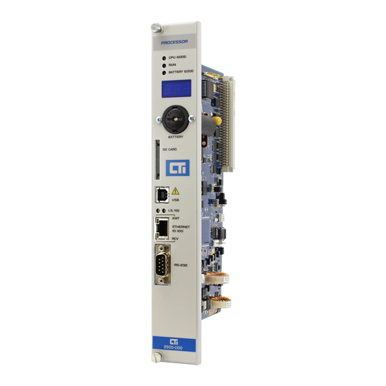
2500 Series Classic Controller Front Panel

    LS – Link Status NS- Network Status 7. Ethernet Port XMT LED – Flashes when transmitting RCV LED – Flashes when receiving 8. Serial Communications Port RS-232/RS-422) 9. Profibus DP Port 10. Remote I/O Port CTI 2500 Installation and Operation Guide V2.8...
  • Page 15: 2500 Series Compact Controller Front Panel

    NS- Network Status 6. Battery Holder 7. Ethernet Port XMT LED – Flashes when transmitting RCV LED – Flashes when receiving 8. Serial Communications Port RS-232/RS-422) 9. Profibus DP Port 10. Remote I/O Port CTI 2500 Installation and Operation Guide V2.8...
  • Page 16: Operational Status Leds

    See APPENDIX G. – SD CARD REQUIREMENTS. 1.14 USB Port The CTI 2500 controller provides a type B USB (Universal Serial Bus) connector. The port can be used to program the controller. A special PC driver that emulates a standard COM port is required.
  • Page 17: Ethernet Port

    (output only) by repositioning a jumper on the printed circuit board (see Section 2.4). You can then use the PRINT statement to send a character string to the printer our output device. See the CTI 2500 Series Programming Reference Manual for additional information.
  • Page 18: Product Models

    1.20 Product Models The CTI 2500 Classic controller (2500-Cxxx) is available in four models. The CTI 2500 Compact (2500C-Cxxx) controller is available in three models. The following table lists the model characteristics. Feature 2500-C100 2500-C200 2500-C300 2500-C400 2500C-C100 2500C-C200 2500C-C300...
  • Page 19: Chapter 2 Installation

    If you or your company are using CTI controllers with equipment that requires the presence of a person (such as an operator or attendant), you should be aware of this potential safety hazard and take appropriate precautions.
  • Page 20 In addition to connecting the controller rack and power supply to earth ground, you must ensure that the power supply, controller and all modules installed in the base are installed securely and that the thumbscrews are tightened. CTI 2500 Installation and Operation Guide V2.8...
  • Page 21: Unpacking The Controller

    USB port using PLC Workshop (version 4.11 and above) or by IPSET, a utility program provided by CTI. Firmware version 8.02 and above allows you to set the IP address via the Ethernet port using PLC workshop or the controller embedded web server. See Section 7.4 for additional information.
  • Page 22: Setting The User Switches

    LOSED ) position. NOTE: 2500 Series controllers are shipped with the battery switch in the Open (disconnected) position. To enable battery backup, you must place the battery switch in the Closed (connected) position. CTI 2500 Installation and Operation Guide V2.8...
  • Page 23 (such as the serial port or a Special Function module) from modifying the User Program. Other users connected to Port 1505 or 4450 on the local Ethernet port cannot modify the user program because attempts to modify the user program will be rejected. CTI 2500 Installation and Operation Guide V2.8...
  • Page 24 SW8: Unconfigured Base Polling (firmware version 7.07 and above) Switch 8 allows you to reduce the I/O scan of the CTI 2500 controller by not polling bases that are enabled but unconfigured. This capability is especially important for APT users needing to reduce scan time, since APT programming software does not provide a means to manually disable a base.
  • Page 25 ) position, the controller will start up in the normal operating mode. When the switch is ) position, the controller will start up in the firmware update mode. See CHAPTER LOSED 10 for information about updating the controller firmware. CTI 2500 Installation and Operation Guide V2.8...
  • Page 26: Setting The User Jumpers Or Auxiliary Switches

    Closed Open 2500 Series Compact Controllers CTI 2500 Series Compact Controller use a set of Auxiliary Switches, located next to the User switches, instead of jumpers. The switches are numbered 1 – 6. The O position is equivalent to the C jumper position.
  • Page 27 Auxiliary switches be in the Off position F or 6 Reserved Note 1: Model C400 controllers with firmware version 8.01 and above will also report additional control relays (C32769 – C56320) when Jumper A is closed. CTI 2500 Installation and Operation Guide V2.8...
  • Page 28: Physical Installation

    ON, this LED will illuminate. If the LED is off, the battery is missing or bad or the battery switch is off. This LED must be ON in order to retain the User Program and related data when power is removed. CTI 2500 Installation and Operation Guide V2.8...
  • Page 29: Setting The Controller Ip Parameters

    2500 controller embedded web server with your PC web browser. 2.8 Automatic IP Address Assignment The 2500 controller is shipped from CTI with the IP parameters cleared. After you power up the controller, the IP address will be displayed as 0.0.0.0. When you connect the Ethernet port to a switch or PC, the controller will automatically generate a temporary IP address.
  • Page 31: Chapter 3 User Programming

    CHAPTER 3 USER PROGRAMMING 3.1 Overview The CTI 2500 controller provides several methods for programming a control application. • Relay Ladder Programming • Special Function Programming • Analog Loops • Analog Alarms An overview of these capabilities is provided below. Comprehensive information can be found in the CTI 2500 Programming Reference Manual.
  • Page 32: Special Function Programs And Subroutines

    LEAD/LAG function that can be used with cyclic applications. Program Flow These instructions alter the order in which instructions are executed. They include the ability to call subroutines, to branch to a label, and to implement conditional branching (If, Then, Else). CTI 2500 Installation and Operation Guide V2.8...
  • Page 33: Analog Loops

    Loops are typically executed on a cyclic basis, independent of the user RLL or SF program logic. Some models of the CTI 2500 also support the capability of calling a PID loop from the RLL. Loops may be cascaded, where the output of one loop becomes the input for the next loop. A loop may call a Special Function program to perform additional calculations.
  • Page 35: Chapter 4 I/O Support

    (I/O) data and updates the physical I/O modules. 4.1.1 I/O register The CTI 2500 controller contains two I/O registers, which are memory areas used to hold I/O values. The discrete I/O register contains Boolean values (0 or 1). The word I/O register contains 16 bit word values.
  • Page 36: I/O Support

    Ethernet communications modules, and specialty modules, such as vibration recording modules and warm backup modules. In addition, CTI provides remote base racks and remote base controllers. For a complete list of CTI products, log on to the CTI Web site (www.controltechnology.com).
  • Page 37 For each cable type, there is a maximum cable length. As the figure below indicates, the maximum cable length is measured from the CPU to the most distant tap. Note that a terminating resistor must be installed on the end terminal blocks. CTI 2500 Installation and Operation Guide V2.8...
  • Page 38 When multiple connections are required in close proximity, you should connect the equipment to a single terminal block instead of dedicating a terminal block to each connection. See the figure below for connection options. CTI 2500 Installation and Operation Guide V2.8...
  • Page 39: Dual Rbc Support

    RS-485 network. Coaxial dual media cabling is not supported. A dual RBC configuration consists of two remote base controllers installed in a special base (CTI 2500-R11-A or Siemens 505-6511). These bases also support the installation of dual power supplies, providing redundant sources of power The dual RBC configuration provides redundant control of the I/O base.
  • Page 40 RBC connections. NOTE: You can use either a CTI 2500-RIO-A (firmware version 7.03 or higher) or a Siemens 505-6851-B remote base controllers in a dual RBC configuration; however, you cannot intermix CTI and Siemens RBCs in the same base.
  • Page 41: Profibus Dp I/O

    Network data rates may be limited by the network configuration. 4.4.1 Connecting the Profibus Network Cable Selection The Profibus network attaches to the Profibus DP connector on the front panel of the CTI 2500 controller using shielded twisted pair cable. The following table specifies the characteristics of the cable.
  • Page 43 Up to 32 devices can be connected on a single segment. To increase distance or the number of devices supported, segments can be interconnected by using repeaters. Up to 10 segments may be connected together. R = Repeater Slave Slave Slave Slave Slave Slave Segment Segment CTI 2500 Installation and Operation Guide V2.8...
  • Page 44 3. Merge the resulting .2bf file from the Profibus configuration into your programming software. 4. Using the programming software, assign the slave I/O points to I/O register addresses. For additional information regarding Profibus configuration, see the help documentation for PLC Workshop and Com Profibus. CTI 2500 Installation and Operation Guide V2.8...
  • Page 45 In this case, you should set the scan mode to Synchronous or employ programming techniques to ensure that all outputs remain on for more than one scan. CTI 2500 Installation and Operation Guide V2.8...
  • Page 46 2500 controller user logic and saved in V memory table by using the RLL Read Slave Diagnostic (RSD) instruction. The saved information can then be processed in user logic or read by HMI workstations. See the CTI 2500 Programming Reference Manual for details regarding the RSD instruction.
  • Page 47: Chapter 5 Controller Memory

    CHAPTER 5 CONTROLLER MEMORY 5.1 Overview The CTI 2500 controller contains several different types of memory, each with a specific purpose. The memory types are described in the following sections. 5.2 User Program RAM The User Program and related data is stored in battery-backed memory. As long as battery power is present, the contents of battery-backed memory will be maintained over a power cycle.
  • Page 48 The scan configuration includes the scan type, the scan time, the task codes per scan, the scan watchdog value, and the analog scan time slice configuration. See CHAPTER 6 for a description of the CTI 2500 scan. CTI 2500 Installation and Operation Guide V2.8...
  • Page 49: Flash Memory

    Password Data The password data includes the user password, the access level, and the enable status. For additional details, refer to the CTI 2500 Programming Reference Manual. 5.3 Flash Memory Non-volatile flash memory is used to store the operating firmware for the controller. The operating firmware can be updated in the field.
  • Page 51: Chapter 6 Scan Timeline

    The controller executes most tasks in a cyclical sequential order. This order is referred to as the controller scan. There are two major divisions to the CTI 2500 controller scan; the discrete scan and the analog scan. The discrete scan contains elements commonly found in traditional programmable logic controllers.
  • Page 52 Each task in the analog scan is allotted a time slice in which to run. Except for the diagnostic task, whose time slice is fixed, you can configure the time allocated to each task, allowing you to optimize the controller performance. See the CTI 2500 Programming Reference Manual for time slice configuration specifications.
  • Page 53: Plc Scan Types

    6.1.3 Cyclic RLL The Cyclic RLL is executed on a user-specified interval. When queued for execution, it will interrupt any other task in the discrete scan or the analog scan. See the CTI 2500 Programming Reference Manual for additional information.
  • Page 54: Scan Modes

    PROGRAM mode places both scans in program mode. For special application needs, it is possible to set the operating mode of the discrete scan and analog scan separately. The following sections describe the operating modes of each scan. CTI 2500 Installation and Operation Guide V2.8...
  • Page 55 6.3.1 Discrete Scan Mode The CTI 2500 supports the following discrete scan modes. Mode Description PROGRAM When the Discrete Scan is in PROGRAM mode, the RLL tasks do not execute. However, the NORMAL I/O and Special Function I/O tasks continue to operate normally.
  • Page 57: Chapter 7 Communications

    TISOFT and APT, which are DOS applications, cannot access the USB programming port. 7.3.1 Installing the CTI USB Driver Before you can use the USB port for programming, you must install the CTI-supplied driver on the PC. This driver provides an interface to the application program that emulates a standard COM port.
  • Page 58: Ethernet Communications

    7.3.2 Using the USB Driver The USB driver is initiated when the CTI 2500 controller is connected to the USB port on your PC. When installed, the driver will default to the lowest-numbered serial port that has not been assigned (usually COM3).
  • Page 59 IP parameters can disrupt the control process. However, you can enable this feature by setting SW11 to the closed position. See section 2.3. Because of the potential risk, CTI recommends that you set SW11 back to the Open position before placing the controller in a production environment.
  • Page 60 PLC WorkShop. To use the programming port, connect to TCP port 4452. This port supports all programming, data access, and control requests. Only one client may be connected to the programming port at a time. The CTI 2500 gives priority to all requests to the port 4452. UDP is not supported.
  • Page 61 To use the Data Access port, you should connect to TCP port 4450. To provide compatibility with installations using the CTI 2572 and 2572-A, you may also connect to the Data Access port using TCP port 1505. A total of three concurrent TCP connections to either port 4450 or port 1505 are allowed.
  • Page 63: Chapter 8 System Restart Options

    • The complete restart clears all analog outputs • The complete restart clears all retentive relays • The complete restart restores the timer/counter/drum presets from ladder See the following section for more information. CTI 2500 Installation and Operation Guide V2.8...
  • Page 64: System Restart Table

    . Assumes flash contains a valid program. If not valid, the source is set to RAM (see RAM column). . If controller was in Fatal Error, the controller will start in Program Mode. CTI 2500 Installation and Operation Guide V2.8...
  • Page 65: Chapter 9 Troubleshooting

    CHAPTER 9 TROUBLESHOOTING This section provides information that you may find useful in diagnosing and correcting problems you may encounter with using the CTI 2500 Controller 9.1 Troubleshooting Aids 9.1.1 LED Indicators The status LEDs and the Multi Segment Display (MSD) can be used to determine the type of failure.
  • Page 66: Fatal Errors

    User Program. After clearing the fatal error you should re-install the battery. Additional information regarding the error can be obtained from the event log. CTI 2500 Installation and Operation Guide V2.8...
  • Page 67 Operating System Error Error details can be obtained from the system event log. Indicates that an error has been detected in the operation of the system If this error persists, contact CTI Product Support. firmware. CTI 2500 Installation and Operation Guide V2.8...
  • Page 68 SFP or SFS error and re-enable the program or subroutine. 0618 I/O Interface Timeout Clear the error using Partial or Complete Restart. If this error persists, contact CTI Product Support. Indicates the I/O interface failed to respond to a request from the main processor. 0620...
  • Page 69 After clearing the error using Partial or Complete Restart, try reloading the program. If the error 0703 Expression evaluation failed due to corrupt or invalid parameter persists, contact CTI Product Support. 0704 SF number from RLL is invalid CTI 2500 Installation and Operation Guide V2.8...
  • Page 70: Non-Fatal Errors

    Previous RLL Instruction Indicates that the previous RLL See Status Word 200 for more specific failed instruction failed to execute information and correct the (STW1:11) properly due to a run time programming error. parameter error. CTI 2500 Installation and Operation Guide V2.8...
  • Page 71 This error is reported when the STW 1:11 will be set. Correct RLL (STW 200, error 5) RLL instruction attempts to Typically occurs with MOVE or LDA access an invalid memory instructions. location via a programmable index. CTI 2500 Installation and Operation Guide V2.8...
  • Page 72 Occurs when the PID Correct the RLL or Create a new references a loop that is instruction calls a loop than has Analog Loop. not enabled not been enabled. (STW 200, error 14) CTI 2500 Installation and Operation Guide V2.8...
  • Page 73: Chapter 10 Updating Firmware

    In order to upgrade the controller firmware you will need the following: • A PC (desktop or laptop) with a RS-232 serial port or USB serial port If you are using the USB port, you must have previously installed the CTI USB driver. See Section 7.3 for additional details. •...
  • Page 74 10.2.2 Firmware Update Procedure The following procedure is used to update the firmware on the CTI 2500 controller: 1. If the controller is installed in a base, disconnect power from the base and remove the controller from the base. 2. Set the firmware update switch to the Firmware Update position (see Section 2.3).
  • Page 75 Go to the “Transfer/Send File” menu to select the firmware upgrade file and the “Zmodem” protocol. See the following example. CTI 2500 Installation and Operation Guide V2.8...
  • Page 76 9. Disconnect power from the base and remove the controller from the base. 10. Set the firmware update switch to the Normal position. See Section 2.3. Reinstall the controller in the base and apply power. The controller should start up in normal operating mode. CTI 2500 Installation and Operation Guide V2.8...
  • Page 77: Sd Card Method

    SD or SDHC Cards can be used. • A copy of the firmware update file The firmware update file can be obtained from the CTI Web site (http://www.controltechnology.com/downloads/) and saved on your PC. • A PC SD card adapter for reading and writing the SD card A SD card adapter that plugs into a USB slot typically can be purchased for a nominal price.
  • Page 78: Firmware Update Status Codes

    Erasing the FLASH area to hold the CTI Image File Writing the CTI Image File to flash memory Verifying the CTI Image File was written to flash memory properly Searching for an Image Trailer in flash memory Searching for a Boot Loader Image in the image file...
  • Page 79: Firmware Update Errors

    Take the necessary action to ensure file was found. that the desired firmware update file (and only the file), is located in the root directory. Once this has been done, rerun the firmware update procedure. CTI 2500 Installation and Operation Guide V2.8...
  • Page 80 Retry the firmware update procedure. If the problem persists, contact CTI support. F60- F67 Bad or Missing FPGA flash image If you encounter an error when restarting the controller after a firmware update, see Section 9.2 Startup Errors. CTI 2500 Installation and Operation Guide V2.8...
  • Page 81: Chapter 11 User Program Flash Storage

    The current values for the timer/counter and drum presets (TCP, DSP, and DCP) are not stored in flash. When the User Program is restored from flash, the presets are reset to the values stored in the RLL instructions. CTI 2500 Installation and Operation Guide V2.8...
  • Page 82: Using Flash Memory

    The controller must be in Program mode before you can perform flash memory operations. NOTE Programming software that supports both CTI 2500 Series and SIMATIC 505® systems may refer to flash memory as EEPROM. 11.2.1 Erasing a Program in Flash Memory If a User Program is already stored in flash memory, you must erase the User Program flash area before another program can be written to it.
  • Page 83: Power-On Start Operation

    Changes to the Loop and Alarm parameters, Timer/Counter presets, and Drum presets can be made by HMI devices using the applicable task codes. These values will be restored to the values saved in flash when the User Program is copied from flash. CTI 2500 Installation and Operation Guide V2.8...
  • Page 85: Appendix A. - Error Codes

    Could not create a software task “activity” for the media task. This is likely a hardware problem. Media task could not initialize its access to its shared memory regions. This is likely a hardware problem. CTI 2500 Installation and Operation Guide V2.8...
  • Page 86: Fatal Error Codes

    Description Correction 0102 System Reset: Cause Unknown Use Partial or Complete Restart to clear this error. Contact CTI product support if this error The reset was not caused by the persists hardware watchdog timer nor the operating system exception handler.
  • Page 87 Error details can be obtained from the system event log. Indicates that an error has been detected in the operation of the system If this error persists, contact CTI product support. firmware. 0400 Diagnostic Error Error details can be obtained from the system event log.
  • Page 88: Task Code Errors

    Clear the error using Partial or Complete restart. If the action above does not clear the error, remove the battery and cycle power. If the error persists, contact CTI product support. 0700 Control block data is invalid These errors indicate that memory has been...
  • Page 89 Maximum SF subroutine nesting level exceeded (maximum = 4) Arithmetic Overflow Invalid operator in and IF, MATH, or IMATH expression S memory overflow Attempt to divide by 0 Invalid data type code RAMP/SOAK step type mismatch CTI 2500 Installation and Operation Guide V2.8...
  • Page 90 CAMP server not enabled (ECC1 module) NITP message count error NITP invalid character error NITP message too long NITP Checksum error 74-8F Reserved Invalid IP parameter IP parameter set failed 92-FD Unused Normal I/O Error DAM error CTI 2500 Installation and Operation Guide V2.8...
  • Page 91: Appendix B. - System Status Words

    APPENDIX B. – SYSTEM STATUS WORDS The CTI 2500 controller maintains a collection of status words that may be used by user programs or operator interface equipment to monitor the status of the controller subsystems. The following table describes the status words.
  • Page 92 The slot is not configured but a module is installed. STW 139 Number of Forced Bits. Current count of forced X, Y, and C. STW 140 Number of Forced Words Current count of forced WX and WY. CTI 2500 Installation and Operation Guide V2.8...
  • Page 93 Contains the number of the RLL subroutine that caused a stack overflow STW 164 Source RLL Checksum STW 165 Contains checksum as a 32 bit unsigned integer STW 166 Compiled RLL Checksum STW 167 Contains checksum as a 32 bit unsigned integer CTI 2500 Installation and Operation Guide V2.8...
  • Page 94 Hardware Error – Serial port UART failure Bit 5 - 16 Unused STW 192 Discrete Execution Scan Time Indicates the time spent in the last discrete scan cycle. STW 193: Unused STW 199 CTI 2500 Installation and Operation Guide V2.8...
  • Page 95 The bit corresponding to the base is set to 1 when the base is enabled for polling. The most significant bit (1) represents base 15 and the least significant bit (16) corresponds to the local base (base 0). CTI 2500 Installation and Operation Guide V2.8...
  • Page 96 1 = One or more DP slaves expected to be in data exchange mode are not operational. Bit 7 – 15 Unused. Bit 16 1= DP Bus has not been configured and activated CTI 2500 Installation and Operation Guide V2.8...
  • Page 97 Profibus Last Scan (msec) STW303 Profibus Peak Scan (msec) STW304 Main RLL Last Scan (msec) STW305 Main RLL Peak Scan (msec) STW306 Special Function Io Last Scan (msec) STW307 Special Function Io Peak Scan (msec) CTI 2500 Installation and Operation Guide V2.8...
  • Page 98 Contains the number of times that the base failed to respond to a request from the controller within the specified time. STW 487 corresponds to remote base 1. STW 488 – STW 501 correspond to remote bases 2 – 15. CTI 2500 Installation and Operation Guide V2.8...
  • Page 99: Appendix C. - Ip Address Information

    * Inclusive range for the first octet in the IP address. The address 127 is reserved for loopback testing and inter-process communication on the local computer; it is not a valid network address. W values 224 – 239 are used for Class D (IP multicast). CTI 2500 Installation and Operation Guide V2.8...
  • Page 100: Selecting Ip Addresses

    IP address from the administrator. If you are establishing your own IP addresses, you should select addresses from a block of ‘private” addresses established by the Internet Assigned Numbers Authority (IANA). CTI 2500 Installation and Operation Guide V2.8...
  • Page 101 These addresses will not be forwarded by the Internet backbone routers; therefore, you are free to use any address in this group as long as it does not conflict with the usage by your local organization. CTI 2500 Installation and Operation Guide V2.8...
  • Page 103: Appendix D. - Compatibility

    The CTI 2500 controller is designed to be compatible with customer applications that use the ® Siemens SIMATIC 545 and 555 controllers. While the CTI 2500 matches or exceeds the capabilities of these processors in most aspects, there are a few areas in which the CTI 2500 operates differently. Relay Ladder Logic ®...
  • Page 104: User Configuration

    2. The CTI 2500 controller does not support user subroutines (XSUB) or the allocation of User Memory. 3. A time slice for Report by Exception (RBE) is not supported. The CTI 2500 controller does not support RBE. 4. A new time slice, Network Communications, has been added to support the local Ethernet port.
  • Page 105: Appendix E. - Battery Replacement

    Replacement batteries may be obtained from sources other than CTI. See Appendix F for battery specifications. Batteries of the correct type that do not meet the low current specification will have a shorter continuous use life.
  • Page 107: Appendix F. - Product Specifications

    See the following pinout diagram for the serial port DB-9 connector. For RS -232 the following pins are used: Signal Description Received Data Transmitted Data Signal Ground CTI 2500 Installation and Operation Guide V2.8...
  • Page 108: I/O Port Pinout

    The following figure illustrates the pin connections of the Profibus DP DB9 connector. The TX/RX + and TX/RX – wires are connected as shown. The cable shield is connected to Chassis Ground. Pins 5 and 6 are used for the bias circuit. CTI 2500 Installation and Operation Guide V2.8...
  • Page 109: Appendix G. - Sd Card Requirements

    (SDHC) cards. Standard Capacity full size cards are marked with the SD logo. High Capacity full size cards SDHC logo. CTI recommends that you use an SDHC card, which is the newer design. SDXC and SDIO cards are not supported.
  • Page 111: Limited Product Warranty

    CTI. Should any product or part returned to CTI hereunder be found by CTI to be without defect, CTI will return such product or part to the customer. The foregoing will be the exclusive remedies for any breach of warranty or breach of contract arising therefrom.
  • Page 112 Product reflects these warranty terms and remedies. 8. Force Majeure. CTI will not be liable for any loss, damage or delay arising out of its failure (or that of its subcontractors) to perform hereunder due to causes beyond its reasonable...
  • Page 113: Repair Policy

    Whether this equipment is in or out of warranty, providing a Purchase Order number provided to CTI when requesting the RMA number will aid in expediting the repair process. The RMA number that is issued and your Purchase Order number should be referenced on the returning equipment's shipping documentation.

Table of Contents

Save PDF