Table of Contents
Advertisement
Quick Links
CTI JANUS CONTROLLER QUICK START GUIDE
VERSION 5
2021.12.15
Purpose of this Document
This document is designed to assist you in unpacking and initial installation of the CTI Janus Programmable
Automation Controller (PAC). It also describes options for setting the network parameters required for
basic operation.
This document is applicable to all Janus PAC models running firmware V1.20 or later (released June 2021).
For assistance with configuration and operation, we recommend that you download the Janus Controller
Installation and Operation Guide from the CTI web site: www.controltechnology.com/support/manuals/.
Introduction
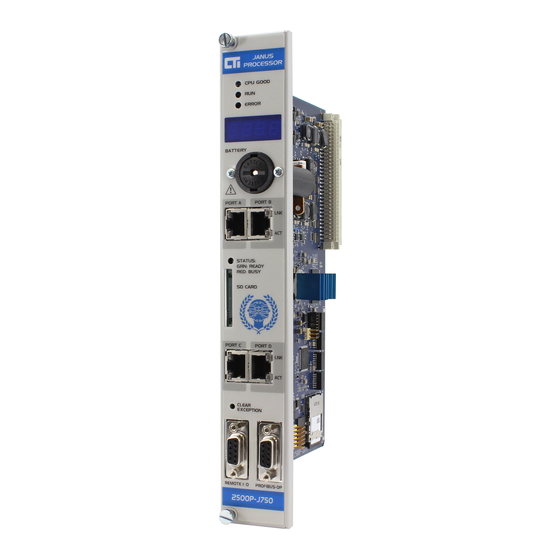
The CTI Janus PAC is an advanced, high-performance IEC-61131-3 compliant PLC with unmatched
integrated communications capabilities and diagnostic features. The processor provides real-time control
functions, connectivity, data handling, and visualization in one product.
Unpacking the Module
Open the shipping carton and remove the special anti-static bag that contains the module. After
discharging any static build-up, remove the module from the static bag. Do not discard the static bag.
Always use this bag for protection against static damage when the module is not inserted into the I/O base.
CAUTION:
The components on the Janus Controller can be damaged by static electricity discharge.
To prevent this damage, the module is shipped in a special anti-static bag. Static control precautions
should be followed when removing the module from the bag and when handling the printed circuit
board during configuration
Installation
The Janus Controller is shipped with the battery and internal SD card installed. The firmware is pre-loaded
on the SD card and ready for operation.
The Janus Controller must be installed into the first slot in the base (next to the power supply).
Remove power from the chassis. Align the circuit board with the connector next to the power supply. Slide
the controller into the rack until the connector seats. Use the thumbscrews to secure the controller to the
rack.
Apply power to the base power supply. The P
G
LED on the power supply should illuminate,
OWER
OOD
indicating that power is being supplied to the base connectors.
CTI Janus Controller Quick Start Guide (P/N 062-000471)
Page 1
Advertisement
Table of Contents

Subscribe to Our Youtube Channel
Related Manuals for CTI JANUS


Summary of Contents for CTI JANUS
- Page 1 SD card and ready for operation. The Janus Controller must be installed into the first slot in the base (next to the power supply). Remove power from the chassis. Align the circuit board with the connector next to the power supply. Slide the controller into the rack until the connector seats.
- Page 2 Your PC should also be able to obtain an IP Address on the same subnet from the DHCP server, and you are ready to connect to the Janus CPU. You must connect an Ethernet cable from your PC directly or via network switch to any of the Janus CPU front panel ports (P...
- Page 3 2) Connect to Janus CPU via Link-Local compatible settings If a DHCP server is not available, the Link Local compatible settings generated by the Janus CPU are displayed on the front panel. Link-Local settings are displayed only when no other network settings have been configured and can be identified as an ‘Auto-IP’...
- Page 4 = 255.255.255.0 gateway = 198.18.74.1 b) Copy the cti.ini file created above to the root directory of a SD card and insert that card into the front panel SD card slot. c) Turn off power to the base, remove the controller from the base, set Module Switch 4 to C...
- Page 5 See Chapter 4 in the Janus Controller Installation and Operation Guide for details on Janus CPU configuration options. CTI Janus Controller Quick Start Guide (P/N 062-000471) Page 5...
- Page 6 Firmware Update Prior to using the Janus Controller, you should verify that the controller firmware is current. The firmware version number displayed in the Product Information page of the embedded web server.
Need help?
Do you have a question about the JANUS and is the answer not in the manual?
Questions and answers