Spirax Sarco FT43 Installation And Maintenance Instructions Manual
Ball float steam traps
Hide thumbs
Also See for FT43:
- Manual (2 pages) ,
- Installation and maintenance instructions manual (28 pages) ,
- Installation and maintenance instructions manual (32 pages)
Advertisement
0667050/6
Installation and Maintenance Instructions
Printed in the UK
IM-S02-30 ST Issue 6
FT43, FT44, FT46 and FT47
Ball Float Steam Traps
1. General
safety information
2. General
product information
3. Installation
4. Commissioning
5. Operation
6. Maintenance
and Spare parts
© Copyright 2002
IM-S02-30
ST Issue 6
1
Advertisement
Table of Contents

Related Manuals for Spirax Sarco FT43


Summary of Contents for Spirax Sarco FT43
- Page 1 0667050/6 IM-S02-30 ST Issue 6 FT43, FT44, FT46 and FT47 Ball Float Steam Traps Installation and Maintenance Instructions 1. General safety information 2. General product information 3. Installation 4. Commissioning 5. Operation 6. Maintenance and Spare parts Printed in the UK IM-S02-30 ST Issue 6 ©...
-
Page 2: General Safety Information
Before attempting any maintenance consider what is or may have been in the pipeline. Ensure that any pressure is isolated and safely vented to atmospheric pressure before attempting to maintain the product, this is easily achieved by fitting Spirax Sarco depressurisation valves type DV (see separate literature for details). Do not assume that the system is depressurised even when a pressure gauge indicates zero. -
Page 3: General Product Information
Note: For additional information see the following Technical Information Sheets: Product Material Section TI reference Capacities DN25 - 50 Cast iron Section 2.2 TI-S02-21 TI-S02-35 FT43 DN80 - 100 Cast iron Section 2.2 TI-S02-22 TI-S02-35 DN15 - 50 Carbon steel Section 2.3 TI-S02-14 TI-S02-36... - Page 4 Flanged JIS /KS 10 (DN25 and 100). DPMX - Maximum differential pressure Size FT43-4.5 FT43-10 FT43-14 DN25 to 100 4.5 bar 10 bar 13 bar Note: The FT43 range of float traps are limited to a PMO equal to DPMX. IM-S02-30 ST Issue 6...
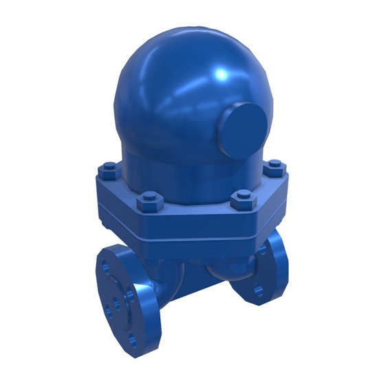
- Page 5 2.3 FT44 - Carbon steel Fig. 2 DN15 shown Sizes and pipe connections Horizontal - DN15, 20, 25, 40, 50, 80 and 100 Vertical - DN15, 20, 25, 40 and 50 Standard flanges are BS 4504 / DIN PN40 with face-to-face dimensions in accordance with EN 26554 (Series 1).
- Page 6 2.4 FT46 - Stainless steel Fig. 3 DN50 shown Sizing and pipe connections DN15, 20, 25, 40 and 50 Standard flanges are BS 4504 / DIN PN40 with face-to-face dimensions in accordance with EN 26554 (Series 1). ANSI B 16.5 Class 150 and 300 flanges are also available with face-to-face dimensions in accordance with EN 26554 (Series 1).
- Page 7 2.5 FT47 - SG iron Fig. 4 DN50 shown Sizing and pipe connections DN15, 20, 25, 40 and 50 Standard flanges are BS 4504 /DIN PN40 /PN25 with face-to-face dimensions in accordance with EN 26554 (Series 1). On request ANSI B 16.5 Class 150 flanges can be supplied with face-to-face dimensions in accordance with EN 26554 (Series 1).
-
Page 8: Installation
3. Installation Note: Before actioning any installation observe the 'Safety information' in Section 1. Warning The cover gasket contains a thin stainless steel support ring, which may cause physical injury if not handled and disposed of carefully. Referring to the Installation and Maintenance Instructions, name-plate, and Technical Information Sheet, check that the product is suitable for its intended use. - Page 9 Float traps should be fitted as close to the outlet of the plant to be drained as possible otherwise the trap can steam lock. Steam locking occurs when the pipe between the condensate outlet and the steam trap fills with steam and prevents condensate from reaching the trap.
- Page 10 If the trap is to be situated in an exposed position, it should be either lagged or drained by a separate small thermostatic trap such as the Spirax Sarco No.8, or Bydrain. Always fit a non-return (check) valve downstream of any steam trap which discharges into condensate return lines where back pressure is experienced.
-
Page 11: Operation
4. Commissioning After installation or maintenance ensure that the system is fully functioning. Carry out tests on any alarms or protective devices. 5. Operation The float trap is a continuous trap, removing condensate the instant it forms. On start-up, the thermostatic air vent allows air to bypass the main valve preventing the system air binding. Hot condensate will close the air vent tightly, but as soon as it enters the main chamber of the trap, the float rises and the lever mechanism attached to it opens the main valve - keeping the system drained of condensate at all times. -
Page 12: Maintenance And Spare Parts
6. Maintenance and Spare parts 6.1 FT43, FT44, FT46 and FT47 (DN15 to 50) Note: Before actioning any maintenance programme observe the 'Safety information' in Section 1. Warning The cover gasket contains a thin stainless steel support ring which may cause physical injury if not handled and disposed of carefully. -
Page 13: Spare Parts
Always order spares by using the description given in the column headed 'Available spares' and state the size, type of trap, connection: horizontal or vertical and pressure range. Example: 1 - Air vent assembly for a DN20 Spirax Sarco FT43 ball float steam trap, with horizontal connectors. - Page 14 6.2 FT43 and FT44 (DN80 and 100) Note: Before actioning any maintenance programme observe the 'Safety information' in Section 1. Warning The cover gasket contains a thin stainless steel support ring which may cause physical injury if not handled and disposed of carefully.
- Page 15 Always order spare parts by using the description given in the column headed 'Available spares' and state the size, Model No. and pressure rating of the trap. Example: 1 - Main valve assembly for a DN80 Spirax Sarco FT43-10TV ball float steam trap. IM-S02-30 ST Issue 6...
- Page 16 6.3 FT mechanisms (DN40 only) Baffle arrangement used on FT43, FT44, FT46 and FT47 (horizontal only) In line with our policy of continuous product improvement, we have found it beneficial to add a baffle plate over the inlet port. This eliminates any risk of flow from the inlet port affecting the correct operation of the float.
Need help?
Do you have a question about the FT43 and is the answer not in the manual?
Questions and answers