Spirax Sarco FT43 Installation And Maintenance Instructions Manual
Ball float steam traps
Hide thumbs
Also See for FT43:
- Manual (2 pages) ,
- Installation and maintenance instructions manual (17 pages) ,
- Installation and maintenance instructions manual (32 pages)
Table of Contents
Advertisement
Quick Links
Advertisement
Table of Contents

Related Manuals for Spirax Sarco FT43


Summary of Contents for Spirax Sarco FT43
- Page 1 IM-IBR17-49IN Issue 1 FT43 and FT44 Ball Float Steam Traps Installation and Maintenance Instructions 1. Safety information 2. General product information 3. Installation 4. Commissioning 5. Operation 6. Maintenance and Spare parts © Copyright 2017 IM-IBR17-49IN Issue 1 Printed in India...
-
Page 2: Safety Information
Determine the correct installation situation and direction of fluid flow. iii) Spirax Sarco products are not intended to withstand external stresses that may be induced by any system to which they are fitted. It is the responsibility of the installer to consider these stresses and take adequate precautions to minimise them. -
Page 3: Pressure Systems
1.9 Tools and consumables Before starting work ensure that you have suitable tools and / or consumables available. Use only genuine Spirax Sarco replacement parts. 1.10 Protective clothing Consider whether you and / or others in the vicinity require any protective clothing to protect against the hazards of, for example, chemicals, high / low temperature, radiation, noise, falling objects, and dangers to eyes and face. -
Page 4: Residual Hazards
Returning products Customers and stockists are reminded that under EC Health, Safety and Environment Law, when returning products to Spirax Sarco they must provide information on any hazards and the precautions to be taken due to contamination residues or mechanical damage which may present a health, safety or environmental risk. - Page 5 Prevention of water hammer Steam trapping on steam mains: 30 - 50 metre intervals Steam Trap set Steam Trap set Trap set Condensate Condensate Condensate Steam Mains - Do's and Don'ts: Flow Flow Steam Steam IM-IBR17-49IN Issue 1...
- Page 6 Prevention of tensile stressing Pipe misalignment: Installing products or re-assembling after maintenance: Do not over tighten. Flange bolts should be gradually tightened across Use correct torque figures. diameters to ensure even load and alignment. Thermal expansion: Guides Axial movement Short Fixing point distance Axial movement...
-
Page 7: General Product Information
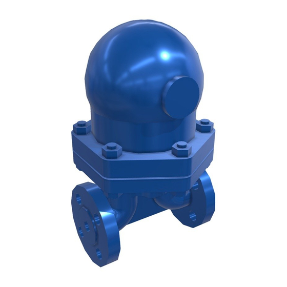
2. General product information 2.1 General description The FT43 - cast iron and FT44 - carbon steel ball float steam traps have stainless steel working internals and automatic built-in air venting facility. These traps are supplied with integrally flanged connections (for horizontal or vertical installations) and can be maintained without disturbing the pipework. - Page 8 Sizes and pipe connections DN25, DN40 and DN50 Note: Flow direction, for FT43 horizontal orientated traps, when facing the body: DN25 is left to right. (R-L versions are available for DN25 FT43TV PN16 only) DN40 and DN50 is right to left.
- Page 9 Note: The DN40 and DN50 traps are limited to a PMO equal to PMX Maximum operating temperature 220 °C @ 12.1 bar g Minimum operating temperature 0 °C Note: For lower operating temperatures consult Spirax Sarco FT43-4.5 4.5 bar FT43-10 DPMX Maximum differential pressure...
- Page 10 2.3 FT44 - Carbon steel FT44 DN15, DN20 and DN25 DN15 shown FT44 DN40 and DN50 DN50 shown FT44-C Fig. 2 Sizes and pipe connections DN15, DN20, DN25, DN40 and DN50 Horizontal traps: Note the flow direction when facing the body is as follows: DN15 to DN25 is left to right.
- Page 11 TMO Maximum operating temperature 300 °C @ 10.2 bar g For lower operating When fitted with a bimetallic air vent temperatures consult Spirax Sarco Cold hydraulic test pressure of : 29.4 bar g For ASME 300 Flange PMA Maximum allowable pressure 40 bar g @ 100 °C...
-
Page 12: Installation
3. Installation Note: Before actioning any installation observe the 'Safety information' in Section 1. Warning The cover gasket contains a thin stainless steel support ring, which may cause physical injury if not handled and disposed of carefully. Referring to the Installation and Maintenance Instructions, name-plate, and Technical Information Sheet, check that the product is suitable for its intended use. - Page 13 Float traps should be fitted as close to the outlet of the plant to be drained as possible otherwise the trap can steam lock. Steam locking occurs when the pipe between the condensate outlet and the steam trap fills with steam and prevents condensate from reaching the trap.
- Page 14 If the trap is to be situated in an exposed position, it should be either lagged or drained by a separate small thermostatic trap such as the Spirax Sarco No.8, or Bydrain. Always fit a non-return (check) valve downstream of any steam trap which discharges into condensate return lines where back pressure is experienced.
-
Page 15: Operation
4. Commissioning After installation or maintenance ensure that the system is fully functioning. Carry out tests on any alarms or protective devices. 5. Operation The float trap is a continuous trap, removing condensate the instant it forms. On start-up, the thermostatic air vent allows air to bypass the main valve preventing the system air binding. -
Page 16: Maintenance And Spare Parts
Notes: Before actioning any maintenance programme observe the 'Safety information' in Section 1. The FT43 is not normally provided with a bimetallic air vent due to its PN16 rating. This arrangement can be made available on request. Steam lock release assembly... - Page 17 Table 1 Recommended tightening torques Item Size (lbf ft) DN15, DN20, 17 A/F M10 x 30 29 - 33 (19 - 24) DN25 DN40 24 A/F M12 x 60 60 - 66 (44 - 48) DN50 24 A/F M16 x 70 80 - 88 (58 - 65) DN15, DN20, 50 - 55...
- Page 18 Servicing: With suitable isolation, repairs can be carried out with the trap in the pipeline. When reassembling, make sure that all joint faces are clean and the dowel locates in the cover. Steam lock release assembly 19 + 21 Dowel Bimetallic air vent assembly 17 How to fit the main valve assembly for DN15, DN20 and DN25: Unscrew the support frame (9), pivot frame (10) and the valve seat (5).
- Page 19 How to fit the main valve assembly for DN40 and DN50: Unscrew the 4 bolts or nuts (7). Remove the main valve assembly (5) and gasket (6). Ensure the gasket faces are clean and dry. Fit the new gasket (6) and the main valve assembly (5), including the baffle plate (see Figures 10 and 11).
-
Page 20: Spare Parts
Spare parts The spare parts available are shown in heavy outline. Parts drawn in a grey line are not supplied as spares. Steam lock release assembly 19 + 21 Dowel Bimetallic air vent assembly 17 IM-IBR17-49IN Issue 1... - Page 21 Assembly, please specify whether you require a bimetallic or capsule air vent assembly. Example: 1 - Capsule air vent assembly for a Spirax Sarco DN20 FT46-4.5 ball float steam trap, with horizontal connectors. Main valve assembly with float (DN15, DN20 and DN25)
- Page 22 Notes: Before actioning any maintenance programme observe the 'Safety information' in Section 1. The FT43 is not normally provided with a bimetallic air vent due to its PN16 rating. This arrangement can be made available on request. Warning The cover gasket contains a thin stainless steel support ring which may cause physical injury if not handled and disposed of carefully.
- Page 23 Table 2 Recommended tightening torques Item No. (lbf ft) 24 A/F M16 x 45 80 - 88 (58 - 65) 13 A/F M8 x 20 20 - 24 (15 - 17) 17 A/F 50 - 55 (37 - 40) Unscrew element assembly Remove the cover nuts (2) and cover.
- Page 24 17, 18 assembly Capsule air vent assembly Example: 1 - Main valve assembly for a DN80 Spirax Sarco FT43-10TV Set of all gaskets (packet of 3 sets) 3, 6, 18 ball float steam trap. Note: For a complete overhaul 2 off of each spare are required.
- Page 25 6.3 FT mechanisms (DN40 only) Baffle arrangement used on FT43 and FT44 (horizontal only) In line with our policy of continuous product improvement, we have found it beneficial to add a baffle plate over the inlet port. This eliminates any risk of flow from the inlet port affecting the correct operation of the float.
- Page 26 IM-IBR17-49IN Issue 1...
- Page 27 IM-IBR17-49IN Issue 1...
- Page 28 IM-IBR17-49IN Issue 1...
Need help?
Do you have a question about the FT43 and is the answer not in the manual?
Questions and answers