Table of Contents
Advertisement
Quick Links
1792050/3
IM-P179-15
CMGT Issue 3
FTC62 and FTS62
Ball Float Steam Traps
Installation and Maintenance Instructions
1. Safety information
2. General product information
3. Installation
4. Commissioning
5. Operation
6. Spare parts and
maintenance
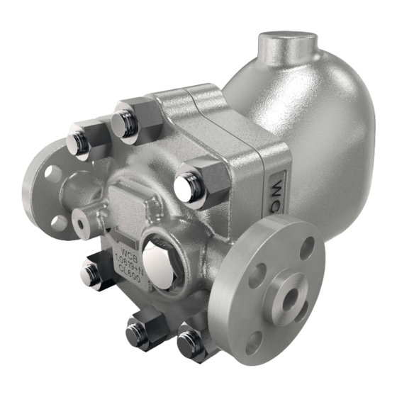
Flanged FT_62 shown
© Copyright 2018
1
IM-P179-15 CMGT Issue 3
Printed in GB
Advertisement
Table of Contents

Subscribe to Our Youtube Channel
Related Manuals for Spirax Sarco FTC62


Summary of Contents for Spirax Sarco FTC62
- Page 1 1792050/3 IM-P179-15 CMGT Issue 3 FTC62 and FTS62 Ball Float Steam Traps Installation and Maintenance Instructions 1. Safety information 2. General product information 3. Installation 4. Commissioning 5. Operation 6. Spare parts and maintenance Flanged FT_62 shown © Copyright 2018...
-
Page 2: Safety Information
Group 2 of the above mentioned Pressure Equipment Directive (PED). The products' use on other fluids may be possible but, if this is contemplated, Spirax Sarco should be contacted to confirm the suitability of the product for the application being considered. -
Page 3: Protective Clothing
1.9 Tools and consumables Before starting work ensure that you have suitable tools and/or consumables available. Use only genuine Spirax Sarco replacement parts. 1.10 Protective clothing Consider whether you and/or others in the vicinity require any protective clothing to protect against the hazards of, for example, chemicals, high/low temperature, radiation, noise, falling objects, and dangers to eyes and face. -
Page 4: Returning Products
Customers and stockists are reminded that under EC Health, Safety and Environment Law, when returning products to Spirax Sarco they must provide information on any hazards and the precautions to be taken due to contamination residues or mechanical damage which may present a health, safety or environmental risk. - Page 5 Prevention of water hammer Steam trapping on steam mains: 30 - 50 metre intervals Steam Trap set Trap set Trap set Steam Condensate Condensate Condensate Steam Mains - Do's and Don'ts Flow Flow Steam Steam IM-P179-15 CMGT Issue 3...
- Page 6 Prevention of tensile stressing Pipe misalignment: Installing products or re-assembling after maintenance: Do not over tighten. Flange bolts should be gradually tightened across Use correct torque figures. diameters to ensure even load and alignment. Thermal expansion: Guides Axial movement Short Fixing point...
-
Page 7: General Product Information
Flanged EN 1092-1 PN100 Please note: For the PN100 variant the material used for the weld on flange is carbon steel 1.0460 for the FTC62 and stainless steel 1.4301 upon the FTS62. The material used for the studs and nuts upon all versions is Studs = ASTM A193 B7 Nuts = ASTM A194 Gr. -
Page 8: Pressure/Temperature Limits
Fig. 1 FT_62 R-L flanged with flow from right to left 2.3 Pressure/temperature limits (ISO 6552) Screwed Section 2.4 Socket weld , page 9 FTC62 Flanged ASME Class 600 Section 2.5 Flanged EN 1092 PN100 , pages 10 Screwed Section 2.6... - Page 9 425 °C @ 57.5 bar g 797 °F @ 834 psi g Minimum operating temperature 0 °C 32 °F Note: For lower operating temperatures consult Spirax Sarco Minimum operating differential pressure 0.1 bar g 1.45 psi g FTC62-46 46 bar...
- Page 10 70.8 bar g @ 287 °C Maximum operating temperature 400 °C @ 59.5 bar g Minimum operating temperature 0 °C Note: For lower operating temperatures consult Spirax Sarco Minimum operating differential pressure 0.1 bar g FTC62-46 46 bar Maximum differential pressure ...
- Page 11 425 °C @ 56 bar g 797 °F @ 812 psi g Minimum operating temperature 0 °C 32 °F Note: For lower operating temperatures consult Spirax Sarco Minimum operating differential pressure 0.1 bar g 1.45 psi g FTS62-46 46 bar...
- Page 12 65.8 bar g @ 283 °C Maximum operating temperature 425 °C @ 58.9 bar g Minimum operating temperature 0 °C Note: For lower operating temperatures consult Spirax Sarco Minimum operating differential pressure 0.1 bar g FTS62-46 46 bar Maximum differential pressure ...
- Page 13 2.8 Flanged - dimensions/weights (approximate) in mm and kg Notes: 1. PN100 EN 1092-1 and ASME 600 B 16.5 face-to-face dimensions Size Flanged Common sizes PN100 ASME 600 Weight Weight DN15 304.0 25.0 24.0 172.5 251.5 DN20 316.5 26.0 25.5 172.5 251.5 DN25...
- Page 14 2.9 Screwed and socket weld - dimensions/weights (approximate) in mm and kg Notes: 1. PN100 EN 1092-1 and ASME 600 B 16.5 face-to-face dimensions Fig. 3 Size Screwed and Socket weld Common sizes Weight DN15 287.5 22.0 172.5 251.5 DN20 287.5 22.0 172.5...
- Page 15 Note: The Air vent closing temperature range = 120 °C to 135 °C For differential pressures less than 1.5 bar g, the additional cold water capacity is minimal. P (bar) FTC62 Minimum additional cold water capacity (kg/h) 46 bar version...
-
Page 16: Installation
If the trap is to be situated in an exposed position, it should be either lagged or drained by a separate small thermostatic trap such as the Spirax Sarco No.8, or Bydrain. Always fit a non-return (check) valve downstream of any steam trap which discharges into condensate return lines where backpressure is experienced. -
Page 17: Operation
4. Commissioning After installation and maintenance ensure that the system is fully functional. Carry out tests on any alarms or protective devices. After installation or maintenance always open isolation valves slowly to mitigate system shocks and check for leaks. Ensure that the system is fully functional and carry out tests on any alarms or protective devices. The trap can be cold hydraulic tested, up to 1.5 times the PMA as per section 2, without the need to remove any internals. -
Page 18: Spare Parts And Maintenance
6. Spare parts and maintenance Note: Before actioning any maintenance observe the 'Safety information' in Section 1. Warning The cover gasket contains a thin stainless steel support ring, which may cause physical injury if not handled and disposed of carefully. Recommended tightening torques inch Item Part... -
Page 19: Spare Parts
Always order spares by using the description given in the column headed 'Available spares' and state the size and type of trap, including pressure range. Example: 1 - Maintenance kit for a Spirax Sarco DN25 FTC62-62 ball float steam trap. IM-P179-15 CMGT Issue 3... -
Page 20: Maintenance
6.2 Maintenance General safety information: With suitable isolation, repairs can be carried out with the trap in the pipeline. When reassembling, make sure that all joint faces are clean. Service being executed upon the valve can be undertaken with the Float in situe in a line or securely fastened in a vice. - Page 21 6.2.1 Pre-assembly of the main valve Holding the lever arm and float vertically with the float downward. Place the conical spring (16) in the box at the end of the lever arm, with the small diameter of the conical spring facing upward, place the ball (15) upon the top of the spring. Insert the pin (13).
- Page 22 6.2.3 Replacing the Air vent assembly Gain access to the internals by removal of the cover (2) by undoing the six ¾" UNF (4) nuts holding the cover in place. Then remove the air vent assembly (9) and the air vent tube (10). Put a little anti-seize on the thread of the new air vent assembly (9) together with the tube (10) preassembled, tighten following the guidance of the torque setting in the table.
- Page 23 6.2.4 How to clean or replace the strainer screen: Access to the strainer screen can be obtained by removing the strainer cap (6). Remove the strainer screen (7) and gasket (8). Fit a new or cleaned strainer screen into the recess in the cap (6). A new gasket (8) must always be fitted and the cap (6) screwed into the body and tighten to the recommended torque (170-190 Nm).
- Page 24 6.2.5 General notes Smear threads (both ends) of the studs (5) and also of items (6), (9) and (12) with with a suitable anti- seize compound, such as FUCHS PCB or ROCOL J166, taking care the compound does not come into contact with any sealing surfaces.
- Page 25 Fig. 5 For Left-to-Right options the body (1) is rotated through 180 ° regardless of flow direction the open end of the air vent tube sub-assembly (10) must always be uppermost. Regardless of flow direction the arrow on the seat clamp (11) must always be pointing upwards.
- Page 26 IM-P179-15 CMGT Issue 3...
Need help?
Do you have a question about the FTC62 and is the answer not in the manual?
Questions and answers