
Related Manuals for NRG Systems Hybrid XT Vane

Summary of Contents for NRG Systems Hybrid XT Vane
- Page 1 Product Manual Hybrid XT Vane Authors: Technical Services HybridXT_Vane_Manual Rev 13.0...
- Page 2 NRG Product Manual Hybrid XT Vane Specifications are subject to change without notice. © NRG Systems 110 Riggs Road Hinesburg VT 05461 Tel: 802-482-2255 Fax: 802-482-2272 e-mail: sales@nrgsystems.com HybridXT_Vane_Manual support@nrgsystems.com | Page 2 Rev 13.0 7 February 2017...
-
Page 3: Table Of Contents
INTRODUCTION .............................. 5 USING THIS MANUAL ............................5 VANE OPERATION AND CONSIDERATIONS ...................... 6 Hybrid XT Vane Head Damping ..................6 CABLES COMPATIBILITY TABLES ........................9 INSTALLATION AND TECHNICAL DRAWINGS ....................11 GROUNDING AND BONDING HYBRID XT™ SENSORS FOR OVER-VOLTAGE PROTECTION ....... 16 WARRANTY &... -
Page 4: Customer Support
CUSTOMER SUPPORT NRG Systems offers a variety of support options to help you get the most from your NRG Systems product. If you have questions about your NRG Systems product, first look in the printed product documentation, the Knowledge Base and the Technical Forum contained in the Tech Support section of the NRG Systems web site. -
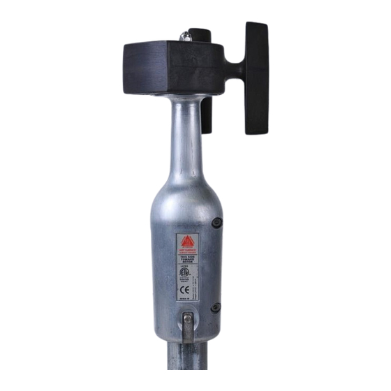
Page 5: Introduction
Hybrid XT Vane INTRODUCTION The NRG Systems Hybrid XT vane is an electrically heated wind direction sensor designed for wind turbine control and wind resource assessment. The sensor is mounted to the turbine nacelle or meteorological mast and provides an electrical output signal relative to wind direction. -
Page 6: Vane Operation And Considerations
Hybrid XT Vane Head Damping The Hybrid XT Vane has damping in the head to reduce overshoot and oscillation behind the turbine rotor. One result of this is that the frequency response has been lowered slightly. This may, in some limited circumstances, require a slight adjustment to the turbine controller settings when retrofitting a Hybrid XT in place of an IceFree 2, IceFree 3, or an original Hybrid. - Page 7 NRG Product Manual Hybrid XT Vane Heater Operation The heat source for the Hybrid XT is a self-regulating, constant-temperature heater. Constant heating prevents condensation and corrosion and maintains proper bearing temperature for consistent performance and transfer function. In severe wind and icing conditions, the Hybrid XT draws more power to help remain clear of ice. As conditions improve, the Hybrid XT draws less power.
- Page 8 On the NRG Systems -cable assembly for the Hybrid XT Turbine Control Sensor, the shield is available for connection at both ends. If the sensor end is not to be connected, cut off the shield wire at the sensor end before installation to prevent accidental contact to the sensor mount.
-
Page 9: Cables Compatibility Tables
NRG Product Manual Hybrid XT Vane CABLES COMPATIBILITY TABLES There have been several different versions of the Hybrid cable assembly since inception to accommodate various sensor and turbine configurations. Please see the tables below to verify cable compatibility. Hybrid Turbine Control Sensor Cables... - Page 10 Output Turbine Control 8797 may be used, Yellow (Out 2) is not used 8115 Sensor, Anem and may be left disconnected Hybrid XT Vane, 4-20mA 4716, 4717, 8797, Any cable may be used; if present, Yellow (Out Output, Counter Clockwise 9234, 9319...
-
Page 11: Installation And Technical Drawings
NRG Product Manual Hybrid XT Vane INSTALLATION AND TECHNICAL DRAWINGS Mounting Mast Orientation Refer to the technical drawing for details on mounting mast design. Orient the cross-holes in the top of the mounting mast such that they are lined up parallel to the turbine nacelle centerline. - Page 12 NRG Product Manual Hybrid XT Vane Mount Connector Remove the nut, washer, and bolt from the connector. Feed the cable through the mounting mast until the connector reaches the mast. Align the bolt hole in the connecter with the holes in the mounting mast such that the “TOWARD ROTOR”...
- Page 13 NRG Product Manual Hybrid XT Vane The Hybrid XT sensors have four ridges running vertically inside the body's lower end as shown in the picture below. These ensure that the sensor mounts securely on the mounting mast. If attaching the shield to the ground screw, make sure that it does not interfere with the mounting ridges by running it straight down the mast from the connector to the ground screw.
- Page 14 There will be some drag as the o-ring seal and the connector pins engage. Tighten the bolt using a 10 mm wrench to 7 N-m (5 ft-lbs). Replacement washers, nuts and bolts can be ordered from NRG Systems (part #4422).
- Page 15 NRG Product Manual Hybrid XT Vane Technical Drawing HybridXT_Vane_Manual support@nrgsystems.com | Page 15 Rev 13.0 7 February 2017...
-
Page 16: Grounding And Bonding Hybrid Xt™ Sensors For Over-Voltage Protection
PROTECTION Introduction The purpose of this document is to outline NRG Systems’ recommended practices for wiring, grounding, and bonding of Hybrid XT™ turbine control sensors. The goal is to provide the best possible protection against direct and indirect lightning damage for both the sensor and the interconnected turbine systems. - Page 17 NRG Product Manual Hybrid XT Vane about preventing ground loops. NRG Systems supplied cables provide a shield at the sensor end. If your LPS design does not use this shield drain, trim it off to prevent short circuits. 5. Run the sensor cabling in metallic raceway or conduit. Bond the raceway or conduit to the LPS at both ends.
- Page 18 NRG Product Manual Hybrid XT Vane Overvoltage protection of D.C. Power and Output returned to D.C. Ground Sensor Body is bonded to mounting mast by mounting hardware Mounting mast must be bonded to the turbine lightning protection system Pin 3: (red) D.C. Power to Sensor Pin 4: (white) Output Signal Pin 6: (black) D.C.
-
Page 19: Warranty & Repair
Hybrid XT Vane WARRANTY & REPAIR NRG Systems (NRG) warrants its products for a period of two years from date of original purchase solely for the benefit of the original consumer purchaser. If this product is determined to be defective in materials or workmanship, NRG will, at NRG’s option, repair or replace this product without charge. -
Page 20: Sending Items For Repair
Hybrid XT Vane SENDING ITEMS FOR REPAIR INTERNATIONAL CUSTOMERS Contact NRG Systems by phone, email, or through our website to obtain an RMA number (Return Material Authorization). Write the RMA number clearly on all shipping cartons. Tel: 802-482-2255 Fax: 802-482-2272 email: support@nrgsystems.com... - Page 21 US CUSTOMERS Please see items 1, 4, and 5 above. Send your item(s) to NRG Systems “Freight Prepaid and Insured.” Shipments sent freight collect will not be accepted by NRG Systems. NRG Systems...
-
Page 22: Declaration Of Conformity
DECLARATION OF CONFORMITY... -
Page 23: Appendix A: Fg# 4715 - Hybrid Xt Turbine Control Vane
If you were to look at the signal on an oscilloscope, you would notice that the rising edges fluctuate back and forth from cycle to cycle. This is normal and was designed this way for Renewable NRG Systems factory use. This will not affect your frequency counter in any way. -
Page 24: Appendix B: Fg# 5762 - Hybrid Xt 4-20 Ma Output Vane
NRG Product Manual Hybrid XT Vane APPENDIX B: FG# 5762 – HYBRID XT 4-20 MA OUTPUT VANE Output Circuit Operation The Hybrid XT 4-20 mA Turbine Control Vane provides an industry standard 4 to 20 mA output signal sourced by the sensor. -
Page 25: Appendix C: Fg# 7894 - Hybrid Xt Push-Pull Vane
Output Circuit Operation The Model 7894 Push-Pull Hybrid XT vane was designed as a direct replacement for 1- or 2-Channel NPN-type IceFree3™ wind vanes. It provides two output signals, in push-pull format. These outputs can source current when on and sink current when off for compatibility with a wide range of controller inputs, including those designed for existing NPN or PNP sensors. - Page 26 NRG Product Manual Hybrid XT Vane dithered signal is switching on and off with a ratio of 50%. As the wind varies to the right or left, the sensor varies the on/off ratio to simulate an under-damped vane’s mechanical dithering.
-
Page 27: Appendix D: Fg# 9362 - Hybrid Xt 4-20Ma, Counter-Clockwise Vane
The Hybrid XT 4-20 mA Turbine Control Vane provides an industry standard 4 to 20 mA output signal sourced by the sensor. The output range of 4 to 20 mA corresponds to 0 to 360 degrees. The output of this Hybrid XT vane increases from 4-20mA proportionally as the sensor swings in a counter-clockwise rotation, opposite the FG #5762 version. -
Page 28: Appendix E: Fg# 9363 - Hybrid Xt Push-Pull, Active-High Vane
Output Circuit Operation The Model 9363 Push-Pull Hybrid XT vane was designed as a direct replacement for 1- or 2-Channel PNP-type IceFree3™ wind vanes. It provides two output signals, in push-pull format. These outputs can source current when on and sink current when off for compatibility with a wide range of controller inputs, including those designed for existing NPN or PNP sensors. - Page 29 The Hybrid XT turbine control vane head maintains a stable output position that tracks the wind direction more accurately and varies much less than under-damped sensors. For compatibility with controllers that are expecting a dithered signal, the electronics of the Model 7894 Push-Pull Hybrid XT Vane creates a compatible dithered signal. When the XT senses the...
Need help?
Do you have a question about the Hybrid XT Vane and is the answer not in the manual?
Questions and answers