
Related Manuals for Big Lift Big Joe PDC Series


Summary of Contents for Big Lift Big Joe PDC Series
- Page 1 PDC SERIES POWER DRIVEN COUNTERBALANCED LIFT TRUCK Serial Number 384041 and Higher Operation Maintenance Repair Parts List Big Lift LLC MANUAL NO. 902997 www.bigjoeforklifts.com 02/05/2014...
-
Page 3: Table Of Contents
TABLE OF CONTENTS Section Page Section Page DESCRIPTION ............1-1 8 ELEVATION SYSTEM SERVICING ......8-1 8-1. GENERAL............8-1 1-1. INTRODUCTION..........1-1 LIFT CHAIN ADJUSTMENT 1-2. GENERAL DESCRIPTION.......1-1 8-2. 1-3. SAFETY FEATURES........1-1 (NON-TELESCOPIC, AND TELESCOPIC) ..8-1 LIFT CHAIN ADJUSTMENT 1-4. - Page 4 TABLE OF CONTENTS - Continued Section Page Section Page 11 OPTIONAL EQUIPMENT ......... 11-1 11-4. HAND HELD REMOTE CONTROL....11-1 11-1. KEYSWITCH..........11-1 11-5. AUXILIARY HYDRAULICS ......11-1 11-2. HOUR METER..........11-1 12 ILLUSTRATED PARTS BREAKDOWN ....12-1 11-3. BATTERY CAPACITY INDICATOR....11-1 LIST OF ILLUSTRATION Figure Page...
- Page 5 LIST OF ILLUSTRATION - Continued Figure Page Figure Page 12-34 LIFT CYLINDER ASSEMBLY 12-44 CONTROL PANEL ASSEMBLY (TYPE EE)... 12-78 (FULL FREE LIFT) .......... 12-66 12-45 CONTROL PANEL ASSEMBLY (TYPE E) ..12-80 12-35 SECONDARY LIFT CYLINDER (2 INCH) 12-46 CONTROL PANEL ASSEMBLY (TYPE EE)...
- Page 6 NOTES 902997...
- Page 7 902997...
- Page 8 902997...
- Page 9 902997...
- Page 10 902997...
- Page 11 OPERATOR INSTRUCTIONS WARNING Do not operate this truck unless you have been trained Do not overload truck. Check capacity plate for load and authorized to do so and have read all warnings weight and load center information. and instructions in operator's manual and on this truck. When using forks, space forks as far apart as load will Do not operate this truck until you have checked its permit.
- Page 12 NOTES 902997...
-
Page 13: Description
SECTION 1 DESCRIPTION 1-1. INTRODUCTION. This publication describes the Big Joe Power Driven Counterbalanced (PDC) lift truck manufactured by Big Lift, LLC. Included are operating instructions, planned maintenance instructions, lubrication procedures, cor- rective maintenance procedures and a complete parts list with By following the recommendations contained in this manual, you will receive many years of depend- able service from your Big Joe lift truck. -
Page 14: Options And Accessories
IMPORTANT:This heading calls attention to a proce- 1-4. OPTIONS AND ACCESSORIES. dure, which if not followed, may impede Big Lift offers many options and accessories for the the operation or normal flow of a servic- PDC lift truck such as: ing or repair procedure. -
Page 15: Pdc Lift Truck
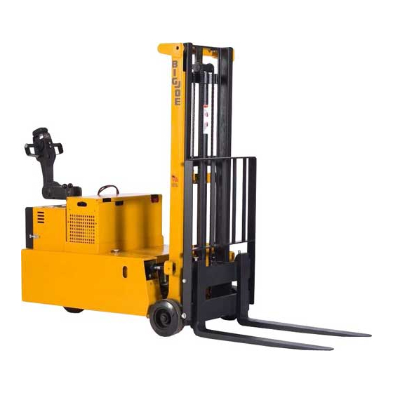
MAST LIFT CYLINDER LIFT CARRIAGE TILT CYLINDER BASE AND FRAME R5378 Figure 1-2 PDC Lift Truck 902997... - Page 16 NOTES 902997...
-
Page 17: Operation
SECTION 2 OPERATION 2-1. GENERAL. Do not handle unstable or loosely stacked loads. Use special care when handling long, high, or This section gives detailed operating instructions for wide loads to avoid tipping, loss of load, or striking the PDC lift truck. The instructions are divided into the bystanders. -
Page 18: Before Operation
12. Operate truck only from a walking position. Never WARNING: Period maintenance of this truck by a place any part of your body between the mast QUALIFIED TECHNICIAN is required. uprights. Do not carry passengers. CAUTION: A QUALIFIED SERVICE TECHNICIAN 13. -
Page 19: Sample Of Operator Check List
Electric Truck Daily Operator Check-Off List Big Joe Manufacturing Company Date Operator Truck No. Model No. Dept. Shift Hour Meter Reading Drive Hoist Check O.K. ( ) Need Maintenance Tires Lights Horn Lift Lower Control Tilt Control Attachment Operation Drive Control Steering Service Brakes Parking Brake... -
Page 20: Instruments And Controls
2-4. INSTRUMENTS AND CONTROLS Table 2-2 Control Handles Type Part Numbers 2-4.1. Steering Arm and Control Head. Standard 505360-01 The steering arm and control handle (See Figure 2-3) Remote Lift in Handle 505360-02 provide controls for steering, forward and reverse Remote Lift and Lower in Handle 505360-03 speed control, braking, and horn. -
Page 21: 2-4.2. Lift/Lower And Tilt Control
2-4.2. Lift/Lower and Tilt Control. All models come standard with a lift/lower control lever and a tilt control lever mounted near the steering arm. Figure 2-4. LIFT/LOWER CONTROL 2-4.3. Battery Disconnect. LEVER A battery disconnect is mounted near the steering TILT arm. -
Page 22: 2-5.3. Stopping
2-5.3. Stopping. event the driver releases the control handle during operation. This is known as deadman brak- Stop the truck as gradually as possible. Unnecessary ing. rapid stopping could be hazardous. Load could Dynamic Brake: The dynamic brake serves as a become unstable. -
Page 23: 2-5.5. Battery Charging
2-5.5. Battery Charging Make sure the load is against the backrest and then raise the forks until the pallet clears the rack. Refer to Document 245 for battery safety and Tilt the forks slightly backward. maintenance. Move the truck away from the rack until the load clears the rack and then lower the forks. - Page 24 NOTES 901349...
-
Page 25: Planned Maintenance
These proce- dures must be performed by a qualified service technician or your Big Lift/Big Joe service representa- R4864 tive. The battery cells are accessed by opening the top cover of the battery. -
Page 26: Lubrication
NOTE: Battery specific gravity readings should agree Table 3-2 Recommended Lubricants and Oils. within + 0.025 from cell to cell. If variation is No. 1 Transmission oil—EP SAE 80W-90 greater, the battery may have to be repaired Transmission oil—EP SAE 10W-30 (Note) or replaced. -
Page 27: Lubrication Diagram
R5380 Figure 3-1 Lubrication Diagram Table 3-4 Lubrication Chart FIG 3-1 LOCATION METHOD OF TYPE APPLICATION INDEX APPLICATION (Table 3-3) LUBRICANT Lift carriage rollers No. 2 Pressure lubricate. Tilt cylinder mounts No. 2 Pressure lubricate both ends of each cylinder. Outer and inner masts Brush No. - Page 28 NOTES 902997...
-
Page 29: Troubleshooting
SECTION 4 TROUBLESHOOTING 4-1. GENERAL Table 4-1 serves as a guide to determine possible 1. SEE SUPPLEMENT 345 FOR PDC-20A, causes of trouble. The table is divided into five main PDC-20, PDC-25, PDC-30 ADDITIONAL categories: Truck Dead: Trouble With Travel: Trouble TROUBLESHOOTING INFORMATION. - Page 30 Table 4-1 Troubleshooting Chart - Continued MALFUNCTION PROBABLE CAUSE CORRECTIVE ACTION TROUBLE WITH TRAVEL (CONT.) Truck runs in reverse but nor for- Defective speed control switch or Check for positive DC voltage at ward. defective contactor number 2-wire on forward con- tactor.
- Page 31 Table 4-1 Troubleshooting Chart - Continued MALFUNCTION PROBABLE CAUSE CORRECTIVE ACTION TROUBLE WITH LIFTING OR LOWERING (CONT.) Forks creep downward under load Leak in hydraulic system, packing, Look for loose fittings in the or when unit is not in use, every- control valve or pump.
- Page 32 Table 4-1 Troubleshooting Chart - Continued MALFUNCTION PROBABLE CAUSE CORRECTIVE ACTION MISCELLANEOUS (CONT.) Truck moves forward in low speed a. Belly-button reversing switch Check for short, and repair or when arm is pulled down. defective. replace as necessary. b. Forward contactor stuck closed. Repair or replace.
- Page 33 NOTES 902997...
-
Page 34: Drive Motor
PDC-15, PDC-20, PDC-25 & PDC-30 TYPE E & EE 300 A 15 A OVERRIDE LIFT LIMIT KEYSWITCH DRIVE MOTOR ARMATURE DRIVE MOTOR FIELD PUMP MOTOR SOLID STATE CONTROL NOTES: 1. SYMBOLS: F = FORWARD CONTACTOR R = REVERSE CONTACTOR P = PUMP SOLENOID L = REMOTE LOWERING (OPT) RS = REMOTE LIFT (OPT) - Page 35 PDC-15, PDC-20, PDC-25 & PDC-30 TYPE E & EE DEADMAN N.O. N.C. CONTROL HEAD 5K SPEED CONTROL POTENTIOMETER HORN REMOTE REMOTE LIFT LOWER TRAVEL SPEED LIMIT SWITCH N.C. N.O. NOTES: 1. SYMBOLS: F = FORWARD CONTACTOR R = REVERSE CONTACTOR P = PUMP SOLENOID L = REMOTE LOWERING (OPT) RS = REMOTE LIFT (OPT)
-
Page 36: Electrical Schematic
PDC-40 TYPE E & EE R7078A Figure 4-2 Electrical Schematic (Sheet 1) 902997... - Page 37 PDC-40 TYPE E & EE R7078B Figure 4-2 Electrical Schematic (Sheet 2) 902997...
-
Page 38: Wiring Diagram
PDC-15, PDC-20, PDC-25 & PDC-30 TYPE E BATTERY DRIVE MOTOR CONNECTOR KEYSWITCH HOUR DIODE METER ASSY MAST SWITCH ON C.V. TRI 300 AMP & C.V. FFL TERMINAL BOARD ON TRANS 16 15 14 13 12 11 10 13 14 REMOTE LOWERING SOLENOID... - Page 39 PDC-15, PDC-20, PDC-25 & PDC-30 TYPE E 5K SPEED CONTROL POTENTIOMETER 1.2K HORN REVERSING LIFT LOWER COLD CONDITIONING 1 2 3 4 5 6 7 8 9 101112131415 CONTROL HEAD DEADMAN SWITCH C.V. FFL & C.V. TRI MAST STAGING VALVES STAGE STAGE &...
-
Page 40: Wiring Diagram
PDC-15, PDC-20, PDC-25 & PDC-30 TYPE EE BATTERY DRIVE MOTOR CONNECTOR KEYSWITCH HOUR DIODE METER ASSY MAST SWITCH C.V. TRIMAST TERMINAL REMOTE BOARD LOWERING ON TRANS SOLENOID 16151413121110 9 8 7 6 5 4 3 2 1 B- B+ LIFT LIMIT SWITCH... - Page 41 PDC-15, PDC-20, PDC-25 & PDC-30 TYPE EE 5K SPEED CONTROL POTENTIOMETER 1.2 K HORN REVERSING COM NO LIFT COM NO LOWER COLD CONDITIONING COM NO 1112 1415 CONTROL HEAD DEADMAN SWITCH CLEAR VIEW TRIMAST MAST STAGING VALVES STAGE STAGE &...
- Page 42 PDC-40 TYPE E R7079A Figure 4-5 Wiring Diagram (Sheet 1) 4-14 902997...
- Page 43 PDC-40 TYPE E R7079B Figure 4-5 Wiring Diagram (Sheet 2) 902997 4-15...
- Page 44 PDC-40 TYPE EE R7080A Figure 4-6 Wiring Diagram (Sheet 1) 4-16 902997...
- Page 45 PDC-40 TYPE EE R7080 Figure 4-6 Wiring Diagram (Sheet 2) 902997 4-17...
- Page 46 NOTES 4-18 902997...
-
Page 47: Steering Arm And Control Head Servicing
SECTION 5 STEERING ARM AND CONTROL HEAD SERVICING 5-1. GENERAL. The following procedures cover adjustments, replace- ment, and repair of the steering arm, control head, and related assemblies and components. The procedures are independent of each other unless specifically referenced. Speed controls are located on the inner hand grips. -
Page 48: Potentiometer Testing And Adjust- Ment
5-3. BELLY-BUTTON SWITCH ADJUSTMENT. NOTE: All electrical connections should be tagged with identifying labels before disconnecting. Disconnect battery and electrical connections. CAUTION: While removing the belly-button casting, two springs (needed for reassembly) will fall free. Being careful to catch and retain the belly-button springs (33, Figure 5-5) that may fall from the con-... -
Page 49: Control Head Switch Replacement
same as for the forward direction (± 200 ohms). If 5-6) and/or switch plate (16) must be meter readings are not the same, adjust position removed. of bracket (44, Figure 5-5) as necessary to obtain NOTE: All electrical connections should be tagged the same values. -
Page 50: Control Head Assembly
Figure 5-6 FOR SWITCHS Figure 12-3 FOR COLD CONDITIONING R6089 Figure 5-5 Control Head Assembly 902997... -
Page 51: Speed Control Switch And Return Spring Replacement
PDC WITH HORN AND BRAKET PDC WITH LIFT ONLY 505360-01, 02 & 03 (STANDARD) 505360-02 (OPTION) R7040 PDC WITH LIFT AND LOWER R7041 505360-03 (OPTION) 505360-01 (STAN- DARD) R7043 R7042 Figure 5-6 Push Button Switches, Control Head 5-6. -
Page 52: Steering Arm Return Spring Adjustment
16. Install right hand control lever (52) onto tube (45), Check the spring action by lowering the steering and secure with set screw (30). arm and returning it to the upright position two or three times. 17. Install right hand handle grip (41) onto shaft (38), align roll pin hole in handle grip with roll pin hole in If necessary, repeat steps through 6., increas-... -
Page 53: Pivot Tube Replacement
HANDLE RETURN SPRING KIT 901325 CONTAINS: QTY ITEM 1 1 2 2 1 R5994 Figure 5-7 Steering Arm Lubricate the ends and outer surface of the new 14. Adjust tension on steering arm return spring as steering arm return spring (5) with a lithium base explained in paragraph 5-7. -
Page 54: Replacement
Remove pivot cap with electrical control cable, 17. Attach hoist chain to pivot tube as described in steering arm and control head from pivot tube step assembly. 18. Install the pivot tube (7) through the bottom of the Remove spacer (1) from the pivot tube. truck and position a support under pivot tube. -
Page 55: Replacement
1 CABLE CLAMP 2 CABLE CLAMP 3 SPRING TUBE ASSEMBLY 4 ELECTRICAL CONTROL CABLE 5 PIVOT CAP 6 PIVOT CAP COVER 7 CAP SCREWS 8 FEMALE CONNECTOR 9 TERMINAL BOARD 10 PIVOT TUBE 11 TRANSMISSION HOUSING R5150 R962,R963 Figure 5-9 Pivot Tube Bushing Replacement Figure 5-10 Electrical Control Cable Replacement NOTE : The dead-man switch is on the brake linkage. - Page 56 the dead-man switch. Cable wire number 3 is CAUTION: Improper cable loop adjustment while connected to the other lead on the dead-man performing the following step will dam- switch. age the cable. If too tight, the cable will tear when the steering arm is in the up Remove base access cover, and disconnect ter- position.
-
Page 57: Brake Servicing
SECTION 6 BRAKE SERVICING 6-1. ADJUSTMENT Securely block the truck to prevent slipping, then jack up the truck so the drive wheel is off the If the mechanical brake does not begin to hold when ground. the steering arm is raised or lowered into the lightly Remove base access cover. -
Page 58: Replacement Of Brake Pads
Remove the cotter pin (1, Figure 6-2), and pin (2) to disconnect the clevis (3) from the lever assem- bly. Loosen the lock nut (4). Turn the clevis (3) to adjust the brake. Connect the clevis (3) to the lever assembly with pin (2), but do not insert the cotter pin (1) at this time. -
Page 59: Brake And Linkage
10. Discard the springs (32 and 36) and brake pads 15. Assemble the two lock washers (29) and nuts (28) (33 and 37). Replace them with new parts. to the bolts (30). 11. Assemble the washer (40), lever (39), bracket 16. -
Page 60: 6-2.1. Replacement Of Brake Disc
6-2.1. Replacement of Brake Disc. 11. Install new disc assembly with key (18), lock washer (20) and nut (21). Disconnect the battery. 12. Assemble the brake pad (33), springs (32), and Block the wheels to prevent the truck from rolling. spacers (31) to the two bolts (30). -
Page 61: Transmission, Drive Wheel And Load Wheel Servicing
SECTION 7 TRANSMISSION, DRIVE WHEEL AND LOAD WHEEL SERVICING Completing the initial disassembly procedure provides Disconnect the mechanical brake by removing access to any transmission parts requiring replace- cotter pin (1, Figure 7-2) clevis pin (2) that ment. secures the rod clevis to the lower lever assembly (3). -
Page 62: Transmission Removal
R7092 Figure 7-2 Transmission Removal 13. Remove the transmission and drive wheel (9) 21. Remove drive wheel and axle shaft (1) to free from the truck by raising the rear of the lift truck gear (6), roller bearing cones (3) and cups (4), with jacks or other suitable means and sliding the and oil seal (2). -
Page 63: Drive Wheel Replacement
7-2. DRIVE WHEEL REPLACEMENT end is lowered it will remain about 6 inches off the floor and the load wheel will not touch the floor. Disconnect battery. Lower the lift truck onto the support. Securely block the load wheels to prevent the Remove dust cap (10, Figure 7-3). - Page 64 NOTES 902997...
-
Page 65: Elevation System Servicing
SECTION 8 ELEVATION SYSTEM SERVICING 8-1. GENERAL Disconnect the battery. Loosen nut (29) on chain adjusting bolt (28) on The elevation system includes the mast, lift chains, lift the lift carriage. cylinder, ram head and tilt cylinders. Take up slack by tightening nut (31). 8-2. -
Page 66: Lift Chain Adjustment (Full Free Lift)
Test chain by operating carriage. If slack is still Take up slack by tightening nut (23). apparent repeat above procedure. CAUTION: At least 3 full threads must be present below hex nut after completion of adjust- 8-3. LIFT CHAIN ADJUSTMENT (FULL FREE LIFT) ment. -
Page 67: Lift Chain Adjustment (Clear View Tri- Mast)
8-4. LIFT CHAIN ADJUSTMENT (CLEAR VIEW TRI- 8-4.2. Secondary Lift Chains (36, Figure 8-3) MAST) WARNING: Before attempting any adjustment make certain power is disconnected. 8-4.1. Full Free Lift Chain (37, Figure 8-3) Fully lower the lift carriage. WARNING: Before attempting any adjustment make certain power is disconnected. -
Page 68: Lift Chain Inspection
8-5. LIFT CHAIN INSPECTION Lower lift carriage until it is supported by the block and the load chains are slack, then disconnect All chains should be replaced when any of the chains battery. are worn enough to increase it’s length by 3% or more. To make this determination proceed as follows. -
Page 69: Lift Cylinder Replacement
Lower inner mast until it is supported by the block CAUTION: Hold lift cylinder securely during the final and the load chains are slack, then disconnect stages of this procedure. battery. 12. Remove screw (3) and washers (1 and 2) from WARNING: Before attempting any actual replace- bottom of lift cylinder. -
Page 70: Lift Cylinder Replacement
8-11.LIFT CYLINDER REPLACEMENT (CLEAR Disconnect the tube, connector, regulator, reducer VIEW TRIMAST) and elbow from the bottom of the secondary lift cylinder (34). 8-11.1. Full Free Lift Cylinder (35, Figure 8-3) Remove screw and lock washer (11) from the bot- tom of the secondary lift cylinder. -
Page 71: Hydraulic System
PDC 20A, PDC 20, PDC 25, PDC 30 SHOWN ALL OTHER NON TEL, TEL & FLL TRUCKS SIMILAR R2026M Figure 8-4 Hydraulic System 902997... - Page 72 PDC 20, PDC 25, PDC 30 CLEAR VIEW TRIMAST SHOWN PDC 40 CLEAR VIEW TRIMAST TRUCKS SIMILAR TILT CYLINDER TANK SPOOL (RETURN) VALVE TILT BACK PUMP PRESSURE PORT TILT FORWARD STAGING 36 2 VALVE ASSY SPOOL VALVE 17,18 REG.
- Page 73 PDC 20, PDC 25, PDC 30 CLEAR VIEW TRIMAST SHOWN PDC 40 CLEAR VIEW TRIMAST TRUCKS SIMILAR INNER MAST MANIFOLD COVER CABLE W/ ELEC TAPE UNDER CLAMP REG. FLOW MAST SHEAVE TRAVEL SPEED LIMIT SWITCH STAGING VALVES MAST SHEAVE 81 82 COVER CABLE...
-
Page 74: Mast Removal
8-13.HOSE BRACKET REPLACEMENT. WARNING: Before disconnecting any hydraulic lines, make certain the system is not under The hose bracket holds the hose lines to prevent them pressure. Refer to paragraph 9-1. from rubbing on the frame. Disconnect the hydraulic hoses form the lift WARNING: Before disconnecting any hydraulic lines, cylinder. - Page 75 PDC 20A, PDC 20, PDC 25, PDC 30 FULL FREE LIFT SHOWN PDC 40 FULL FREE LIFT SIMILAR R1343M Figure 8-6 Inner and Outer Masts (Full Free Lift) 902997 8-11...
- Page 76 R1342M Figure 8-7 Base and Frame 8-12 902997...
-
Page 77: Hydraulic System Servicing
SECTION 9 HYDRAULIC SYSTEM SERVICING 9-1. RELIEVING SYSTEM PRESSURE. line between the pump and the reservoir will sometimes cause hydraulic oil to foam WARNING: Hydraulic system pressure must be through the vent. relieved before removing hydraulic sys- tem components. Use the following pro- WARNING: Before disconnecting any hydraulic lines, cedure to relieve system pressure: make certain the system is not under... - Page 78 PDC-20A PDC-20 SEE SUPPLEMENT 269 FOR PDC-25 OPTIONAL AUXILIARY PDC-30 HYDRAULICS R2026M Figure 9-1. Hydraulic System (Non-Telescopic and Telescopic) 902997...
- Page 79 PDC-40 SEE SUPPLEMENT 269 FOR OPTIONAL AUXILIARY HYDRAULICS R2027M Figure 9-2 Hydraulic System (Non-Telescopic and Telescopic) 902997...
-
Page 80: Hydraulic System (Ffl)
PDC-20 PDC-25 SEE SUPPLEMENT 269 FOR PDC-30 OPTIONAL AUXILIARY HYDRAULICS R2028M Figure 9-3 Hydraulic System (FFL) 902997... - Page 81 PDC-40 SEE SUPPLEMENT 269 FOR OPTIONAL AUXILIARY HYDRAULICS R2029M Figure 9-4 Hydraulic System (FFL) 902997...
- Page 82 PDC-20 PDC-25 PDC-30 TILT CYLINDER TANK SPOOL (RETURN) VALVE TILT BACK PUMP PRESSURE PORT TILT FORWARD STAGING 36 2 VALVE ASSY SPOOL VALVE 17,18 REG. FLOW ELEC PANEL PUMP MTR NEG MAST SWITCH R6925A Figure 9-5 Hydraulic System (Clear View TRIMAST) (Sheet 1) 902997...
- Page 83 PDC-20 PDC-25 PDC-30 INNER MAST MANIFOLD COVER CABLE W/ ELEC TAPE UNDER CLAMP REG. FLOW MAST SHEAVE TRAVEL SPEED LIMIT SWITCH STAGING VALVES MAST SHEAVE 81 82 COVER CABLE W/ ELEC TAPE UNDER CLAMP INNERMAST WIRING DETAIL CYLINDER SWITCH & TRAVEL SPEED SWITCH ROUTE ITEM 77 CABEL THRU CYL...
-
Page 84: Hydraulic System
PDC-40 TILT CYLINDER 16 50 SPOOL TANK VALVE TILT BACK PUMP TILT PRESSURE FORWARD PORT STAGING VALVE ASSY 36 3 38 34 SPOOL VALVE REG. FLOW ELEC PANEL PUMP MTR NEG MAST SWITCH R6926A Figure 9-6 Hydraulic System (Sheet 1) 902997... - Page 85 PDC-40 INNER MAST MANIFOLD COVER CABLE W/ ELEC TAPE UNDER CLAMP REG. FLOW MAST SHEAVE TRAVEL SPEED LIMIT SWITCH STAGING VALVES MAST SHEAVE COVER CABLE W/ ELEC TAPE UNDER CLAMP INNERMAST WIRING DETAIL CYLINDER SWITCH & TRAVEL SPEED SWITCH ROUTE ITEM 77 CABEL THRU CYL RETAINING STRAP PULL LOOPED HOSE AWAY FROM...
-
Page 86: Filter Replacement
9-3. FILTER REPLACEMENT. Clean the drain plug thoroughly. Reinstall the drain plug. 9-3.1. Sump Filter. NOTE: Refill only with Big Joe hydraulic oil, and only WARNING: Before disconnecting any hydraulic lines, while the lift carriage is completely lowered. make certain the system is not under Refill until oil is to the “FULL”... -
Page 87: Hydraulic Pump And Motor Assembly
9-4. HYDRAULIC PUMP AND MOTOR ASSEMBLY If the pump is defective, install a new pump. If motor is defective, a new motor may be installed, WARNING: Before disconnecting any hydraulic lines, or motor may be rebuilt (see SECTION 10). make certain the system is not under Reinstall assembly in truck and connect hydraulic pressure. -
Page 88: Control Valve Replacement
9-5. CONTROL VALVE REPLACEMENT Remove pivot pin (9) and spacer (7) that attach control levers (5 and 6) to truck body. WARNING: Before disconnecting any hydraulic lines, Disconnect levers (5 and 6) from valve by remov- make certain the system is not under ing clevis pins (13). -
Page 89: Flow Control Valve Replacement (Non-Telescopic And Telescopic)
10. Attach control levers (5 and 6) to truck body with Remove reducers (49) from flow control valve pivot pin (9) and spacer (7). (50) and install them in the new flow control valve. 11. Connect the wires and hoses to the control valve. Install new flow control valve making certain direc- tion of free flow (as marked on valve) is toward lift 12. -
Page 90: 9-7.1. Non-Telescopic, Telescopic And
Remove nut (11) and pull off piston (14), and 9-7. LIFT CYLINDER REPAIR O-ring (7). Remove PSP seal (15) from piston 9-7.1. Non-Telescopic, Telescopic and (14). Clear View TRIMAST NOTE: Refer to Figure 12-33, Figure 12-35 Figure NOTE: Removal procedures are covered in SEC- 12-36 for the proper Packing Kit. -
Page 91: 9-7.2. Full Free Lift
9-7.2. Full Free Lift FULL FREE LIFT NOTE: Removal procedures are covered in SEC- TION 8. Refer to Figure 9-11 for proper pack- ing kit. CAUTION: Use the proper clamp-type vise. The cyl- inder will be distorted if the vise is tighten too much. -
Page 92: Tilt Cylinder Repair
9-8. TILT CYLINDER REPAIR Unthread nut (3). Remove piston (5), o-ring (4), and gland nut (12) 9-8.1. BMP Model Cylinder from piston rod (8). NOTE: Removal procedures are covered in SEC- Remove grease fittings (1) from barrel (6) and rod TION end (14). -
Page 93: 9-8.2. Ch Model Cylinder
9-8.2. CH Model Cylinder Remove piston (6) and head (9) from piston rod (13). NOTE: Removal procedures are covered in SEC- Remove seal (4) from piston (6). TION Remove O-ring (7) and backup ring (8) from the WARNING: To prevent cylinder damage, use proper OD of head (9). -
Page 94: 9-8.3. Em Model Cylinder
9-8.3. EM Model Cylinder Unthread locknut (1). Remove piston (3), o-ring (4), spacer (5) and NOTE: Removal procedures are covered in SEC- gland nut (10) from piston rod (7). TION Remove grease fittings (13) from jacket assembly WARNING: To prevent cylinder damage, use proper (6) and rod end (12). -
Page 95: Electrical Components
SECTION 10 ELECTRICAL COMPONENTS 10-1.ELECTRICAL CONTROL PANELS. file. It is also recommended that the controller's fault detection circuitry be checked whenever the vehicle is There are four different control panels used on PDC serviced. trucks, refer to Table 10-1. 10-1.1.Cleaning There are no user-serviceable parts inside the control- ler. -
Page 96: Control Panel Assembly (Type E)
PDC-20A, PDC-20, PDC-25 PDC-30 TYPE E R7086 Figure 10-1 Control Panel Assembly (Type E) 10-2 902997... -
Page 97: Control Panel Assembly (Type Ee)
PDC-20A, PDC-20, PDC-25 PDC-30 TYPE EE R7087 Figure 10-2 Control Panel Assembly (Type EE) 902997 10-3... -
Page 98: Control Panel Assembly (Type E)
PDC-40 TYPE E R7088 Figure 10-3 Control Panel Assembly (Type E) 10-4 902997... - Page 99 PDC-40 TYPE EE R7089 Figure 10-4 Control Panel Assembly (Type EE) 902997 10-5...
-
Page 100: 10-1.5.Contactor Servicing
10-1.5.Contactor Servicing. 10-1.5.2. Reassembly. (Refer to Figure 10-5) Place 1-1/4 inch long hex head bolt through bot- NOTE: Contactor tip kit part number 900531-09 con- tom of front molding (4) and slide molding onto tains contacts for the forward-reverse contac- frame (2). -
Page 101: Pump Motors
CONTACTOR TIP KIT PART NUMBER 901531-09 CONTAINS: QTY ITEM 1 1 1 1 R1866 Figure 10-5 Double Pole Contactor, Forward, Reverse 10-2.PUMP MOTORS. Refer to Figure 12-42 for motor disassembly. Two different pump motor assemblies have been used 10-4.BATTERIES. -
Page 102: High Speed Limit Switch
10-5.HIGH SPEED LIMIT SWITCH. Remove the two screws, two lockwashers, and two washers securing switch mounting bracket to frame. Remove high speed limit switch (4, Figure 10-6) from bracket, and then disconnect wiring from the switch. Connect the wiring to the new switch and install the switch onto the bracket. -
Page 103: Hand Held Remote Control
SECTION 11 OPTIONAL EQUIPMENT 11-1.KEYSWITCH 11-3.BATTERY CAPACITY INDICATOR. Those trucks which have a keyswitch installed will Refer to Figure 12-51 Figure 12-52 for the battery have the wiring modified. The modification and the capacity indicator replacement parts. schematic diagram are shown in Figure 12-53. - Page 104 NOTES 11-2 902997...
-
Page 105: Illustrated Parts Breakdown
SECTION 12 ILLUSTRATED PARTS BREAKDOWN Following is an illustrated parts breakdown of assemblies and parts associated with the PDC Lift Truck. 902997 12-1... -
Page 106: Control Head Assembly
FIGURE 12-2 FOR SWITCHS FIGURE 12-3 FOR COLD CONDITIONING R6089 Figure 12-1 Control Head Assembly 12-2 902997... - Page 107 INDEX PART INDEX PART PART NAME REQD. PART NAME REQD. 070486 . PAN HD SCREW, BRASS — 505360-01 CONTROL HEAD (STANDARD) 072400-01 . SLOTTED HEX SCREW, 6-32 X — 505360-02 CONTROL HEAD (REMOTE LIFT IN HANDLE) 072414 . SLOTTED PAN HD SCREW —...
-
Page 108: Push Button Switches Control Head
Figure 12-2 Push Button Switches, Control Head INDEX PART INDEX PART PART NAME REQD. PART NAME REQD. 056641-03 LIFT DECAL 005643 CONTACT PIN 2 MAX 056641-04 LOWER DECAL 020697 PUSHBUTTON SWITCH - BLACK 2 MAX 067415 PAN HD, SCREW 6-32 X 1/4 020698 PUSHBUTTON SWITCH - RED 067416... -
Page 109: Cold Conditioning, Control Head Assembly
R3966 Figure 12-3 Cold Conditioning, Control Head Assembly INDEX PART INDEX PART PART NAME REQD. PART NAME REQD. 077204 SPLIT LOCK WASHER #6 018909 RESISTOR 072400-01 HEX HD. SLOTTED SCREW, 068186 SCREW 6-32 X 1/2 023014 WIRE 059632 NUT, HEX, 5-40 400544 BRACKET, RESISTOR... -
Page 110: Steering Arm
HANDLE RETURN SPRING KIT 901325 CONTAINS: QTY ITEM 1 1 2 2 1 R5994 Figure 12-4 Steering Arm 12-6 902997... - Page 111 INDEX PART INDEX PART PART NAME REQD. PART NAME REQD. 800275 . HANDLE — 505765-01 CONTROL ARM ASSY 285302 * . PIN SPRING 065569 . SCREW, 7/16-14 X 2-1/4 285303 * . PIN SPRING 401127 . SPACER 800204 .
-
Page 112: Pivot Tube Assembly
R6219 Figure 12-5 Pivot Tube Assembly INDEX PART INDEX PART PART NAME REQD. PART NAME REQD. 064709 SCREW, HEX HEAD, 283901 SPACER 1/2-13 X 1-1/2 065538 SCREW, 5/16-18 X 5/8 077412 LOCKWASHER EXTERNAL 053107 BUSHING, UPPER 025712 FITTING, GREASE 061002 ROLL PIN, 1/4 X 3/4 —... - Page 113 NOTES 902997 12-9...
-
Page 114: Brake And Linkage
R3297 Figure 12-6 Brake and Linkage 12-10 902997... - Page 115 INDEX PART INDEX PART PART NAME REQD. PART NAME REQD. 064605 HEX HEAD CAP SCREW, 053109 LOCK BUSHING 3/8-16 X 1, HEAT TREATED 060417 COTTER PIN, 3/32 X 3/4 800119 CLEVIS 053106 FLANGED BUSHING DISC BRAKE CALIPER 052821 111104 UPPER PIVOT PLATE...
-
Page 116: Standard Transmission Assembly
R4702 Figure 12-7 Standard Transmission Assembly 12-12 902997... - Page 117 INDEX PART INDEX PART PART NAME REQD. PART NAME REQD. . HEX HEAD CAP SCREW, 064620 — 501720 TRANSMISSION ASSEMBLY 3/8-16 X 3-3/4 050700 . AXLE SHAFT . HEX HEAD CAP SCREW, 064615 073504 . OIL SEAL 3/8-16 X 2-1/4 051112 .
-
Page 118: Base & Frame
YELLOW PAINT PART NUMBER 901201 YELLOW PAINT PART NUMBER 901201 (TRUCKS FROM 2011) BLACK PAINT PART NUMBER 901202 R1342M Figure 12-8 Base & Frame 12-14 902997... - Page 119 INDEX PART INDEX PART PART NAME REQD. PART NAME REQD. 077074 WASHER, 14 GA 065538 SCREW, 5-16-18 X 5/8 056479 LIFT DECAL 069602 SCREW, FL, 3/8-16 X 5/8 — NOT USED 059628 NUT, LOCK, 5-16-18 SCREW, TRUSS HEAD, —...
-
Page 120: Decal Location
R6501 Figure 12-9 Decal Location 12-16 902997... - Page 121 INDEX PART INDEX PART PART NAME REQD. PART NAME REQD. 056626* DECAL-OIL LEVEL 056564* DECAL-CAUTION, ACCESS PANEL 056499* DECAL-NO RIDING 056631* DECAL-DOOR 056625* DECAL-WARNING 056592* WARNING DECAL 056633* DECAL-MAST, BIG JOE, LARGE 061334 NAMEPLATE (STD) 056634 DECAL-TRIMAST 061335 NAMEPLATE (W/ATTACHMENT) 056494* DECAL WARNING, LWR FORKS...
-
Page 122: Load Wheels
R106 Figure 12-10 Load Wheels INDEX PART INDEX PART PART NAME REQD. PART NAME REQD. 051144 BEARING CUP 073507 GREASE SEAL 051143 BEARING CONE 051141 BEARING CONE 077124 WASHER 051142 BEARING CUP 059128 LOCKNUT — 503389 WHEEL ASSY (POLYURETHANE) 053400 DUST CAP... -
Page 123: Elevation System (Non-Telescopic)
PDC-20A, PDC-20, PDC-25 PDC-30 LIFT TRUCKS SERIAL NUMBERS 384041 TO 4456482 R1328M Figure 12-11 Elevation System (Non-Telescopic) INDEX PART INDEX PART PART NAME REQD. PART NAME REQD. 13A 025712 . GREASE ZERK 077076 FLAT WASHER, 1-1/2 X 13/32 X 7 402051 ADJUSTING BOLT 077211... -
Page 124: Elevation System (Non-Telescopic)
PDC-20A, PDC-20, PDC-25 PDC-30 LIFT TRUCKS SERIAL NUMBERS 4454693, 4471137 AND HIGHER PDC-40 LIFT TRUCKS SERIAL NUMBERS 384041 AND HIGHER R2030 Figure 12-12 Elevation System (Non-Telescopic) 12-20 902997... - Page 125 INDEX PART INDEX PART PART NAME REQD. PART NAME REQD. HEX HEAD CAP SCREW, 312203 ADJUSTING BOLT 064605 HEAT TREATED 059547 JAM NUT, 3/4-16 077211 SPILT LOCK WASHER, 3/8 077217 LOCK WASHER, 3/4 077076 FLAT WASHER, 1-1/2 X 13/32 X 7 059447 HEX NUT, 3/4-16 061023...
-
Page 126: Elevation System (Telescopic)
PDC-20A, PDC-20, PDC-25 PDC-30 LIFT TRUCKS SERIAL NUMBERS 384041 TO 4456482 R1329 Figure 12-13 Elevation System (Telescopic) 12-22 902997... - Page 127 INDEX PART INDEX PART PART NAME REQD. PART NAME REQD. 077213 LOCK WASHER, 1/2 077076 FLAT WASHER, 1-1/2 X 13/32 X 7 — 505806 RAM HEAD ASSY 077211 SPLIT LOCK WASHER, 3/8 HEX HEAD CAP SCREW, 505805 .
-
Page 128: Elevation System (Telescopic)
PDC-20A, PDC-20, PDC-25 PDC-30 LIFT TRUCKS SERIAL NUMBERS 4454693, 4471137 AND HIGHER PDC-40 LIFT TRUCKS SERIAL NUMBERS 384041 AND HIGHER R2031 Figure 12-14 Elevation System (Telescopic) 12-24 902997... - Page 129 INDEX PART INDEX PART PART NAME REQD. PART NAME REQD. HEX HEAD CAP SCREW, 077079 THRUST WASHER, 0.15 THK. 064605 3/8 X 1, HEAT TREATED 077080 THRUST WASHER, 0.18 THK. 077211 SPILT LOCK WASHER, 3/8 239520 BAR CLAMP 077076 FLAT WASHER, 1-1/2 X 13/32 X 7 100016...
-
Page 130: Elevation System (Full Free Lift)
PDC-20A, PDC-20, PDC-25 PDC-30 LIFT TRUCKS SERIAL NUMBERS 384041 TO 4456482 R1343M Figure 12-15 Elevation System (Full Free Lift) 12-26 902997... - Page 131 INDEX PART INDEX PART PART NAME REQD. PART NAME REQD. 402055 CLEVIS PIN, 0.200 DIA. X 1 064605 HEX HEAD CAP SCREW, 3/8-16 X 1 402051 CHAIN BOLT 077211 LOCK WASHER, 3/8 059545 JAM NUT, 5/8-16 077076 FLAT WASHER, 1-1/2 X 13/32 X 7 077215 LOCK WASHER, 5/8 069712...
- Page 132 PDC-20A, PDC-20, PDC-25 PDC-30 LIFT TRUCKS SERIAL NUMBERS 4471137 AND HIGHER PDC-40 LIFT TRUCKS SERIAL NUMBERS 384041 AND HIGHER R1609 Figure 12-16 Elevation System (Full Free Lift) 12-28 902997...
- Page 133 INDEX PART INDEX PART PART NAME REQD. PART NAME REQD. 312203 ADJUSTING BOLT 077077 WASHER, 0.09 THK 059547 NUT, JAM 3/4-16 077078 WASHER, 1.12 THK 401895 CARRIAGE STOP 077079 WASHER, 0.15 THK 059447 HEX NUT, 3/4-16 077080 WASHER, 0.18 THK 0610200 ROLL PIN 062320...
- Page 134 R6924 Figure 12-17 Elevation System (Clear View TRIMAST) 12-30 902997...
- Page 135 INDEX PART INDEX PART PART NAME REQD. PART NAME REQD. 077213 WASHER, LOCK, SPLIT, 1/2 506610 RAM HEAM ASSY 064507 SCREW, HEX, 3/8-16 X 1.25 062320 ROLLER 312203 CHAIN LUG, ADJUSTING 059447 NUT, HEX, 3/4-16 060314 PIN, W/RETAINING RINGS 077217 WASHER, LOCK, SPLIT, 3/4 064609...
-
Page 136: Lift Carriages
TELESCOPIC CLEAR VIEW PDC-20A, PDC-20, PDC-20A, PDC-20, AND NON-TELESCOPIC TRIMAST PDC-25 PDC-30 PDC-25 PDC-30 LIFT TRUCKS LIFT TRUCKS SERIAL NUMBERS SERIAL NUMBERS 384041 AND HIGHER 384041 to 4459343 R5067 R7044 FULL FREE LIFT PDC-20A, PDC-20, ... - Page 137 INDEX PART INDEX PART PART NAME REQD. PART NAME REQD. 077215 LOCK WASHER, 5/8 — 500167 ROLLER ASSEMBLY (TEL, FFL) 063820 HEX HEAD CAP SCREW 401046 . ROLLER 077066 ROUND WASHER 051145 . BEARING, ROLLER 057115 HOOK-TYPE FORK, 30 X 1-1/2 —...
-
Page 138: Lift Carriages
TELESCOPIC CLEAR VIEW PDC-15, PDC-20, PDC-15, PDC-20, AND NON-TELESCOPIC TRIMAST PDC-25, PDC-30, PDC-25, PDC-30, LIFT TRUCKS PDC-40 LIFT TRUCKS PDC-40 LIFT TRUCKS SERIAL NUMBERS SERIAL NUMBERS SERIAL NUMBERS 4454693, 4471137 ... -
Page 139: (Full Free Lift)
INDEX PART INDEX PART PART NAME REQD. PART NAME REQD. 057159 HOOK-TYPE FORK, 30 X 1-3/4 062320 CARRIAGE MAST ROLLER) (PDC-40) — NOT USED 057129 HOOK-TYPE FORK, 36 X 1-3/4 303601 SPINDLE (PDC-40) 077077 THRUST WASHER, 0.09 THK. 057112 HOOK-TYPE FORK, 42 X 1-3/4 077078... -
Page 140: Standard Control Valve
R7046 Figure 12-20 Standard Control Valve 12-36 902997... - Page 141 INDEX PART INDEX PART PART NAME REQD. PART NAME REQD. 059421 NUT, HEX, 1/4-20 059426 NUT, HEX, 5/16-18 077209 WASHER, LOCK, SPLIT, 1/4 505688 ANCHOR, PLATE, HANDLE 060402 PIN, COTTER 065538 SCREW, BTN HD, 5/16-18 x 5/8 060335 PIN, CLEVIS 057952 KNOB, ROUND, BLACK...
-
Page 142: Control Valve
R7124 Figure 12-21 Control Valve INDEX WITHOUT WITH REMOTE PART NAME REMOTE LIFT LIFT REQD. — VALVE, 2 SPOOL 048188 048189 . INLET SECTION (WITH PLUG) 907218-01 — . INLET SECTION (WITHOUT PLUG) — 907218-02 . LIFT SECTION (FIGURE 12-22) 907218-03 907218-03... - Page 143 R7125 Figure 12-22 Valve Section INDEX LIFT TILT PART NAME SECTION SECTION REQD. — LIFT 907218-03 — — TILT — 907218-04 . SWITCH 907210 907210 . CLEVIS END 907218-07 907218-07 . BRACKET WITH SCREWS 907218-08 907218-08 902997 12-39...
-
Page 144: Hydraulic System (Non Telescopic And Telescopic)
PDC-20A PDC-20 1. SEE SUPPLEMENT 269 FOR PDC-25 OPTIONAL AUXILIARY HYDRAULICS PDC-30 2. SEE SUPPLEMENT 337 FOR ADDITIONAL INFORMATION R2026M Figure 12-23 Hydraulic System (Non Telescopic and Telescopic) 12-40 902997... - Page 145 INDEX PART INDEX PART PART NAME REQD. PART NAME REQD. 059628 HEX NUT, 5/16-18 025111 STRAIGHT FITTING, 3/8 505687 THROTTLE VALVE COVER — 2 SPOOL VALVE WITH MICRO SWITCHES (FIGURE 12-20) 072413 PAN HEAD SCREW, 4-40 X 1/2 025535 ELBOW ADAPTER, 3/8 056635...
- Page 146 PDC-40 1. SEE SUPPLEMENT 269 FOR OPTIONAL AUXILIARY HYDRAULICS 2. SEE SUPPLEMENT 337 FOR ADDITIONAL INFORMATION R2027M Figure 12-24 Hydraulic System (Non Telescopic and Telescopic) 12-42 902997...
- Page 147 INDEX PART INDEX PART PART NAME REQD. PART NAME REQD. 060335 CLEVIS PIN (FIGURE 12-20) 025538 ELBOW, 90 , ADAPTER, 9/16 TO 1/4 059628 HEX NUT, 5/16-18 — 2 SPOOL VALVE WITH MICRO 065538 SCREW, 5/16-18 X 5/8 SWITCHES (FIGURE 12-20)
-
Page 148: Hydraulic System (Full Free Lift)
PDC-20 PDC-25 1. SEE SUPPLEMENT 269 FOR OPTIONAL AUXILIARY PDC-30 HYDRAULICS 2. SEE SUPPLEMENT 337 FOR ADDITIONAL INFORMATION R2028M Figure 12-25 Hydraulic System (Full Free Lift) 12-44 902997... - Page 149 INDEX PART INDEX PART PART NAME REQD. PART NAME REQD. — COTTER PIN (FIGURE 12-20) 025111 STRAIGHT FITTING, 3/8 059628 HEX NUT, 5/16-18 — 2 SPOOL VALVE WITH MICRO SXITCHES (FIGURE 12-20) 072413 PAN HEAD SCREW, 4-40 X 1/2 025525 MALE ELBOW 056635...
- Page 150 PDC-40 1. SEE SUPPLEMENT 269 FOR OPTIONAL AUXILIARY HYDRAULICS 2. SEE SUPPLEMENT 337 FOR ADDITIONAL INFORMATION R2029M Figure 12-26 Hydraulic System (Full Free Lift) 12-46 902997...
- Page 151 INDEX PART INDEX PART PART NAME REQD. PART NAME REQD. 056637-01 DECAL-LIFT 308900 HOSE, RUBBER, 8 FT LOW PRESSURE 056637-02 DECAL-TILT 056100 HOSE CLAMP 056635 DECAL-VALVE 026128 NIPPLE, HOSE, 3/8 072413 PAN HEAD SCREW, 4-40 X 1/2 026707 ELBOW 026303 HEX SOCKET PLUG, 1/4...
- Page 152 PDC-20 PDC-25 PDC-30 R6925A Figure 12-27 Hydraulic System (Clear View TRIMAST) (Sheet 1) 12-48 902997...
- Page 153 PDC-20 PDC-25 PDC-30 R6925B Figure 12-27 Hydraulic System (Clear View TRIMAST) (Sheet 2) 902997 12-49...
- Page 154 INDEX PART INDEX PART PART NAME REQD. PART NAME REQD. 047543 HYD CYLINDER. TILT — SCREW, HEX (FIGURE 12-20) 027112 TEE, MALE, 1/4 NPT, 1/4 JIC — WASHER, LOCK (FIGURE 12-20) 025548 ELBOW, 90, MALE, 1/2 JIC — NUT, HEX (FIGURE 12-20)
- Page 155 INDEX PART INDEX PART PART NAME REQD. PART NAME REQD. 203321 CABLE ASSY, OUTERMAST 506621-01 HOSE ASSY (158 IN LIFT) SWITCH 506621-08 HOSE ASSY (194 IN LIFT) 023319 CABLE ASSY, MAST, 5 COND 506621-08 HOSE ASSY (212 IN LIFT) 005652 CONNECTOR, HOUSING, 8 PIN 504314-02 HOSE, TILT FORWARD (42”...
- Page 156 PDC-40 R6926A Figure 12-28 Hydraulic System (Clear View TRIMAST) (Sheet 1) 12-52 902997...
- Page 157 PDC-40 R6926B Figure 12-28 Hydraulic System (Clear View TRIMAST) (Sheet 2) 902997 12-53...
- Page 158 INDEX PART INDEX PART PART NAME REQD. PART NAME REQD. 061725 RING, SNAP, EXTL, 1” SHAFT — VALVE ASSY (FIGURE 12-20) 296601 PIN, REAR, TILT RAM 065476 SCREW, HEX (FIGURE 12-20) 025526 ELBOW, 45, MALE, 1/4 NPT, 1/4 JIC 077209 WASHER, LOCK (FIGURE...
- Page 159 INDEX PART INDEX PART PART NAME REQD. PART NAME REQD. 025120 ELBOW 506740 LEVER, VALV (FIGURE 12-20) 026911 FITTING 060402 COTTER PIN (FIGURE 12-20) 025118 ELBOW 060335 CLEVIS PIN (FIGURE 12-20) 025525 MALE ELBOW 048194 VALVE (SE NOTE) 506741 LEVER, VALVE (FIGURE...
-
Page 160: Remote Control Option Hydraulic Assemblies
NON-TEL, TEL & FFL R7083 Figure 12-29 Remote Control Option Hydraulic Assemblies 12-56 902997... - Page 161 INDEX LIFT ONLY LIFT/LOWER LIFT/LOWER LIFT/LOWER PART NAME IN HEAD IN HEAD IN BOX IN HEAD & BOX REQD. SOLENOID VALVE - POPPET — 048155 048155 048155 ELBOW, 90 ADAPTER, 9/16 TO 1/4 — 025538 025538 025538 ELBOW, STREET, 3/8 NPT, 90 —...
-
Page 162: Hydraulic Assemblies
CLEAR VIEW TRIMAST R7082 Figure 12-30 Remote Control Option Hydraulic Assemblies 12-58 902997... - Page 163 INDEX LIFT/LOWER LIFT/LOWER LIFT/LOWER PART NAME IN HEAD IN BOX IN HEAD & BOX REQD. SOLENOID VALVE 048155 048155 048155 ELBOW, 90 ADAPTER, 9/16 TO 1/4 025538 025538 025538 ELBOW, STREET, 3/8 NPT, 90 026707 026707 026707 ...
-
Page 164: Hydraulic Panel Assembly
R7084 Figure 12-31 Hydraulic Panel Assembly 12-60 902997... - Page 165 INDEX PART INDEX PART PART NAME REQD. PART NAME REQD. 025542 . ELBOW, FEMALE, 90 504311-03 HYDRAULIC PANEL ASSEMBLY 056105 . HOSE, CLAMP, SCREW TYPE — . PUMP AND MOTOR ASSEMBLY (FIGURE 12-32) 318200 . HOSE, 3/4 025133 .
- Page 166 R7085 Figure 12-32 Pump and Motor INDEX 24V PDC 24VPDC PART NAME S/N 384041 S/N 4446093 REQD. TO 4446092 AND HIGHER PUMP AND MOTOR ASSEMBLY 016913 016973 MOTOR (FIGURE 12-41) — — PUMP 900896-09 906012 LOCK WASHER, 5/16 077210 077210 * HEX HEAD SCREW, 5/16-18 X 3/4 063553...
- Page 167 NOTES 902997 12-63...
- Page 168 NON-TEL & TEL 2.75 DIA CYL PACKING KIT 907119 2.50 DIA CYL PACKING KIT 907121 CONTAIN: QTY ITEM 1 1 1 1 R6106 Figure 12-33. Lift Cylinder Assembly (Non Telescopic and Telescopic) 12-64 902997...
- Page 169 2000, 2500, and 3000 lb Lift (2-1/2 inch I.D. cylinder with 2 inch diameter rod) On Trucks SERIAL NUMBER 384041 TO 4456482 INDEX 60 INCH 106 INCH 130 INCH 154 INCH 168 INCH PART NAME LIFT LIFT LIFT LIFT LIFT REQD.
- Page 170 FULL FREE LIFT PACKING KIT 907211 CONTAINS: QTY ITEM 1 1 1 1 1 1 1 1 1 1 ‘10 1 1 1 R7093 Figure 12-34.
- Page 171 INDEX 106 INCH 130 INCH PART NAME LIFT LIFT REQD. — HYD. LIFT CYLINDER ASSY 504488 504489 — * — * . POLYPACK — * — * . ROD WIPER — * — * . 0-RING — * — * .
-
Page 172: Secondary Lift Cylinder (2 Inch)
CLEAR VIEW TRIMAST PACKING KIT 907123 CONTAINS: QTY ITEM 1 1 1 1 R7036A Figure 12-35. Secondary Lift Cylinder (2 inch) (Clear View TRIMAST) INDEX PART INDEX PART PART NAME REQD. PART NAME REQD. -
Page 173: Full Free Lift Lift Cylinder (2.75 Inch)
CLEAR VIEW TRIMAST PACKING KIT 907119 CONTAINS: QTY ITEM 1 1 1 1 R7036 Figure 12-36. Full Free Lift Lift Cylinder (2.75 inch) (Clear View TRIMAST) INDEX PART INDEX PART PART NAME REQD. -
Page 174: Tilt Cylinder
PACKING KIT 901067 EM MODEL CONTAINS: QTY ITEM 2 1 1 1 R5073 Figure 12-37. Tilt Cylinder INDEX PART PART NAME REQD. COMPLETE CYLINDER — 047543 ASSEMBLY 901061 . LOCKNUT — * . -
Page 175: Tilt Cylinder
PACKING KIT 903253 CH MODEL CONTAINS: QTY ITEM 1 1 1 1 1 R5772 Figure 12-38. Tilt Cylinder INDEX PART INDEX PART PART NAME REQD. PART NAME REQD. COMPLETE CYLINDER 903251 . - Page 176 PACKING KIT 901067 BMP MODEL CONTAINS: QTY ITEM 1 1 1 1 1 R6504 Figure 12-39. Tilt Cylinder INDEX PART INDEX PART PART NAME REQD. PART NAME REQD. COMPLETE CYLINDER 047543-R .
- Page 177 R1337 Figure 12-40. Mast Related Electrical Components INDEX PART PART NAME REQD. 019910 STRAIN RELIEF (PDC-25, 30) 005405 STRAIN RELIEF (PDC-40) 005421 BATTERY QUICK DISCONNECT 005401 BATTERY CONNECTOR 020689 HIGH SPEED CUTOFF SWITCH (COLD-CONDITIONING ONLY) 020703 HIGH SPEED CUTOFF SWITCH 021236 TERMINAL-RING #6 020729...
- Page 178 R5145 Figure 12-41 Pump Motor INDEX PART INDEX PART PART NAME REQD. PART NAME REQD. 905059 . BRUSH SET, SERVICE — 905053 MOTOR, PUMP 905060 . BRUSH HOLDER PLATE 905055 . BAND, COVER 905061 . SPRING SET, BRUSH —...
- Page 179 R6260 Figure 12-42 Drive Motor INDEX PART INDEX PART PART NAME REQD. PART NAME REQD. 903258 . BRUSH BOX ASSEMBLY — 016053 DRIVE MOTOR 903260 . BRUSH, SPRING SET 903267 . SEAL 903262 . BRUSH SET 903268 . DRIVE ENDHEAD 903263 .
-
Page 180: Control Panel Assembly (Type E)
PDC-20A, PDC-20, PDC-25 PDC-30 TYPE E 4,5,6 PUMP MOTOR SOLENOID CABLE TERMINAL 10,11,33 3,21 BQTTERY CABLE POS TERMINAL CABLE S2 TERMINAL CABLE S1 TERMINAL 15,34 PUMP MOTOR NEG CABLE TERMINAL BATTERY CABLE NEG TERMINAL CABLE A1 TERMINAL 17,18,19 SOLDER R7086 VIEW A - A... - Page 181 INDEX PART INDEX PART PART NAME REQD. PART NAME REQD. 063552 . SCREW, HEX CAP, — 504892-02 CONTACTOR PANEL ASSEMBLY 5/16-18 X 5/8 005469 . CONTROLLER 008904 . FUSE HOLDER 403289 . BASE PLATE 077203 . LOCK WASHER 068177 .
-
Page 182: Control Panel Assembly (Type Ee)
PDC-20A, PDC-20, PDC-25 PDC-30 TYPE EE 5,6,14 5,13,14 CABLE `PUMP MOTOR CABLE `S2' TERMINATION SOLENOID' TERMINATION CABLE `A2' TERMINATION CABLE `S1' TERMINATION 9,10 BATT SECTION A-A 1,12 (A2) (POS) PUMP MOTOR NEG CABLE TERMINATION BATTERY CABLE NEG TERMINATION 21,22,23 (S1) CABLE A1... - Page 183 INDEX PART INDEX PART PART NAME REQD. PART NAME REQD. 059426 . NUT, HEX, 5/16-18 — 505888-02 CONTACTOR PANEL ASSEMBLY 077210 . WASHER, LOCK, SPLIT, 5/16 005469 . CONTROLLER . CONTACTOR DOUBLE POLE 401181 . BUS BAR 005657 100 AMP (FIGURE...
-
Page 184: Control Panel Assembly (Type E)
PDC-40 TYPE E R7088 Figure 12-45 Control Panel Assembly (Type E) 12-80 902997... - Page 185 INDEX PART INDEX PART PART NAME REQD. PART NAME REQD. 505321 . SUPPRESSOR ASSY. — 505362-02 CONTACTOR PANEL ASSEMBLY 070475 . SCREW, FD HD, 1/4-20 X 3/8 005467-02 . CONTROLLER . CONTACTOR DOUBLE POLE 005976 . DIODE 005657 100 AMP (FIGURE...
-
Page 186: Control Panel Assembly (Type Ee)
PDC-40 TYPE EE R7089 Figure 12-46 Control Panel Assembly (Type EE) 12-82 902997... - Page 187 INDEX PART INDEX PART PART NAME REQD. PART NAME REQD. 077105 . FLAT BRONZE WASHER — 505314-02 CONTACTOR PANEL ASSEMBLY 402894 . WASHER, INSULATING 005467-02 . CONTROLLER . WASHER, SHOULDER, . CONTACTOR DOUBLE POLE 402895 005657 INSULATING 100 AMP (FIGURE...
- Page 188 CONTACTOR TIP KIT PART NUMBER 901531-09 CONTAINS: QTY ITEM 1 1 1 1 R1866 Figure 12-47 Contactor, Forward, Reverse INDEX PART INDEX PART PART NAME REQD. PART NAME REQD. CONTACTOR DOUBLE POLE 905018 * .
- Page 189 R1477 Figure 12-48 Dead-Man Brake Switch INDEX PART PART NAME REQD. 019910 BUSHING, STRAIN RELIEF (TRUCKS WITH COLD CONDITIONING) STRAIN RELIEF (TRUCKS 005405 WITHOUT COLD CONDITIONING) 020690 DEAD-MAN SWITCH (TRUCKS WITH COLD CONDITIONING) 020729 DEAD-MAN SWITCH (TRUCKS WITHOUT COLD CONDITIONING) 902997 12-85...
- Page 190 R1353M Figure 12-49 Remote Control Option INDEX PART PART NAME REQD. — 501736 CONTROL STATION ASSEMBLY 800306 . CONTROL BOX 058501 . MAGNET 077407 . LOCKWASHER, #10 059416 . HEX NUT, #10-32 314003 . COIL CORD, 3 FEET 017801 .
- Page 191 NOTES 902997 12-87...
- Page 192 TO #7 WIRE OF CONTROL CABLE ASSY ENLARGED VIEW A-A HOUR METER WIRE CONNECTIONS TO HOUR METER NEG SPLICE INTO #7 WIRE SPLICE INTO #1 WIRE SPLICE INTO FROM PUMP MTR SOLENOID #2 WIRE #8 WIRE TO LIFT SWITCH SEE NOTE 1 077203 (3) TO HOUR ROT AT ED 90°...
- Page 193 INDEX PART INDEX PART PART NAME REQD. PART NAME REQD. 403855 . . MOUNTING PLATE — 505361 HOUR METER INSTALLATION 010625 . . PAD, INSULATING 023195 . CONTROL CABLE ASSY 068177 . . SCREW, SL RD HD, #5-40 X 3/8 023018 .
- Page 194 TO 300 AMP FUSE AND BATTERY CONNECTOR CONNECT TO B- POWER TERMINAL OF TRANSISTOR CONTROLLER ON ELEC PANEL R5383 Figure 12-51 Battery Capacity Indicator Wiring Diagram Systems Without Lockout INDEX PART PART NAME REQD. 021718 CONNECTOR 021207 TERMINAL 023014 WIRE 010617-02 INDICATOR, BAT CAPACITY...
-
Page 195: Pump Motor
TO 300 AMP FUSE AND BATTERY CONNECTOR PUMP MOTOR SOLENOID CONNECT TO B- POWER TERMINAL OF TRANSISTOR CONTROLLER ON ELEC PANEL R5382 Figure 12-52 Battery Capacity Indicator Wiring Diagram Systems With Lockout INDEX PART PART NAME REQD. 021718 CONNECTOR 021203 TERMINAL 021207... - Page 196 R7091 Figure 12-53 Optional Key Switch INDEX PART INDEX PART PART NAME REQD. PART NAME REQD. TERMINAL, QUICK TERMINAL, QUICK 021204 021204 DISCONNECT, FEMALE DISCONNECT, FEMALE 023014 WIRE 021252 TERMINAL, QUICK TERMINAL, QUICK DISCONECT, FEMALE 021204 DISCONNECT, FEMALE 021257...
- Page 198 Big Joe Manufacturing Company...
Need help?
Do you have a question about the Big Joe PDC Series and is the answer not in the manual?
Questions and answers