Table of Contents
Advertisement
Quick Links
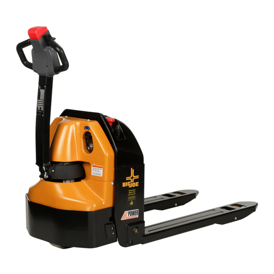
D40
SELF-PROPELLED,
PALLET LIFT TRUCK
U.S. Patents Nos. D739,112; D770,719; D770,720; 9,586,605
Operation
Maintenance
Repair Parts List
NOTE: For the most current parts information and service updates, please refer to the Big Joe
Support site at
www.bigjoesupport.com
Big Lift LLC
MANUAL NO. BL-D40-0515 - 01-27-2019
www.bigjoeforklifts.com
Advertisement
Table of Contents

Subscribe to Our Youtube Channel
Related Manuals for Big Lift D40


Summary of Contents for Big Lift D40
- Page 1 U.S. Patents Nos. D739,112; D770,719; D770,720; 9,586,605 Operation Maintenance Repair Parts List NOTE: For the most current parts information and service updates, please refer to the Big Joe Support site at www.bigjoesupport.com Big Lift LLC MANUAL NO. BL-D40-0515 - 01-27-2019 www.bigjoeforklifts.com...
- Page 2 WARNING Do not operate this truck unless you have been autho- care when traveling without load as the risk of overturn rized and trained to do so, and have read all warnings may be greater. and instructions in Operator’s Manual and on this Always look in direction of travel.
-
Page 3: Table Of Contents
SPEED POTENT. REPLACEMENT....5-3 10-1.8. EMERG. DISCONNECT INSTALLATION.. 10-2 5-1.6. BELLY-BUTTON SWITCH REPLACE..5-3 10-1.9. CONTACTOR REMOVAL......10-2 5-1.7. HORN SWITCH REPLACEMENT....5-4 10-1.10. CONTACTOR INSTALLATION....10-2 5-1.8. LIFT / LOWER SWITCH REPLACEMENT ...5-5 10-1.11. FUSE REMOVAL........10-2 BL-D40-0515 - 01-27-2019... - Page 4 LIST OF ILLUSTRATIONS Figure Page Figure Page NAME PLATE ............. 1-1 PUMP & MOTOR ASSY........9-3 D40 LIFT TRUCK..........1-1 LIFT CYLINDER ........... 9-5 SAMPLE OF OPERATOR CHECK LIST ..... 2-3 10-1 ELECTRICAL COMPONENTS (SHEET 1) ..10-3 FORWARD/REVERSE CONTROL...... 2-4 10-2 ELECTRICAL COMPONENTS (SHEET 2) ..
-
Page 5: Description1-1
The lift truck must be pro- tected from the elements. This publication describes the 24 volt D40 lift truck dis- tributed by Big Lift LLC. Included are operating instruc- The model number will be found on the name plate... -
Page 6: Safety Features
1-3. SAFETY FEATURES. • Readily accessible horn button. The D40 is designed and engineered to provide maxi- • Handle to provide a firm hand hold for operator. mum safety for operator and payload. Some of the • Flow control valve regulates maximum lowering safety features incorporated into the design are: speed within prescribed limits. -
Page 7: General
This section gives detailed operating instructions for load or lifting mechanism trailing. the D40 lift truck. The instructions are divided into the various phases of operations, such as operating lift, • Do not overload truck. Check nameplate for load driving, and stopping. - Page 8 Check that battery can be control head operate in all disconnect disconnected and recon- speed ranges in forward and nected. Check for connector reverse and that belly button damage. switch functions. Battery charge Check the battery indicator. BL-D40-0515 - 01-27-2019...
-
Page 9: Sample Of Operator Check List
R6479 Figure 2-1 Sample of Operator Check List BL-D40-0515 - 01-27-2019... -
Page 10: General Control Operation
Deadman braking occurs is being driven toward the operator, the switch when the handle is released and spring action raises changes the direction of the lift truck. steering arm to the upright position. BL-D40-0515 - 01-27-2019... -
Page 11: Steering Arm Gas Spring
Turn off the emergency 2-8. LIFT AND LOWER CONTROLS. Disconnect and the key switch. Charge batteries as necessary. Refer to battery care instructions, SEC- Lift/Lower Control buttons are located on the steering TION 3. control head. (Figure 2-3) BL-D40-0515 - 01-27-2019... - Page 12 NOTES BL-D40-0515 - 01-27-2019...
-
Page 13: Planned Maintenance3-1
Leakage voltage from battery terminals to battery case accordingly. These procedures must be performed by can cause misleading trouble symptoms with the truck a qualified service technician or your Big Lift LLC Ser- electrical system. Since components of the truck elec- vice Representative. -
Page 14: Safety Rules
Gas formed during charging amount of gasses be released from the battery. Also, is highly explosive and can cause seri- being a valve regulated battery, it never requires ous injury. watering. BL-D40-0515 - 01-27-2019... -
Page 15: Charging Batteries
NOT attempt to charge the batteries. Contact appropriate personnel for repairs to be made. Pull the charger cord (1, Figure 3-1) out of the top cover and connect to the appropriate power sup- ply. D40-24 Figure 3-1 Charging Battery BL-D40-0515 - 01-27-2019... -
Page 16: Batteries Replacement
3-2) and remove cover (2). D40-26 Figure 3-3 Controller Board Removal D40-25 Install in the reverse order of remove. Pay Figure 3-2 Cover Removal attention to battery position and cable con- nection. Position cables to avoid damage. BL-D40-0515 - 01-27-2019... -
Page 17: Lubrication
Hydraulic oil-Heavy duty with a viscosity of 100 SUS foam suppressing agent and rust and oxidation inhibitors (Note) No. 4 SAE 30 or 40 Engine lubricating oil NOTE: USED ON COLD CONDITIONED TRUCKS BL-D40-0515 - 01-27-2019... -
Page 18: Lubrication Diagram
Hydraulic Reservoir No. 3 With lift carriage fully lowered, fill Capacity-1 quarts reservoir with hydraulic oil to 1 inch below opening Lift Linkage Fittings* No. 2 Pressure lubricate. * Raise lift carriage to gain access to grease fittings. BL-D40-0515 - 01-27-2019... -
Page 19: General
Defective electric brake (2, Fig- Replace brake. 12-5). Brake will not release. a. Brake temperature above Allow to cool. 281F (140 C). b. Open brake circuitry or wiring. Make voltage checks. BL-D40-0515 - 01-27-2019... - Page 20 Forks do not lift, motor runs. Defect in hydraulic system. Check the oil level in the reservoir and the oil lines to the lift cylin- der, and repair as required. If normal, check the hydraulic pump, and relief valve. Repair, or adjust. BL-D40-0515 - 01-27-2019...
- Page 21 Check wiring and repair as required. Steering arm jerks excessively Drive wheel worn. Replace drive wheel if worn to starting or stopping the truck. within 3/4 inch of hub. Drive motor is jerky. Motor internally damaged or worn. Replace motor. BL-D40-0515 - 01-27-2019...
-
Page 22: Controller Troubleshooting
The Zapi Handset is available through your Big Lift LLC dealer. This function permits a deeper diagnosis of problems If you require dealer location information, contact Big as the recent history can be revisited. -
Page 23: 4-2.4. Settings And Adjustments
This input must be connected to a Keyswitch controlled voltage. The SR#1 becomes active when CNA#15 (Table 4-5) is open. The inching backward becomes active when the CNA#15 (Table 4- 5) is closed to a Keyswitch controlled voltage. BL-D40-0515 - 01-27-2019... - Page 24 ON/OFF: If this options is programmed ON the traction Inverter manages a hydraulic steering function when the keyswitch is switched ON (only if the AUX OUTPUT #1 option is programmed as HYDRO CONTACT or as WXCLUSIVE HYDRO). STOP ON RAMP Not used. BL-D40-0515 - 01-27-2019...
- Page 25 • NONE: The quick inversion function is not managed (no effect when CNB#7 (Table 4-5) switches over). • TIMED: The quick inversion function is timed. • BELLY: The quick inversion function is managed but not timed. Table 4-2 Set Options - Continued BL-D40-0515 - 01-27-2019...
- Page 26 Bus: the handling of the Hydraulics is specified on the TRUCK TYPE setting. • ABSENT: The MDI-PRC is not connected to the ACO: the TRUCK TYPE disappears from the SET OPTIONS function list. MOT SET-UP LOCK Not used. BL-D40-0515 - 01-27-2019...
-
Page 27: Zapi Handset
Selects the nominal battery voltage. ADJUST BATTERY XX V Do not modify - Factory adjusted (Fine adjustment of the battery voltage measured by the controller.) THROTTLE 0 ZONE Establishes a deadband in the accelerator input curve. Table 4-3 Adjustments - Continued BL-D40-0515 - 01-27-2019... -
Page 28: Throttle Regulation
• OPTION#1: CHECK UP NEEDED warning on the handset and MDIPRC after 300 hours. • OPTION#2: Equal to OPTION#1 but Speed reduction after 340 hours. • OPTION#3: Equal to OPTION#2 but the truck definitively stops after 380 hours. R6642 Figure 4-4 Throttle Regulation 4-10 BL-D40-0515 - 01-27-2019... -
Page 29: Zapi Handset
100 Hz Typically from 90 Hz to 160 Hz. It determines the maximum speed in forward direction. MAX SPEED BACK 100 Hz Typically from 90 Hz to 160 Hz. It determines the maximum speed in backward direction. BL-D40-0515 - 01-27-2019 4-11... - Page 30 It is used to push up, in feedforward way, the torque when it is not possible to control the flux, in feedback way, because of the low frequency. 4-12 BL-D40-0515 - 01-27-2019...
-
Page 31: Zapi Controller
Encoder Negative Supply (GND to minus battery) CNA#11 HM(+B) Output for driving an hourmeter; when the hourmeter is active this output provides a +Batt signal; 3 maximum current. Table 4-5 Zapi Controller Connector Pins - Continued BL-D40-0515 - 01-27-2019 4-13... - Page 32 Lifting request input, active high. CNB#10 CPOT Lifting request input, active high. CNB#11 NPOT Negative of accelerator unit, tested for wire disconnection diagnosis. CNB#12 PPOT Potentiometer positive: 10V output; keep load >1k Table 4-5 Zapi Controller Connector Pins - Continued 4-14 BL-D40-0515 - 01-27-2019...
- Page 33 Negative console power supply. CNC#6 +12V Positive console power supply. CNC#7 FLASH Must be connected to C8 for the Flash memory programming (if used). CNC#8 FLASH Must be connected to C7 for the Flash memory programming (If used). BL-D40-0515 - 01-27-2019 4-15...
- Page 34 NOTES 4-16 BL-D40-0515 - 01-27-2019...
-
Page 35: Steering Arm, Control Head And Compart
STEERING ARM, CONTROL HEAD AND COMPARTMENT 5-1. CONTROL HEAD Remove the cap assembly as described in para- graph 5-1.3. 5-1.1. Control Head Removal Disconnect wire harness assembly from potenti- Turn off key switch and emergency disconnect. ometer. DK_0001 Figure 5-1 Steering Arm BL-D40-0515 - 01-27-2019... - Page 36 Remove the remaining two screws, two washers arm. and two flat washers that holds control head to the steering arm. Remove the control head and handle. DK_0002 Figure 5-2 Control Head BL-D40-0515 - 01-27-2019...
-
Page 37: 5-1.2. Control Head Installation
Remove screw, washer and control knob from other and flat washers. side of potentiometer. Reconnect wire harness assembly to emergency reverse switch. 10. Install the cap assembly as described in para- graph 5-1.4. BL-D40-0515 - 01-27-2019... -
Page 38: 5-1.7. Horn Switch Replacement
5-1.3. secure with three screws. Remove three screws, switch bracket and two Install the cap assembly as described in para- springs of assembly. graph 5-1.4. Remove the two pins of assembly and remove switch from the bracket. BL-D40-0515 - 01-27-2019... -
Page 39: 5-1.8. Lift / Lower Switch Replacement
Remove switch assembly from the cap. Position switch assembly in cover and secure with Remove pin securing buttons to the bracket and pin. remove the buttons. Install the cap assembly as described in para- graph 5-1.4. BL-D40-0515 - 01-27-2019... -
Page 40: Compartment Covers
Figure 5-5 Compartment Cover Feed the cable through cover and position cover Install cap on cable and position the cap on cover. on the frame. Secure with two screws and two Turn on key switch and emergency disconnect. washers. BL-D40-0515 - 01-27-2019... -
Page 41: Steering Arm
Reconnect wire harness assembly to harness. ing arm being sure it fully engages its seat. Install steering arm gas return spring as described Position the opposite end of gas return spring on in paragraph 5-3.1. bracket and install screw. BL-D40-0515 - 01-27-2019... - Page 42 BL-D40-0515 - 01-27-2019...
-
Page 43: Brake Servicing6-1
Turn the three mounting screws clockwise until the gap measures 0.012” (0.25 mm). The threaded air gap adjusting nuts are then R6625 screwed clockwise until they bottom. Finally tighten the three mounting screws to Figure 6-1 Brake Assembly 52 in-lb (6 Nm). BL-D40-0515 - 01-27-2019... -
Page 44: Stopping Distance Adjustment
Reconnect electric brake from harness. Rotate the adjusting nut (Figure 6-1) clockwise to Remove load wheel blocks and check operation. SHORTEN the stopping distance or counterclock- Install the compartment covers as described in wise to LENGTHEN the stopping distance. paragraph 5-2. BL-D40-0515 - 01-27-2019... -
Page 45: Load Wheel
NOTE: Inspect the load wheel assembly. If the load wheel is worn within 1/8" of the metal sleeve, or is cracked or damaged, replace the entire load wheel and bearing assembly. Big Lift LLC recommends that both load wheel assemblies be replaced at the same time. -
Page 46: Drive Wheel
Slowly lower the transmission out the bottom of paragraph 5-2. the frame. Turn on key switch and emergency disconnect. 10. Install new transmission by reversing the steps above. 7-3. Transmission. Turn off key switch and emergency disconnect. BL-D40-0515 - 01-27-2019... -
Page 47: Transmission Motor, Brake Mounting
DK_0006 Figure 7-2 Transmission Motor, Brake Mounting BL-D40-0515 - 01-27-2019... - Page 48 BL-D40-0515 - 01-27-2019...
-
Page 49: Elevation System Servicing8-1
8-2.1. Removal Lower link assembly to the floor. Lift complete truck to height sufficient to permit access to lift linkage under forks. Provide blocking Remove pins and remove shafts. Lower links to the floor. DK_0010 Figure 8-1 Frame BL-D40-0515 - 01-27-2019... -
Page 50: Repair
Loosen nuts and remove clevises from tension bars. Remove blocking and lower the truck to the ground. Turn on key switch and emergency disconnect. DK_0011 Figure 8-2 Lift Linkage Assembly BL-D40-0515 - 01-27-2019... -
Page 51: Hydraulic System Servicing9-1
Lower forks fully. maintenance on the hydraulic system. Turn off key switch and emergency disconnect. Remove the compartment covers as described in paragraph 5-2. DK_0014 Figure 9-1 Hydraulic System BL-D40-0515 - 01-27-2019... -
Page 52: Removal
Tag and disconnect all harnesses and cables from Refer to Figure 9-2 for disassembly and reassem- electrical components on board. bly. Support board and remove four screws , four lock washers and four flat washers. Remove board. BL-D40-0515 - 01-27-2019... - Page 53 DK_0015 Figure 9-2 Pump & Motor Assy BL-D40-0515 - 01-27-2019...
-
Page 54: Installation
1 inch below opening. If required, add hydraulic relieve pressure on the cylinder. oil to bring to proper level. Use hydraulic oil listed Remove retaining rings and pin. Table 3-2. Remove cylinder. Install the compartment cover as described in paragraph 5-2. BL-D40-0515 - 01-27-2019... - Page 55 DK_0016 Figure 9-3 Lift Cylinder BL-D40-0515 - 01-27-2019...
- Page 56 NOTES BL-D40-0515 - 01-27-2019...
-
Page 57: Electrical Components
Reconnect master wire harness to charger. tight. Use two well insulated wrenches for this Install compartment covers as described in para- task in order to avoid steering the buss bars. graph 5-2. 10-1.3.Controller Removal. Turn on key switch and emergency disconnect. BL-D40-0515 - 01-27-2019 10-1... -
Page 58: 10-1.9.Contactor Removal
Install fuse on the stand and secure two nuts. Install compartment covers as described in para- 10-1.9.Contactor Removal. graph 5-2. Turn off key switch and emergency disconnect. Turn on key switch and emergency disconnect. Remove the compartment covers as described in paragraph 5-2. 10-2 BL-D40-0515 - 01-27-2019... - Page 59 DK_0019 Figure 10-1 Electrical Components (Sheet 1) BL-D40-0515 - 01-27-2019 10-3...
-
Page 60: 10-1.13.Cooling Fan Removal
Reconnect switch wiring harness to battery indi- cator. Install compartment covers as described in para- graph 5-2. Install compartment covers as described in para- graph 5-2. Turn on key switch and emergency disconnect. Turn on key switch and emergency disconnect. 10-4 BL-D40-0515 - 01-27-2019... - Page 61 DK_0020 Figure 10-2 Electrical Components (Sheet 2) BL-D40-0515 - 01-27-2019 10-5...
-
Page 62: 10-1.21.Lift Limit Switch Removal
Install compartment covers as described in para- graph 5-2. Tag and disconnect master wire harness from limit switch. Turn on key switch and emergency disconnect. Remove two nuts, screws, lock washers and limit switch from bracket. DK_0017 Figure 10-3 Electric System 10-6 BL-D40-0515 - 01-27-2019... -
Page 63: 10-4.1.Replacement
The drive motor is replaceable but not repairable. Position bracket on bracket and secure with two Refer to paragraph 7-3. screws and lock washers. 10-4.DEADMAN SWITCH Install compartment covers as described in para- graph 5-2. 10-4.1.Replacement Turn on key switch and emergency disconnect. BL-D40-0515 - 01-27-2019 10-7... - Page 64 NOTES 10-8 BL-D40-0515 - 01-27-2019...
-
Page 65: Optional Equipment
SECTION 11 OPTIONAL EQUIPMENT BL-D40-0515 - 01-27-2019 11-1... - Page 66 NOTES 11-2 BL-D40-0515 - 01-27-2019...
-
Page 67: Illustrated Parts Breakdown
SECTION 12 ILLUSTRATED PARTS BREAKDOWN Following is an illustrated parts breakdown of assemblies and parts associated with the D40 Lift Truck. BL-D40-0515 - 01-27-2019 12-1... - Page 68 DK_0001 Figure 12-1 Steering Arm 12-2 BL-D40-0515 - 01-27-2019...
-
Page 69: Steering Arm
SCREW, M4 X 12 0000-000122-00 LOCK WASHER, M4 0000-000377-00 SCREW, M2 X 20 0000-000378-00 SCREW, M4 X 16 0000-000702-00 FLAT WASHER, M4 0000-000491-00 HARNESS CLAMP 0000-000139-00 NUT, M4 0000-000109-00 SCREW, M8 X 16 1220-560001-00 INCHING SWITCH BL-D40-0515 - 01-27-2019 12-3... - Page 70 DK_0029 Figure 12-2 Steering Arm - Freezer 12-4 BL-D40-0515 - 01-27-2019...
- Page 71 1120-520005-LK HEATER BAND 0000-000378-00 SCREW M4×16 0000-000702-00 FLAT WASHER Ø4 0000-000491-00 HARNESS CLAMP 0000-000139-00 NUT M4 0000-000109-00 SCREW M8×16 2333-320000-10 CONTROL POD BRACKET 0000-000321-00 SCREW M8×20 0000-000176-00 FLAT WASHER Ø8 0000-000322-00 SCREW M8×25 0000-001329-10 SCREW M3×16 BL-D40-0515 - 01-27-2019 12-5...
- Page 72 DK_0002 Figure 12-3 Control Head - Used up to Serial Number 327120792 12-6 BL-D40-0515 - 01-27-2019...
-
Page 73: Control Head
0000-000322-00 SCREW M8×25 0000-000159-00 LOCK WASHER Ø8 0000-000176-00 FLAT WASHER Ø8 1120-340003-00 CONTROL KNOB (L) 1120-343000-00-B REVERSING SWITCH ASSEMBLY 0000-000004-00 SCREW M5×12 0000-000035-00 SCREW M5×20 1120-340002-00 COVER 1120-341000-00 GRIPE 1120-340001-00 1220-520008-0C ACCELERATOR ASSEMBLY 0000-000010-00 SCREW M5×6 BL-D40-0515 - 01-27-2019 12-7... - Page 74 DK_0033 Figure 12-4 Control Head - Used from Serial Number 327120793 12-8 BL-D40-0515 - 01-27-2019...
- Page 75 SCREW M5×16 0000-000390-00 FLATWASHER Ø5 1115-340007-00 WIRE HARNESS COVER 1120-520009-00 REVERSING SWITCH WIRE 0000-000989-00 SCREW M2×12 1115-340003-00 COVER 1121-310004-00 SPRING 1115-340002-00 COVER 0000-000322-00 SCREW M8×25 0000-000159-00 LOCKWASHER Ø8 0000-000176-00 FLATWASHER Ø8 1115-340001-00 WASHER 0000-000035-00 SCREW M5×20 BL-D40-0515 - 01-27-2019 12-9...
- Page 76 DK_0003 Figure 12-5 Cap Assembly 12-10 BL-D40-0515 - 01-27-2019...
-
Page 77: Cap Assembly
0000-000039-00 SCREW ST3.5×9.5 0000-000490-00 HARNESS CLAMP 1120-342200-00 LIFT AND LOWER BOX (R) ASSEMBLY 1120-342100-00 LIFT AND LOWER BOX (L) ASSEMBLY 1220-520006-0C BUTTONS ASSEMBLY 1220-560002-00 INCHING SWITCH II 1120-342002-00 HORN BUTTON 1120-342005-00 1120-342003-00 SPRING 1120-342004-00 BUTTON BRACKET BL-D40-0515 - 01-27-2019 12-11... - Page 78 DK_0027 Figure 12-5 Control Head - Freezer 12-12 BL-D40-0515 - 01-27-2019...
- Page 79 2333-340009-00 MOUNTING SEAT 2333-340012-00 SCREW ST2.9×9.5 2333-340010-00 SPRING 0000-000037-00 SCREW M3×12 0000-000038-00 LOCK WASHER Ø3 2333-340018-00 BRACKET 2333-340019-00 SCREW M3×10 2333-340020-00 COVER 2333-340022-00 COVER 2333-340023-00 BUTTON 2333-340024-00 SCREW M5×12 2333-340025-00 SCREW ST2.9×20 2333-340026-00 BUSHING 2333-340027-00 BUSHING BL-D40-0515 - 01-27-2019 12-13...
- Page 80 DK_0005 Figure 12-6 Emergency Reverse Switch Assembly - Used up to Serial Number 327120792 12-14 BL-D40-0515 - 01-27-2019...
- Page 81 EMERGENCY REVERSE SWITCH ASSEMBLY - Used up to Serial Number 327120792 Qty. Pos. Part Number Description Notes Reqd. 1120-343002-00 EMERGENCY REVERSE BUTTON 1120-343003-00 SPRING 1120-342005-00 1120-343001-0A BRACKET 1120-343004-00 1220-520005-0C WIRE HARNESS-REVERSING SWITCH 1220-560002-00 SWITCH BL-D40-0515 - 01-27-2019 12-15...
- Page 82 DK_0006 Figure 12-7 Transmission Motor, Brake Mounting 12-16 BL-D40-0515 - 01-27-2019...
-
Page 83: Transmission Motor, Brake Mounting
Non Marking Rubber Dia- 506161-11 DRIVE WHEEL ASSEMBLY mond-X Cut 1120-200001-20 DRIVE WHEEL ASSEMBLY Poly Diamond-X Cut 0000-000025-00 LOCK WASHER, M12 0000-000157-00 NUT, M12 X 1.25 0000-000070-00 SCREW, M10 X 25 1120-210002-00 BRAKE PLATE 1120-240014-30 STUDS BL-D40-0515 - 01-27-2019 12-17... - Page 84 DK_0007 Figure 12-8 Transmission Transmission Used up to Serial # E2219364 12-18 BL-D40-0515 - 01-27-2019...
- Page 85 FLAT WASHER, M14 0000-001055-00 WASHER, M14 0000-001056-00 NUT, M14 X 1.5 0000-000211-00 O-RING, 150 X 3.1 1120-240010-30 COVER 1120-240011-30 VENT PLUG 0000-000055-00 SCREW M6 X16 1120-240017-30 SEAL WASHER, TC80 X 65 X 8 1120-240013-30 OUTPUT SHAFT BL-D40-0515 - 01-27-2019 12-19...
- Page 86 DK_0024 Figure 12-9 Transmission Used between Serial # E2219365 - 327120197 12-20 BL-D40-0515 - 01-27-2019...
- Page 87 0000-001054-00 BEARING 1120-GB30-00 GEAR KIT Includes 2 gears 0000-000379-00 FLAT WASHER Ø14 0000-001055-00 WASHER Ø14 0000-001056-00 NUT M14×1.5 0000-000211-00 O-RING 150×3.1 1120-240010-30 COVER 1120-240011-30 GAS PLUG 0000-000055-00 SCREW M6×16 1120-240017-30 SEAL WASHER TC80×65×8 1120-240013-30 OUTPUT SHAFT BL-D40-0515 - 01-27-2019 12-21...
- Page 88 DK_0034 Figure 12-10 Transmission Used from serial number 327120198 12-22 BL-D40-0515 - 01-27-2019...
- Page 89 3030-110000-06 NUT M36 0000-001054-00 BEARING ZK12-GB30-00 GEAR Includes 2 gears 0000-000379-00 FLATWASHER Ø14 ZK12-240020-00 WASHER Ø14 3030-070000-04 NUT M14 0000-000211-00 O-RING 150×3.1 ZK12-240005-00 COVER ZK12-240019-00 PLUG 0000-000055-00 SCREW M6×16 3060-030000-17 SEAL WASHER TC80×65×8 ZK12-240007-00 OUTPUT SHAFT BL-D40-0515 - 01-27-2019 12-23...
- Page 90 DK_0008 Figure 12-11 Compartment Covers - Used up to serial number 324180206 12-24 BL-D40-0515 - 01-27-2019...
-
Page 91: Compartment Cover
1118-100002-00 UPPER COVER Big Joe Yellow 1118-100003-00 LOWER COVER Big Joe Yellow 0000-000649-00 SCREW, M8 X 20 2214-150002-00 WASHER 1118-100005-00 CHARGER CAP 0000-000126-00 SCREW, M6 X 16 0000-000119-00 SCREW, M5 X 12 1118-100004-00-01 MIDDLE COVER Black BL-D40-0515 - 01-27-2019 12-25... - Page 92 DK_0028 Figure 12-12 Compartment Covers - Used from serial number 324180207 12-26 BL-D40-0515 - 01-27-2019...
- Page 93 Used from serial number 1118-100003-1A LOWER COVER 324190036 - Big Joe Yellow 0000-000649-00 SCREW, M8 X 20 2214-150002-00 WASHER 1118-100005-00 CHARGER CAP 0000-000126-00 SCREW, M6 X 16 0000-000119-00 SCREW, M5 X 12 1118-100004-00-01 MIDDLE COVER Black BL-D40-0515 - 01-27-2019 12-27...
-
Page 94: Load Backrest
DK_0009 Figure 12-13 Load Backrest 12-28 BL-D40-0515 - 01-27-2019... - Page 95 1118-682000-00 BASKET Basket Only 1115-681000-K0 BRACKET 0000-000740-00 0000-000321-00 SCREW 0000-000159-00 LOCK WASHER Ø8 0000-000700-00 SCREW M8 X 16 0000-000030-00 SCREW 901803 LOAD RESTRAINT KIT Includes Items 11,12,13, 14, 15 Included in Item 12 0000-000070-00 SCREW 0000-000054-00 BL-D40-0515 - 01-27-2019 12-29...
- Page 96 DK_0010 Figure 12-14 Frame 12-30 BL-D40-0515 - 01-27-2019...
- Page 97 Used between E2410520- 1118-110000-4A-02 FORK FRAME 324180206 . Fork Length 48”, Fork Width 27” Used from 324180207.. Fork 1118-110000-E0-02 FORK FRAME Length 48”, Fork Width 27” 1118-130003-00 LINK 1115-130004-0A SHAFT 0000-000708-00 ROUND PIN Ø5×35 0000-000056-00 LOCK WASHER Ø6 BL-D40-0515 - 01-27-2019 12-31...
-
Page 98: Frame
DK_0010 Figure 12-15 Frame continued 12-32 BL-D40-0515 - 01-27-2019... - Page 99 LOCK WASHER Ø8 0000-000176-00 FLAT WASHER Ø8 0000-000109-00 SCREW M8×16 0000-000055-00 SCREW M6×16 0000-001130-00 BUSHING 1612 Used from 07-04-2013- 1118-101000-10 PLATE 0000-000008-00 SCREW M10×20 Used between serial numbers E2316808-E2410519 0000-000063-00 LOCK WASHER Ø10 0000-000007-00 FLAT WASHER Ø10 BL-D40-0515 - 01-27-2019 12-33...
- Page 100 DK_0011 Figure 12-16 Lift Link Assembly 12-34 BL-D40-0515 - 01-27-2019...
-
Page 101: Lift Link Assembly
1115-130003-00 LOAD WHEEL BRACKET PIVOT SHAFT 0000-000708-00 PIN, M5 X 35 1115-130007-40 LOAD WHEEL SHAFT 1115-133000-40 LOAD WHEEL 0000-000435-00 FLAT WASHER, M20 1118-132100-70 LONG ROD Fork length 36” 1118-132100-20 LONG ROD Fork length 48” 1115-130008-00 WASHER BL-D40-0515 - 01-27-2019 12-35... - Page 102 DK_0012 Figure 12-17 Load Wheel 12-36 BL-D40-0515 - 01-27-2019...
-
Page 103: Load Wheel
LOAD WHEEL Qty. Pos. Part Number Description Notes Reqd. — 1115-133000-40 LOAD WHEEL ASSEMBLY Including bearings 0000-000020-00 BEARING 1115-133002-40 LOAD WHEEL BL-D40-0515 - 01-27-2019 12-37... - Page 104 DK_0013 Figure 12-18 Caster 12-38 BL-D40-0515 - 01-27-2019...
-
Page 105: Caster
NUT, M12 Used up to 02-25-2014 0000-000057-00 NUT, M12 Used from 02-26-2014 0000-000063-00 LOCK WASHER, M10 0000-000007-00 FLAT WASHER, M10 0000-000435-00 FLAT WASHER M20 0000-000060-00 LOCK WASHER, M12 0000-000373-00 FLAT WASHER, M12 0000-000004-00 SCREW, M5 X 12 BL-D40-0515 - 01-27-2019 12-39... -
Page 106: Hydraulic System
DK_0014 Figure 12-19 Hydraulic System 12-40 BL-D40-0515 - 01-27-2019... - Page 107 1118-430000-0A HOSE ASSY E2410520 1118-420000-00 PUMP & MOTOR ASSY 0000-000321-00 SCREW, M8 X 20 0000-000159-00 LOCK WASHER, M8 0000-000176-00 FLAT WASHER, M8 1118-410000-00 CYLINDER 0000-000293-00 RETAINING RING, M20 1118-400001-00 SHAFT 0000-000210-00 FLAT WASHER, M8 0000-000705-00 BUSHING BL-D40-0515 - 01-27-2019 12-41...
-
Page 108: Pump & Motor Assy
DK_0015 Figure 12-20 Pump & Motor Assy 12-42 BL-D40-0515 - 01-27-2019... - Page 109 1115-560011-00 GEAR PUMP 1115-560012-00 WASHER, M5 1115-560013-00 SCREW, M5 X 70 1115-560015-00 OIL FILTER 1118-420020-00 SUCTION PIPE 1118-420021-00 O-RING, 69 X 3.5 1118-420022-00 OIL TANK 1120-430023-00 O-RING, 11.2 X 2.65 1115-560024-00 AIR FILTER 1115-561001-00 CARBON BRUSH BL-D40-0515 - 01-27-2019 12-43...
- Page 110 DK_0016 12-44 BL-D40-0515 - 01-27-2019...
-
Page 111: Lift Cylinder
SEAL KIT Includes Items 2, 3, 7 1118-410001-00 PISTON ROD 0000-000672-00 WIPER RING, M40 X 50 X 5-6.5 0000-000673-00 O-RING, M45 X 3.1 1115-410002-0B GLAND NUT 1118-411000-00 CYLINDER BODY 1115-410003-0B GUIDE RING 0000-000512-00 VX-SEAL 1115-410004-00 BUSHING BL-D40-0515 - 01-27-2019 12-45... - Page 112 DK_0017 Figure 12-22 Electrical System 12-46 BL-D40-0515 - 01-27-2019...
-
Page 113: Electrical System
BATTERY 100Ah Battery 1118-100011-00 SPACER A.R. As required 1118-100010-00 PLATE Used up to 04/23/2014 0000-000055-00 SCREW, M6 X 16 Used up to 04/23/2014 1115-100002-00 SPACER A.R. As required 1280-100005-00 FLAT PLUG Up to Serial # 324170264 BL-D40-0515 - 01-27-2019 12-47... - Page 114 DK_0018 Figure 12-23 Drive Motor Assembly 12-48 BL-D40-0515 - 01-27-2019...
-
Page 115: Motor Assembly
TERMINAL BLOCK 0000-000206-00 LOCK WASHER, M5 0000-000117-00 SCREW, M5 X 10 0000-000166-00 NUT, M6 0000-000056-00 LOCK WASHER, M6 1120-220002-00 BEARING 0000-000204-00 0000-000409-00 O-RING, M63 X 3.55 0000-000436-00 NUT, M12 X 1.5 0000-000323-00 SCREW, M5 X 16 BL-D40-0515 - 01-27-2019 12-49... -
Page 116: Electrical Components (Sheet 1)
DK_0019 Figure 12-24 Electrical Components (Sheet 1) 12-50 BL-D40-0515 - 01-27-2019... - Page 117 1120-540001-00-B FUSE STAND 1120-540002-00 FUSE, 200A 0000-000074-00 SCREW, M6 X 20 0000-000550-00 NUT, M8 0000-000210-00 FLAT WASHER, M8 0000-000004-00 SCREW, M5 X 12 0000-000206-00 LOCK WASHER, M5 1120-500004-00-30 CONTROLLER AC0 1120-500005-10 CONTACTOR 1118-560006-00-01 CHARGER ASSEMBLY 15A BL-D40-0515 - 01-27-2019 12-51...
- Page 118 DK_0019 Figure 12-24Electrical Components (Sheet 1) - Continued 12-52 BL-D40-0515 - 01-27-2019...
- Page 119 1118-510005-10 PLATE II E2316808 to E2410289 Only used from Serial # 0000-000035-00 SCREW M5×20 E2316808 to E2410289 Used from Serial # 0000-000004-00 SCREW M5×12 E2410290 Used from Serial # 1220-150005-00 NUT M8 E2316808 1115-510008-10 SWITCH BUTTON BL-D40-0515 - 01-27-2019 12-53...
- Page 120 DK_0020 Figure 12-25 Electrical Components (Sheet 2) 12-54 BL-D40-0515 - 01-27-2019...
- Page 121 0000-000139-00 NUT, M4 1115-520007-00 FAN ASSEMBLY 1115-500007-00 FAN GUARD 0000-000121-00 SCREW, M4 X 35 0000-000122-00 LOCK WASHER, M4 0000-000702-00 FLAT WASHER, M4 1115-520019-0A 2-WAY SWITCH 1115-500016-00 2-WAY SWITCH KEY 1115-520013-00 LED WIRE HARNESS 1115-510009-00 LAMP HOLDER BL-D40-0515 - 01-27-2019 12-55...
- Page 122 DK_0020 Figure 12-25 Electrical Components (Sheet 2) - Continued 12-56 BL-D40-0515 - 01-27-2019...
-
Page 123: Electrical Components (Sheet 2)
BDI dial to the following: M 1115-510006-20 BDI (BATTERY INDICATOR) = Industrial Battery, Q = Maint.Free Battery Only used from Serial # 1118-510004-10 PLATE I E2316808 to E2410289 Used from serial number 0000-000108-00 NUT M6 324170265 BL-D40-0515 - 01-27-2019 12-57... - Page 124 DK_0030 Figure 12-25 Electrical Components - Freezer 12-58 BL-D40-0515 - 01-27-2019...
- Page 125 ELECTRICAL COMPONENTS - FREEZER Qty. Part Number Description Notes Reqd. 1220-520014-X0 HEATER BAND,VALVE 1120-520004-X0 HEATER BAND,BRAKE 1221-500002-X0 CLAMP 2108-520003-LK TEMPERATURE DETECT SWITCH 0000-000009-00 SCREW M4×12 0000-000122-00 LOCK WASHER Ø4 0000-000702-00 FLAT WASHER Ø4 BL-D40-0515 - 01-27-2019 12-59...
- Page 126 DK_0021 Figure 12-26 Wiring Harness 12-60 BL-D40-0515 - 01-27-2019...
-
Page 127: Wiring Harness
Qty. Pos. Part Number Description Notes Reqd. 1118-520001-00 MASTER WIRE HARNESS 1120-500010-00 FUSE 10A 1118-520002-00 SWITCHING WIRE HARNESS 1118-520004-00 WIRE HARNESS OF PUMP Only used up to serial num- 1118-520008-10 SHORT CIRCUIT SWITCH ber 324170264 (Optional) BL-D40-0515 - 01-27-2019 12-61... - Page 128 DK_0031 Figure 12-27 Wiring Harness - Freezer 12-62 BL-D40-0515 - 01-27-2019...
- Page 129 WIRING HARNESS - FREEZER Qty. Pos. Part Number Description Notes Reqd. 1118-520001-X0 MASTER WIRE HARNESS 1120-500010-00 FUSE 10A 1118-520002-X0 SWITCHING WIRE HARNESS 1118-520004-X0 WIRE HARNESS OF PUMP BL-D40-0515 - 01-27-2019 12-63...
- Page 130 DK_0022 Figure 12-28 Wiring Cables 12-64 BL-D40-0515 - 01-27-2019...
-
Page 131: Wiring Cables
1118-531004-00 F CABLE + 1118-531006-00 M CABLE + 1118-531008-00 B CABLE+ 1118-531007-00 PUMP POWER CABLE + 1118-531005-00 PUMP POWER CABLE - 1118-532001-00 DRIVING MOTOR CABLE U 1118-532002-00 DRIVING MOTOR CABLE V 1118-532003-00 DRIVING MOTOR CABLE W BL-D40-0515 - 01-27-2019 12-65... - Page 132 Big Lift LLC...
Need help?
Do you have a question about the D40 and is the answer not in the manual?
Questions and answers