Sign In
Upload
Download
Table of Contents
Contents
Add to my manuals
Delete from my manuals
Share
URL of this page:
HTML Link:
Bookmark this page
Add
Manual will be automatically added to "My Manuals"
Print this page
×
Bookmark added
×
Added to my manuals
Manuals
Brands
LEGRAND Manuals
Medical Equipment
MOSAIC Series
Installation and user manual
LEGRAND MOSAIC Series Installation And User Manual
Nurse call unit
Hide thumbs
Also See for MOSAIC Series
:
Manual
(13 pages)
1
2
3
4
5
6
7
8
9
10
11
12
13
14
15
16
17
18
19
20
21
22
23
24
25
26
27
28
29
30
31
32
33
34
35
36
37
38
39
40
41
42
43
44
45
46
47
48
49
50
page
of
50
Go
/
50
Contents
Table of Contents
Troubleshooting
Bookmarks
Table of Contents
Mosaic
Table of Contents
Description of the System Architecture
Selection Guide: How to Draw up Your List of Equipment
766 60: 6-Direction Call Display Unit
Presentation and Installation of Devices
782 12: 3-Direction Management Module
782 14: Table Control Unit
782 89/0 035 67 or E49: Power Supplies
782 04: Door Unit
Management Module Cat
Cat. No. 0 800 41
766 85: Bathroom Call Units or Call Button
Door Unit Cat
Cat. No. 0 800 41
766 63: Socket for Corded Push-Button
Socket for Corded Push-Button Cat
782 41/46: Sockets for Hand-Held Remote Control Units
782 45/47: Sockets for Hand-Held Remote Control Units
782 01/02/03: Hand-Held Remote Control Units
782 43: Clamp for Corded Push-Button
Technical Characteristics
Operating Temperature: 5 to 40°C
Storage Temperature: -20 to 70°C
783 77/78/79: Remote Control Modules
766 64: Bathroom Call Pull-Cord (18W10)
804 12: Spare Part for Bathroom Call Pull-Cord
Protection Index: IP
766 72: Double Display Corridor Overdoor Light
766 42: Electronic Buzzer
In 1-Gang Flush-Mounting Box (2 Modules)
Surface-Mounted Wall Installation with Box Cat. No. 0 802 81
771 50 + 0 782 07: Biomedical Call Plug and Socket
Door Unit Cat
R - Red LED Indicator W - White LED Indicator
Cat. No. 0 802 51
Call + Nurse Present
Operating Mode
Bathroom Call + Nurse Present
Call for Nurse Assistance (Emergency)
Nurse Present + Call from Another Room
Nurse Present + Call from Another Bathroom
Call Priorities
Mosaic Nurse Call Unit Wiring
Call + Presence Installation for Nursing Homes and Residential Homes for the Elderly
Call + Presence Installation with Hand-Hand-Held Remote Control Units and Magnetic Sockets
Call + Presence Installation with Call Via Push-Button with Indicator and Information Transfer
Corridor Overdoor Light Unit
Corridor Overdoor Light Unit
Corridor Overdoor Light Unit
V Cable for Patient Call + Corridor Display Units and IP Network Cabling
Commissioning
Resetting the Module
Troubleshooting
Advertisement
Quick Links
1
Table of Contents
2
Selection Guide: How to Draw up Your List of Equipment
3
766 60: 6-Direction Call Display Unit
4
782 12: 3-Direction Management Module
5
782 04: Door Unit
6
766 85: Bathroom Call Units or Call Button
Download this manual
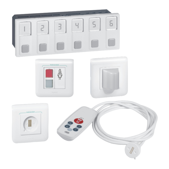
MOSAIC
NURSE CALL UNIT
INSTALLATION AND USER GUIDE
THE GLOBAL SPECIALIST IN ELECTRICAL
AND DIGITAL BUILDING INFRASTRUCTURES
Table of
Contents
Previous
Page
Next
Page
1
2
3
4
5
Advertisement
Chapters
Mosaic
2
Description of the System Architecture
10
782 45/47: Sockets For Hand-Held Remote Control Units
19
Table of Contents
Need help?
Do you have a question about the MOSAIC Series and is the answer not in the manual?
Ask a question
Questions and answers
Related Manuals for LEGRAND MOSAIC Series
Switch LEGRAND Mosaic Series Manual
Automatic switch (13 pages)
Switch LEGRAND Mosaic 0 766 60 Manual
Nurse call unit (7 pages)
Medical Equipment LEGRAND Aidcall Touchsafe Pro Installation Manual
Wireless nursecall system location pendant (10 pages)
Medical Equipment LEGRAND Tynetec AidCall Alarm Pullcord Manual
169mhz telecare devices (4 pages)
Medical Equipment LEGRAND tynetec Aidcall Quick Start Manual
169mhz telecare devices enuresis sensor & cotton bed sheet (6 pages)
This manual is also suitable for:
0 766 60
0 035 67
0 782 12
0 035 e49
0 782 04
0 766 85
...
Show all
0 766 63
0 783 62
0 782 41
0 782 46
0 782 45
0 782 47
0 782 01
078 14
0 782 02
0 782 03
0 782 43
0 783 77
0 782 89
0 783 78
0 783 79
0 766 64
0 766 72
0 766 71
0 766 42
0 771 50
0 782 07
Table of Contents
Print
Rename the bookmark
Delete bookmark?
Delete from my manuals?
Login
Sign In
OR
Sign in with Facebook
Sign in with Google
Upload manual
Upload from disk
Upload from URL


Need help?
Do you have a question about the MOSAIC Series and is the answer not in the manual?
Questions and answers