Table of Contents
Advertisement
Quick Links
ACDEU
OM-00698-08
August 22, 2005
Rev. B 11-03-09
INSTALLATION, OPERATION,
AND MAINTENANCE MANUAL
WITH PARTS LIST
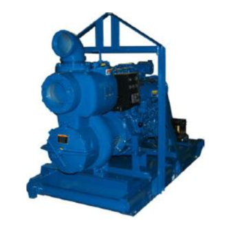
10 SERIES PUMP
MODEL
16A2−F3L
THE GORMAN-RUPP COMPANY D MANSFIELD, OHIO
D
GORMAN-RUPP OF CANADA LIMITED
ST. THOMAS, ONTARIO, CANADA
Printed in U.S.A.
www.grpumps.com
E
2005 The Gorman-Rupp Company
Advertisement
Table of Contents

Related Manuals for GORMAN-RUPP PUMPS 16A2-F3L


Summary of Contents for GORMAN-RUPP PUMPS 16A2-F3L
- Page 1 ACDEU OM-00698-08 August 22, 2005 Rev. B 11-03-09 INSTALLATION, OPERATION, AND MAINTENANCE MANUAL WITH PARTS LIST 10 SERIES PUMP MODEL 16A2−F3L THE GORMAN-RUPP COMPANY D MANSFIELD, OHIO GORMAN-RUPP OF CANADA LIMITED ST. THOMAS, ONTARIO, CANADA Printed in U.S.A. www.grpumps.com 2005 The Gorman-Rupp Company...
- Page 2 Register your new Gorman-Rupp pump online at www.grpumps.com Valid serial number and e-mail address required. The engine exhaust from this product contains chemicals known to the State of California to cause cancer, birth defects or other reproductive harm. RECORD YOUR PUMP MODEL AND SERIAL NUMBER Please record your pump model and serial number in the spaces provided below.
-
Page 3: Table Of Contents
TABLE OF CONTENTS INTRODUCTION ..........PAGE I −... - Page 4 TABLE OF CONTENTS (continued) Automatic Stopping ........... . PAGE C −...
-
Page 5: Introduction
10 SERIES OM−00698 INTRODUCTION Thank You for purchasing a Gorman-Rupp pump. neither operator safety nor pump integrity are com- Read this manual carefully to learn how to safely promised by the installation. Pumps and related install and operate your pump. Failure to do so equipment must be installed and operated ac- could result in personal injury or damage to the cording to all national, local and industry stan-... -
Page 6: Safety − Section A
10 SERIES OM−0698 SAFETY − SECTION A This information applies to 10 Series en- vent injury during automatic operation. Disconnect the positive battery cable gine driven pumps. Refer to the manual before performing any maintenance. accompanying the engine before at- Failure to do so may result in serious tempting to begin operation. - Page 7 10 SERIES OM−00698 Do not remove plates, covers, gauges, Fuel used by internal combustion en- pipe plugs, or fittings from an over- gines presents an extreme explosion heated pump. Vapor pressure within the and fire hazard. Make certain that all pump can cause parts being disen- fuel lines are securely connected and gaged to be ejected with great force.
-
Page 8: Installation − Section Bpage B
10 SERIES OM−00698 INSTALLATION − SECTION B Review all SAFETY information in Section A. to the pump is critical to performance and safety, be sure to limit the incoming pressure to 50% of Since pump installations are seldom identical, this the maximum permissible operating pressure as section offers only general recommendations and shown on the pump performance curve (see Sec-... -
Page 9: Preinstallation Inspection Page B
OM−00698 10 SERIES PREINSTALLATION INSPECTION Refer to the information accompanying the battery and/or electrolyte solution for activation and charg- The pump assembly was inspected and tested be- ing instructions. fore shipment from the factory. Before installation, Before installing the battery, clean the positive and inspect the pump for damage which may have oc- negative cable connectors, and the battery termi- curred during shipment. -
Page 10: Suction And Discharge Piping
10 SERIES OM−00698 If the pump has been mounted on a movable base, cause excessive vibration, decreased bearing life, make certain the base is stationary by setting the and increased shaft and seal wear. If hose-type brake and blocking the wheels before attempting lines are used, they should have adequate support to operate the pump. -
Page 11: Suction Lines In Sumps
OM−00698 10 SERIES high suction lift, all connections in the suction line air to escape from the liquid before it is drawn into should be sealed with pipe dope to ensure an air- the suction inlet. tight seal. Follow the sealant manufacturer’s rec- If two suction lines are installed in a single sump, ommendations when selecting and applying the the flow paths may interact, reducing the efficiency... -
Page 12: Float Switches
10 SERIES OM−00698 FLOAT SWITCHES and the float can be attached to the hose above the point where it bends along the bot- tom. Direct the suction line toward the flow, Installation and the float(s) away from the flow. If a stand- pipe is available, attach the float switch cable The standard pump is not furnished with a means to the standpipe in the sump at the approxi-... -
Page 13: Discharge Lines
OM−00698 10 SERIES DISCHARGE LINES In low discharge head applications (less than 30 feet (9,1 m)), it is recommended that the bypass line be run back to the wet well, and located 6 Siphoning inches below the water level or cut-off point of the low level pump. -
Page 14: Automatic Air Release Valve
10 SERIES OM−00698 During the priming cycle, air from the pump casing flows through the bypass line, and passes through the Air Release Valve to the wet well (Figure 4). When the pump is fully primed, pressure resulting A manual shut-off valve should not be from flow against the valve diaphragm com- installed in any bypass line. -
Page 15: Air Release Valve Installation
OM−00698 10 SERIES Air Release Valve Installation NOTE If the Air Release Valve is to be installed on a staged The Automatic Air Release Valve must be inde- pump application, contact the factory for specific pendently mounted in a horizontal position and installation instructions. -
Page 16: Operation − Section C
OM−00698 10 SERIES OPERATION − SECTION C Review all SAFETY information in Section A. This pump is self-priming, but the pump should never be operated unless there is liquid in the Follow the instructions on all tags, labels and pump casing. decals attached to the pump. -
Page 17: Starting
OM−00698 10 SERIES STARTING NOTE For security purposes, the key can be removed with the switch in the AUTO START" position. Press and hold the white AUTO" button on the control panel until the red AUTO" light illuminates. If the pump is equipped with the option- The auto-start system is now armed. -
Page 18: Operation
OM−00698 10 SERIES The unit can be started manually with the key- Liquid Temperature And Overheating switch in the AUTO START" position by pressing the white MAN" button. The Single Lightning The maximum liquid temperature for this pump is Bolt" light will illuminate in conjunction with an au- 110_ F (43_ C). -
Page 19: Pump Vacuum Check
OM−00698 10 SERIES Pump Vacuum Check automatically when the liquid rises and activates the On" float switch(s). With the pump inoperative, install a vacuum gauge Safety Shutdown System in the system, using pipe dope on the threads. Block the suction line and start the pump. At oper- The unit is equipped with a safety system to auto- ating speed the pump should pull a vacuum of 20 matically shut down the engine under certain con-... - Page 20 OM−00698 10 SERIES Checking bearing temperatures by hand is inaccu- OPERATION IN EXTREME HEAT rate. Bearing temperatures can be measured ac- curately by placing a contact-type thermometer The safety shutdown system will automatically against the housing. Record this temperature for stop the unit if engine operating temperature ex- future reference.
- Page 21 10 SERIES OM−00698 TROUBLESHOOTING − SECTION D Review all SAFETY information in Section A. 5. Close the suction and discharge valves. 6. Vent the pump slowly and cau- tiously. 7. Drain the pump. Before attempting to open or service the pump: 1.
- Page 22 OM−00698 10 SERIES TROUBLE POSSIBLE CAUSE PROBABLE REMEDY PUMP STOPS OR FAILS Impeller or other wearing parts Replace worn or damaged parts. TO DELIVER RATED worn or damaged. Check that impeller is properly cen- tered and rotates freely. FLOW OR PRESSURE (cont.) Impeller clogged.
- Page 23 10 SERIES OM−00698 equipped) between regularly scheduled inspec- PREVENTIVE MAINTENANCE tions can indicate problems that can be corrected Since pump applications are seldom identical, and before system damage or catastrophic failure oc- pump wear is directly affected by such things as curs.
- Page 24 OM−00698 10 SERIES PUMP MAINTENANCE AND REPAIR − SECTION E MAINTENANCE AND REPAIR OF THE WEARING PARTS OF THE PUMP WILL MAINTAIN PEAK OPERATING PERFORMANCE. STANDARD PERFORMANCE FOR PUMP MODEL 16A2−F3L Based on 70_ F (21_ C) clear water at sea level Contact the Gorman-Rupp Company to verify per- with minimum suction lift.
- Page 25 OM−00698 10 SERIES SECTION DRAWING PARTS PAGE Figure 1. Pump Model 16A2-F3L PAGE E − 2 MAINTENANCE & REPAIR...
- Page 26 OM−00698 10 SERIES PARTS LIST Pump Model 16A2-F3L (From S/N 1317807 Up) If your pump serial number is followed by an N", your pump is NOT a standard production model. Contact the Gorman-Rupp Company to verify part numbers. ITEM PART NAME PART MAT’L...
- Page 27 OM−00698 10 SERIES SECTION DRAWING DRIVE END VIEW Figure 2. 16A2−(SAE 4/10) Pump End Assy PAGE E − 4 MAINTENANCE & REPAIR...
- Page 28 OM−00698 10 SERIES PARTS LIST 16A2−(SAE 4/10) Pump End Assy ITEM PART NAME PART MAT’L ITEM PART NAME PART MAT’L NUMBER CODE NUMBER CODE PUMP CASING 7748 10010 OIL SEAL 25258−622 −−− IMPELLER 7759B 11000 WAVY WASHER 23963−327 −−− SEAL ASSY GS1500 −−−...
- Page 29 OM−00698 10 SERIES SECTION DRAWING Figure 3. 16A2−(SAE 4/10) Drive Assembly PARTS LIST ITEM PART MAT’L PART NAME NUMBER CODE COUPLING KIT 48112−001 −−− −BUSHING 24131−345 −−− −COUPLING ASSEMBLY 44165−011 −−− −LOCKWASHER 21171−536 −−− −SOCKET HD CAPSCREW 22644−220 −−− HEX HD CAPSCREW 22645−164 −−−...
- Page 30 OM−00698 10 SERIES PUMP AND SEAL DISASSEMBLY 2. Switch off the engine ignition and disconnect the positive battery AND REASSEMBLY cable to ensure that the pump will remain inoperative. Review all SAFETY information in Section A. 3. Allow the pump to completely cool Follow the instructions on all tags, label and de- if overheated.
- Page 31 OM−00698 10 SERIES the hardware (67 and 68) and separate the suction the circumference of the bushing. As the coupling flange from the check valve seat (77). Remove the and bushing separate, remove the bushing, and capscrews (69), and pull the seat and assembled slide the coupling off the shaft.
- Page 32 OM−00698 10 SERIES Seal Removal and Disassembly Turn (Figure 2) Counterclockwise To remove the seal assembly (3), remove the grease cup and piping (27, 29 and 30). Slide the seal plate and seal parts off the shaft as a single unit.
- Page 33 OM−00698 10 SERIES Place a block of wood against the impeller end of The bearing tolerances provide a tight press fit the shaft (44), and tap the shaft and assembled onto the shaft and a snug slip fit into the intermedi- bearings from the intermediate.
- Page 34 OM−00698 10 SERIES tinuous motion, to prevent the bearings from cool- NOTE ing and sticking on the shaft. Position the inboard bearing (49) on the shaft as in- dicated in Figure 4. BALL LOADING BALL LOADING GROOVE POSITIONED GROOVE POSITIONED TOWARD IMPELLER AWAY FROM IMPELLER LOADING...
- Page 35 OM−00698 10 SERIES setscrews align with those in the bushing, and in- housing with the previously removed hardware (6 stall the setscrews. and 7). Seal Reassembly and Installation (Figures 2 and 5) Make certain that the flexible portion of the Clean the seal cavity and shaft with a cloth soaked coupling is mounted as shown in Figure 3.
- Page 36 OM−00698 10 SERIES PIPE NIPPLE PACKING RINGS SEAL PLATE SEAL LINER IMPELLER ADJ SHIMS ROTATING ELEMENT IMPELLER SHAFT STATIONARY SEAL SEAT IMPELLER SHAFT SLEEVE STATIONARY WASHER STATIONARY WASHER SPRING Figure 5. GS1500 Seal Assembly lubricant hole with the intermediate opening, and temporarily secure the seal plate to the intermedi- ate with two capscrews and nuts (1/2 UNC X 1−1/2 inch long, not supplied).
- Page 37 OM−00698 10 SERIES Impeller Installation And Adjustment NOTE An alternate method of adjusting this clearance is to (Figure 2) reach through the discharge port with a feeler gauge and measure the gap. Add or subtract pump Inspect the impeller, and replace it if cracked or casing gaskets accordingly.
- Page 38 OM−00698 10 SERIES surface which contacts the pump casing. This ac- Be sure the pump end and engine have been tion will reduce rust and scale build-up. properly lubricated, see LUBRICATION. Remove the fill cover assembly (12). Fill the pump Secure the back cover assembly by tightening the casing with clean liquid.
- Page 39 OM−00698 10 SERIES NOTE cant regularly for evidence of rust or mois- ture condensation. This is especially im- The white reflector in the sight gauge must be posi- portant in areas where variable hot and tioned horizontally to provide proper drainage. cold temperatures are common.
- Page 40 For U.S. and International Warranty Information, Please Visit www.grpumps.com/warranty or call: U.S.: 419−755−1280 International: +1−419−755−1352 For Canadian Warranty Information, Please Visit www.grcanada.com/warranty or call: 519−631−2870 THE GORMAN-RUPP COMPANY D MANSFIELD, OHIO GORMAN-RUPP OF CANADA LIMITED ST. THOMAS, ONTARIO, CANADA...
Need help?
Do you have a question about the 16A2-F3L and is the answer not in the manual?
Questions and answers