Advertisement
Quick Links
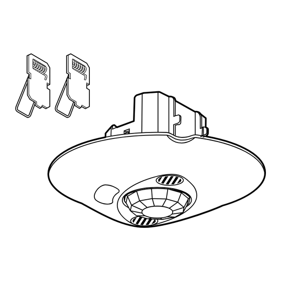
PIR+US ceiling mount sensors
(DALI)
1. USE
DALI sensor Cat. No. 0 489 35 is a device which measures the daylight
level and detects presence of people using dual technology (passive
infrared and ultrasonic (PIR + US)).
It can be surface-mounted on a concrete ceiling using box
Cat. No. 0 488 75, or flush-mounted directly in a suspended ceiling using
claws or in a flush-mounting box Cat. No. 0 800 31.
It is suitable for indoor workspaces such as offices, meeting rooms,
classrooms, etc and it can be used on its own or in combination with
DALI power supply/wiring unit Cat No. 0 488 76.
This sensor can manage up to 2 groups of dimmer ECGs, "window"
and "corridor" type (containing a maximum of 64 ECGs), for which it is
possible to configure an offset light level.
If it is used in combination with DALI power supply/wiring unit
Cat No. 0 488 76, it can manage up to three ECG groups (64 ECGs max).
These groups are made up as follows: 2 "window" and "corridor" groups
which can be used to dim the lighting, for which it is possible to set a
light level offset, and a "display board" group which can only be switched
ON/OFF.
This sensor is fully configured using configuration tool Cat. No. 0 882 30/
BMSO4001 with which it is possible to:
- Distribute DALI ECG addresses
- Pair DALI ECGs with their sensor and their group (window, corridor or
display board)
- Define the light level offset between the "window" group and the
"corridor" group
- Designate Master and Slave sensors
- Define the standby level when there is no detection
- Define the standby time
- Configure all the other sensor settings (for example, daylight setpoint,
time the lighting remains on after detection, choice of detection
technology, operating mode, etc.)
DALI sensor Cat. No. 0 489 35 is powered with 16 VDC by the DALI bus.
A DALI power supply Cat No. 0 035 15 or 0 035 13 can supply this
voltage to the DALI BUS with a maximum of 200 mA, and the DALI unit
Cat No. 0 488 76 also acts as the bus power supply.
Technical data sheet: S000088482EN-1
2. TECHNICAL CHARACTERISTICS
Voltage: 12-20 V=
Consumption: 25 mA
Wiring:
2
- Power: 2 x 2.5 mm
DALI < 1.5 mm
2
Usage temperature: -5°C to +45°C
Storage temperature: -20°C to +70°C
Impact resistance: IK04
Penetration by solid and liquid matter: IP20
Weight: 115 g
PIR sensor
Light level cell
TEST button
Detection LED
Updated:
Cat. No(s): 0 489 35
CONTENTS
1.
Use . . . . . . . . . . . . . . . . . . . . . . . . . . . . . . . . . . . . . .1
2.
Technical characteristics . . . . . . . . . . . . . . . . .1
3.
Installation. . . . . . . . . . . . . . . . . . . . . . . . . . . . . . .2
4.
Dimensions . . . . . . . . . . . . . . . . . . . . . . . . . . . . . .3
5.
Connection . . . . . . . . . . . . . . . . . . . . . . . . . . . . . .3
6.
Operation. . . . . . . . . . . . . . . . . . . . . . . . . . . . . . . .5
7.
Settings. . . . . . . . . . . . . . . . . . . . . . . . . . . . . . . . . .5
8.
Performance . . . . . . . . . . . . . . . . . . . . . . . . . . . . .7
9.
Care . . . . . . . . . . . . . . . . . . . . . . . . . . . . . . . . . . . . .7
10.
Standards. . . . . . . . . . . . . . . . . . . . . . . . . . . . . . .8
11.
Troubleshooting . . . . . . . . . . . . . . . . . . . . . . . .8
US sensor
DALI configuration red
LED
IR transmission/
reception cell
Created: 02/01/2017
Page
1/8
Advertisement

Related Manuals for LEGRAND 0 489 35


Summary of Contents for LEGRAND 0 489 35
- Page 1 Detection LED DALI sensor Cat. No. 0 489 35 is powered with 16 VDC by the DALI bus. A DALI power supply Cat No. 0 035 15 or 0 035 13 can supply this voltage to the DALI BUS with a maximum of 200 mA, and the DALI unit IR transmission/ Cat No.
-
Page 2: Installation
PIR+US ceiling mount sensors Cat. No(s): 0 489 35 (DALI) 3. INSTALLATION 3. INSTALLATION (CONTINUED) 3.1 Sensor location 3.3 Mounting 0.3 to Ø 68 Ø 65 20 mm 3.2 Recommended light exposure 3.4 Recommended light exposure 2.5 m... - Page 3 PIR+US ceiling mount sensors Cat. No(s): 0 489 35 (DALI) 4. DIMENSIONS 5. CONNECTION (CONTINUED) 5.2 Wiring with several sensors Cat. Nos. 0 035 13/15 200 mA max. 5. CONNECTION 5.1 Wiring with a single sensor: Cat. Nos. 0 035 13/15 200 mA max.
- Page 4 PIR+US ceiling mount sensors Cat. No(s): 0 489 35 (DALI) 5. CONNECTION (CONTINUED) 5. CONNECTION (CONTINUED) 5.3 Wiring with several sensors and one control unit: 5.4 Wiring with several sensors, one control unit and a DALI unit Cat. No. 0 488 76...
-
Page 5: Operation
PIR+US ceiling mount sensors Cat. No(s): 0 489 35 (DALI) 6. OPERATION 7. SETTINGS (CONTINUED) 6.1 TEST function 7.1 Detection settings (continued) Auto on/Auto off mode: The lighting switches on automatically: - On detection of presence if the natural light level is insufficient... - Page 6 PIR+US ceiling mount sensors Cat. No(s): 0 489 35 (DALI) 7. SETTINGS (CONTINUED) 8. PERFORMANCE 7.2 Light level settings 8.1 PIR - Motion detection Advanced mode: Height Calibration: The ambient light level measured with a luxmeter must then be transmitted to the sensor.
- Page 7 PIR+US ceiling mount sensors Cat. No(s): 0 489 35 (DALI) 8. PERFORMANCE (CONTINUED) 8. PERFORMANCE (CONTINUED) 8.2 PIR - Presence detection (continued) 8.4 US - Presence detection Low sensitivity Medium sensitivity (25%) (50%) Height Ø (m) surface (m ) Ø...
-
Page 8: 11. Troubleshooting
PIR+US ceiling mount sensors Cat. No(s): 0 489 35 (DALI) 10. STANDARDS Directive: EC Installation standards: NFC 15-100 Product standards: NF EN 50428 Environmental standards: - European directive 2002/96/EC: WEEE (Waste Electrical and Electronic Equipment) - European directive 2002/95/EC: RoHS (Restriction of Hazardous Substances)
Need help?
Do you have a question about the 0 489 35 and is the answer not in the manual?
Questions and answers