Table of Contents
Advertisement
Quick Links
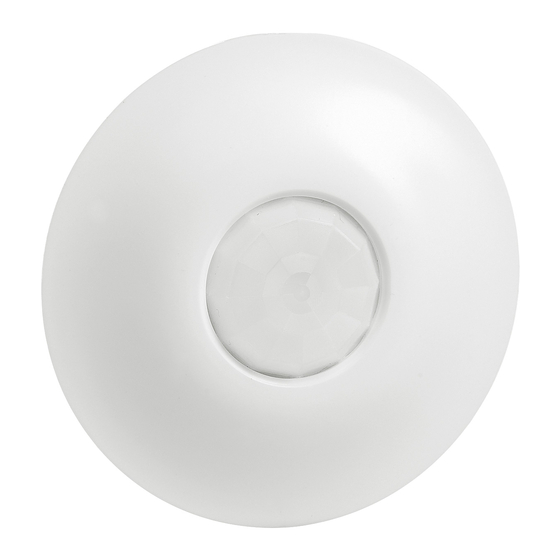
PIR switch sensor
1. USE
This device allows a light source to be controlled automatically through
the detection of movement in the surveillance zone.
It is equipped with a "presence" output for ventilation or lighting
control. This output is separate from the level of light.
Motion sensor with 360° detection angle.
Detection type: infrared (PIR)
Mounting type: ceiling
2. TECHNICAL CHARACTERISTICS
Voltage: 100 - 240 V~
Frequency: 50/60 Hz
No-load power consumption: 0.8 W
Output via normally open contact connected to the phase
Wiring: 2 x 2.5 mm
2
Drilling diameter: 85 mm without flush-mounting box
85 mm with flush-mounting box
Weight: 114 g
Impact resistance: IK04
Penetration by solid and liquid matter: IP20 (unmounted)
Usage temperature: - 5°C to + 45°C
Storage temperature: - 20°C to + 70°C
1
2
230 V~ 2000 W
1000 VA
8.5 A
110 V~ 1000 W
500 VA
1 - Halogen bulb
2 - ELV halogen bulb with separate electronic ballast
3 - ELV halogen bulb with separate ferromagnetic ballast
4 - Fluorescent tube with separate ferromagnetic ballast
5 - ELV fluorescent tube with separate electronic ballast
6 - Compact fluorescent bulb with built-in electronic ballast
7 - Compact fluorescent bulb with separate ferromagnetic ballast
8 - Compact fluorescent bulb with separate electronic ballast
9 - LED bulb
10 - Contactor
11 - Motor
Technical data sheet: S000074405EN-2
IP41 (mounted)
3
4
5
10x(2x36 W)
500 VA
4.3 A
4.3 A
5x(2x36 W)
250 VA
Updated: 10/02/2016
2. TECHNICAL CHARACTERISTICS (continued)
Cover removed
LEARN button
LEARN LED
Green
programming
indicator
Sensor/PIR
sensor
6
7
8
1000 VA
500 VA
2.1 A
4.3 A
500 VA
250 VA
230 V~
2000 W
110 V~
1000 W
2 A max.
U ≤ 30 V=
Catalogue Number(s): 0 488 04
CONTENTS
1. Use . . . . . . . . . . . . . . . . . . . . . . . . . . . . . . . . . . . . .1
2. Technical characteristics . . . . . . . . . . . . . . . .1
3. Dimensions. . . . . . . . . . . . . . . . . . . . . . . . . . . . .2
4. Connection . . . . . . . . . . . . . . . . . . . . . . . . . . . . .2
5. Installation . . . . . . . . . . . . . . . . . . . . . . . . . . . . .4
6. Removal . . . . . . . . . . . . . . . . . . . . . . . . . . . . . . . .4
7. Operation . . . . . . . . . . . . . . . . . . . . . . . . . . . . . .5
8. Settings . . . . . . . . . . . . . . . . . . . . . . . . . . . . . . . .6
9. Performance . . . . . . . . . . . . . . . . . . . . . . . . . .7
10. Care . . . . . . . . . . . . . . . . . . . . . . . . . . . . . . . . . .8
11. Standards And Approvals . . . . . . . . . . . . . . . .8
12. Troubleshooting . . . . . . . . . . . . . . . . . . . . . . . .8
Light level cell
IR receiver LED
(for configuration
tool or remote
control)
Protective cover
9
2.1 A I max. ≤ 2A
8.5 A
I max. ≤ 2A
Created: 18/01/2013
Page
IR transmission LED
(for configuration
tool)
Green
detection
indicator
1/8
Advertisement
Table of Contents

Subscribe to Our Youtube Channel
Related Manuals for LEGRAND 0 488 04


Summary of Contents for LEGRAND 0 488 04
- Page 1 PIR switch sensor Catalogue Number(s): 0 488 04 CONTENTS Page 1. Use ........1 2.
- Page 2 PIR switch sensor Catalogue Number(s): 0 488 04 3. DIMENSIONS 4. CONNECTION Without protective cover Number of terminals: 6 Type of terminals: automatic Terminal capacity: 2 x 2.5 mm Stripping length: 8 mm 4.1 Wiring with auxiliary control: 8.5 A With protective cover 100 m max.
- Page 3 PIR switch sensor Catalogue Number(s): 0 488 04 4. CONNECTION (continued) 4.2 Wiring for a single load connected in parallel 8.5 A 100 m 4.3 Wiring for several loads connected in parallel 8.5 A 8.5 A 8.5 A 100 m...
- Page 4 PIR switch sensor Catalogue Number(s): 0 488 04 5. INSTALLATION 5. INSTALLATION (continued) 5.1 Sensor positioning Ø 85 Ø 85 0.3 to 20 mm 5.2 Recommended light exposure 2.5 m 6. REMOVAL Technical data sheet: S000074405EN-2 Updated: 10/02/2016 Created: 18/01/2013 CONTENTS...
- Page 5 PIR switch sensor Catalogue Number(s): 0 488 04 7. OPERATION 7. OPERATION (continued) Manual ON/Automatic OFF mode 6.1 Several sensors connected to a single load Pressing the auxiliary control allows the load to be switched on or off manually. If the control is not pressed, the sensor will cut off the load at the end of the time delay or when the light level threshold has been reached.
- Page 6 PIR switch sensor Catalogue Number(s): 0 488 04 8. SETTINGS 8. SETTINGS (continued) 8.1 Detection parameters 8.2 Light parameters Sensor parameter Default Modifiable Configuration Sensor parameter Default Modifiable Configuration value parameters tools value parameters tools 0 882 30 0 882 35 0 882 30 0 882 35 3, 5, 10, 15, 20 min...
- Page 7 PIR switch sensor Catalogue Number(s): 0 488 04 9. PERFORMANCE 9. PERFORMANCE (continued) 9.1 Walk-through 9.2 Presence Height Height 1.2 m (PIR) (PIR) Ø Ø Sensitivity Sensitivity Sensitivity Sensitivity Low (25%) Medium (50%) Low (25%) Medium (50%) Ø (m) Ø (m) Ø...
- Page 8 PIR switch sensor Catalogue Number(s): 0 488 04 10. CARE 11. STANDARDS Keep the lens clean. Directive: CE Clean the surface with a cloth. Product standards: IEC 60669-2-1 Do not use acetone, tar-removing cleaning agents or trichloroethylene. Environmental standards: Resistant to the following products: - Hexane (EN 60669-1)
Need help?
Do you have a question about the 0 488 04 and is the answer not in the manual?
Questions and answers