Table of Contents
Advertisement
Climate Logic
Get more done
TM
Introduction
The Irritrol Climate Logic
wireless weather sensor system
TM
transforms your automatic irrigation control system into
a high-efficiency, water resource-management center.
Compatible with remote-ready Irritrol and Toro controllers,
Climate Logic automatically regulates watering duration
corresponding to real-time weather conditions and specific
geographic and local weather profile information provided on
a region-specific Setup Card. In addition, integral rain and
freeze sensing further reduce wasteful, unnecessary irrigation
and icing conditions.
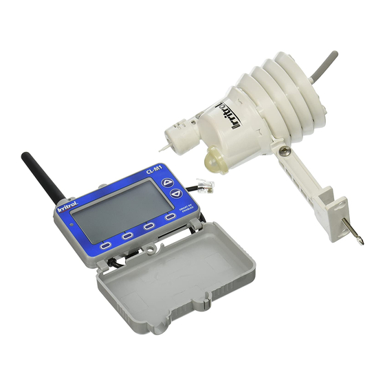
Your Climate Logic system consists of a self-contained,
Weather Sensor/Transmitter that continuously monitors
current air temperature, solar radiation and precipitation.
This data is transmitted at regular intervals throughout the
day to the Receiver Module; linked directly to your controller's
remote control port. Each day, Climate Logic calculates and
adjusts the programmed station run time duration to the
amount required for the next automatic watering cycle.
The Climate Logic system is designed for easy installation,
setup and use. To take full advantage of the features and
capabilities provided by the Climate Logic system, take a
moment to review the detailed information provided within
this guide.
To answer any questions you may have regarding the Climate
Logic system, or any Irritrol product, please contact an Irritrol
Customer Service representative at (U.S.) 1-800-634-8873 or
(E.U.) +39 0765 40191.
L = 8" x W = 6", Grayscale, Printed on regular bond paper.
Wireless Weather Sensor System
TM
User's Guide
Quick Start Guide ................................................................... 2-3
System Components at a Glance ..................................... 4-5
CL-M1 Receiver Module .................................................. 4
CL-W1 Wireless Weather Sensor .................................. 5
Climate Logic System Installation ................................... 6-11
Receiver Module Installation and Setup .................. 6-8
Weather Sensor Installation and Setup .................... 9-11
Climate Logic System Operation ...................................... 12-19
Control Feature Setup Options .................................... 12
Setup Menu Options ........................................................ 13
Utility Menu Options ........................................................ 14
Water Adjust Feature ........................................................ 15
Rain/Freeze Sensor Control Feature .......................... 16
Water History Review Feature ...................................... 17
Weather Sensor Identification Feature ..................... 18
Control System Synchronization ................................. 19
Remote PIN Setup .............................................................. 19
Weather Sensor Battery Replacement ........................... 20
Specifications ........................................................................... 21
FCC Information ...................................................................... 22
Advertisement
Table of Contents

Related Manuals for Irritrol Climate Logic

Summary of Contents for Irritrol Climate Logic
-
Page 1: Table Of Contents
Receiver Module; linked directly to your controller’s Weather Sensor Installation and Setup ....9–11 remote control port. Each day, Climate Logic calculates and Climate Logic System Operation ........12–19 adjusts the programmed station run time duration to the Control Feature Setup Options ........ -
Page 2: Quick Start Guide
Step 6 The Quick-Start guide provides the essential steps required to properly install and setup the Climate Logic system in the most direct route possible. As needed, refer to the detailed information on the page number listed with each step. - Page 3 See page 9. 11/16 Step 7 – Press the sensor Test Pin again to confirm signal reception at the Receiver Module. The CLIMATE LOGIC receiver’s red LED will turn on momentarily when the signal is received. Press the BYPASS Dry Out Remain 12h...
-
Page 4: System Components At A Glance
7 – Connector Cable: Plugs into controller’s remote control receptacle. 8 – Multifunction Keys: Key function is configured for each screen as required. 9 – LED Status Indicator: Remains On when irrigation is suspended; flashes when bypassed. Climate Logic at a Glance... -
Page 5: Cl-W1 Wireless Weather Sensor
5 – QuickClip Mounting Bracket Convenient QuickClip mounting bracket provides quick and easy Weather Sensor installation. 6 – Temperature Sensor (not shown) 7 – RF Transmission LED (not shown) 8 – Antenna Wire Climate Logic at a Glance... -
Page 6: Climate Logic System Installation
Note: By default, Climate Logic modifies the run time of stations assigned only to Program A. To include • Pr Program B, or Programs B and C, see page 13. - Page 7 4. The Receiver Module will automatically* synchronize time and date with the host controller upon initial power-up. Main Menu * Note: Does not apply to TMC-212 controller. Timer Clock 5. Verify that the time and date are synchronized correctly. Location Remote Setup Utility...
- Page 8 6. With the cover closed, CLIMATE LOGIC CLIMATE LOGIC CLIMATE LOGIC CLIMATE LOGIC CLIMATE LOGIC insert the Climate Logic – – – No Rain - Irrigation CLIMATE LOGIC Setup Card into the MUST SET LOCATION 1:15 11/16 MENU MENU SET LOC...
-
Page 9: Weather Sensor Installation And Setup
Weather Sensor Installation and Setup Important: The Climate Logic Weather Sensor is shipped with the battery circuit deactivated. To initially activate the sensor prior to installation, press and hold the Test Pin for 10–15 seconds. A red LED, viewable from the lower vent area, will illuminate twice after 10 seconds (if not already active). - Page 10 After a brief time, the current temperature, watering history effe CLIMATE LOGIC graph line, and signal-strength bars will be displayed. Note: A single Weather Sensor can be paired to multiple Receiver inst Modules when additional Climate Logic systems are installed • St 2:32 within reception range. 11/16 MENU 2.
- Page 11 3. The Climate Logic system is designed to provide effective wireless communication in most applications. Loss of range can result from interference in the signal path. To verify signal reception from the selected installation site, perform the following test: • Start a manual watering operation of a zone that can be seen from the installation site.
-
Page 12: Climate Logic System Operation
Control Feature Setup Options Setu Climate Logic System Operation The Climate Logic system control features, accessible through the Setup and Utility menu screens, The foll determine how and when the system displays information and performs various functions that regulate menu ( weather-defined automatic irrigation. -
Page 13: Setup Menu Options
Average Percent Days: This setting defines how many days of compiled weather data are used to calculate the current watering adjustment % factor. By default, Climate Logic compiles data from the three previous y, and days to provide a moderately smooth adjustment factor. -
Page 14: Utility Menu Options
Freeze Temperature (threshold): The freeze sensor activation Default threshold can be adjusted from 39° F (4° C), (default) down to 35° F all user ET Setup (2° C), or increased to 45° F (7° C), in 2° increments. the fact 3 of 3 ing Loc Important: Freeze sensor operation should be used only when the... -
Page 15: Water Adjust Feature
Default ( ): The Default utility feature enables DEFAULT _ ENTER all user-defined setup parameters to be either erased and reset to the factory default settings, or a complete system reset includ- Reset To ing Location, History, and Sensor Pairing.* Factory Defaults? key to reset to the Factory Default settings. -
Page 16: Rain/Freeze Sensor Control Feature
Menu. LED indicator will blink continuously. Watering operations can CLIMATE LOGIC The His resume, however the Climate Logic system will remain in the each da Bypass mode until the system automatically resets after the the bot Dry-out duration times out. -
Page 17: Water History Review Feature
Water History Review Feature CLIMATE LOGIC The Climate Logic system tracks and records the daily adjust- E LOGIC ment factor for a rolling, two-year period. A one-month snap- shot is represented by the small bar graph on the Home screen. -
Page 18: Weather Sensor Identification Feature
Weather Sensor Identification Feature Cont Sensor Setup Within the Sensor Setup screen, the Weather Sensor ID can be The Rec easily viewed, and pairing removed/replaced as needed. Logic sy ET Sensor ID: 0065157 synchro • From the Home screen, select the Main Menu Sensor option The ID number of the currently • From MENU_SENSOR_ENTER). -
Page 19: Control System Synchronization
. The controller make, model and MENU_TIMER_ENTER) software version will be displayed. Timer • Press the key as needed to update the controller REFRESH IRRITROL Rain Dial information. Version: 03.00.02 • Press the (Detect) key to access the current controller DECT EXIT DECT REFRESH time and date setting. -
Page 20: Weather Sensor Battery Replacement
Weather Sensor Battery Replacement Spec In normal operating conditions, the Weather Sensor’s single, 9V-Alakaline battery can provide service up Weathe to five years. A loss of signal will result from a weak battery condition. Replace the battery as follows: • 2.75” • The battery is stored in the upper half of the 7 cm sensor housing. -
Page 21: Specifications
Specifications ce up Weather Sensor/Transmitter Receiver Module • Compatible with Remote-ready Irritrol and Toro • 2.75” W x 5” H x 6.25” D (over bracket) Controllers and CL Series Handheld Remote 7 cm W x 12.7 cm H x 15.9 cm D (over bracket) • Input Power (from controller): 5v DC • Battery: 9V-Alkaline, up to 5-year duration • LCD Screen Dimensions: • Antenna Wire: 2.5” W x 1.25” H 1.5” L x 0.192 Dia. 6.35 cm W x 3.18 cm H 3.81 cm L x 4.8 mm Dia. • LCD Contrast Adjustment • RF Reception Range: Up to 1000’ (304 m) LOS • Dimensions: • Operating Temperature: 14–140 °F (-10°–60° C) 3.25” H (5.375” w/antenna) x 4.125” W x 0.75” D • Rain Sensing Method: Industry-standard, hygro- 8.26 cm H (13.16 cm w/antenna) x 10.48 cm W x scopic, stacked-disc style w/adjustable threshold 1.9 cm D... -
Page 22: Fcc Information
Notes FCC Information This equipment generates and uses radio frequency energy and if not installed and used properly, that is, in strict accordance with the manufacturer’s instructions, may cause interference to radio and television reception. It has been type tested and found to comply with the limits for a FCC Class B computing device in accordance with the specifications in Subpart J of Part 15 of FCC Rules, which are designed to provide reasonable protection against such interference in a residential installation. However, there is no guarantee that interference will not occur in a particular installation. - Page 23 Notes that is, evision device provide arantee o radio encour- on dif- ditional ommis- le from Notes...
- Page 24 The Water Saver® symbol accompanies each of our products that provide a significant water-savings opportunity. As you can see, the Climate Logic system proudly bears this distinctive symbol. © 2012 Irritrol • www.irritrol.com • Technical Service Support: U.S. 1-800-634-8873, E.U. +39 0765 40191 • P/N 373-0771 Rev. A...
Need help?
Do you have a question about the Climate Logic and is the answer not in the manual?
Questions and answers