Table of Contents
Advertisement
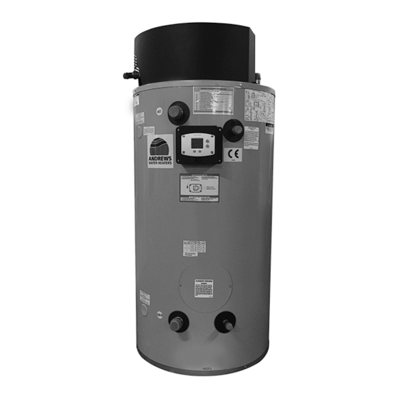
HIflo EVO range - Gas fired storage water heaters for natural gas & LPG
HF 30/300, HF 48/300, HF 65/300, HF 48/380, HF 65/380
Please read and understand these instructions before commencing installation and leave this manual with the customer for future reference.
Andrews. Built to perform.
Issue 4 21042918
Advertisement
Table of Contents


Need help?
Do you have a question about the HIflo EVO HF 30/300 and is the answer not in the manual?
Questions and answers