Toshiba 4818-T10 User Manual
Hide thumbs
Also See for 4818-T10:
- Service manual (22 pages) ,
- Operating system installation manual (3 pages) ,
- User manual (42 pages)
Table of Contents
Advertisement
Advertisement
Table of Contents

Related Manuals for Toshiba 4818-T10


Summary of Contents for Toshiba 4818-T10
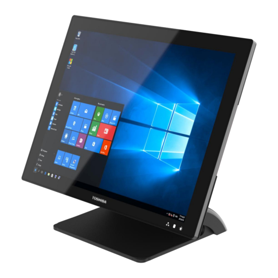
- Page 1 Toshiba Global Commerce Solutions User’s Manual 4818-T10...
-
Page 2: Table Of Contents
Contents Contents ......................2 Safety ........................3 1. Hardware Setup ..................... 4 1.1. Packing Contents ......................4 1.2. Quick Tour ........................5 1.3. Basic Peripherals Installation ..................6 1.4. Replacing M.2 Storage ....................14 1.5. Replacing Memory Module ..................15 1.6. -
Page 3: Safety
Safety Before installing this product, read Safety Information. Antes de instalar este produto, leia as Informações de Segurança. Pred instalací tohoto produktu si prectete prí rucku bezpecnostní ch instrukcí . Læ s sikkerhedsforskrifterne, fø r du installerer dette produkt. Lees voordat u dit product installeert eerst de veiligheidsvoorschriften. Ennen kuin asennat tämän tuotteen, lue turvaohjeet kohdasta Safety Information. -
Page 4: Hardware Setup
Hardware Setup 1.1. Packing Contents 1. Device X 1 2. RJ50 to DB9 COM port adapter cable X 2 3. Power Adapter X 1 4. Manual DVD X 1... -
Page 5: Quick Tour
1.2. Quick Tour Front View LED Indicator: The Power indicator will glow green when power is on. The Storage indicator will blink green when the SATA storage is accessed. The LAN indicator will blink green when transferring data through the LAN. Back View Notices For N on-wir eless Pr oduct... -
Page 6: Basic Peripherals Installation
Back Panel I/O A. B. I/O Functions: 1 x 3.5mm Combo Audio jack 1 x mini-DisplayPort C. 2 x RS232 by RJ50 (COM4 / COM3), include RJ50 to DB9 convert cable D. 2 x RS232 by DB-9 (COM2 / COM1) 2 x 12V PoweredUSB 1 x 24V PoweredUSB G. - Page 7 Power Adapter Important! Plug the AC adapter into the Point Of Sale (POS), and then connect to the mains power supply. Connect the 4-pin output jack of the adapter to the DC 24V jack on the back panel of the device. USB Mouse, USB Keyboard and USB Optical Disk Driver (ODD) Connect your USB Mouse, USB Keyboard and USB Optical Disk Driver (ODD) to USB ports on the back panel of the device.
- Page 8 NOTE: The USB male length needs to be less than 57mm. LAN Cable Connect one end of RJ-45 LAN cable to the LAN port on the back panel of the device, and the other end to your internet device. Cash Drawer Connect one end of RJ-12 cable to the Cash Drawer port on the back panel of the device, and the other end to your cash drawer.
- Page 9 2nd Display 1. Remover the top peripheral mounting hole cover from the device and pull out the connector from the device. 2. Adjust the hinge of the custom monitor (2nd display), and then connect to the device as shown below. NOTE: 2nd display cable need remove the connector cover first.
- Page 10 5. For the current main display touch function work, you may need to perform the following steps to correct the mapping. Run "Tablet PC Settings" on the Windows Control Panel and click the "Settings" button. Following the display instruction, manually touching the touch screen twice, then the main touch will operate correctly on the main display.
- Page 11 2. Adjust the hinge of the custom monitor (customer VFD), and then connect to the device as shown below. NOTE: VFD cable need remove the connector cover first. 3. Mount the customer display to the device and tighten the two PHILLIPS M3 screws as shown below.
- Page 12 MSR + iButton NOTE: MSR + iButton only can be installed on the right side. 1. Remove the right side peripheral cover from the system. 2. Install the adaptor.
- Page 13 3. Connect the cable of the MSR + iButton assembly to the system. NOTE: MSR + iButton cable need remove the connector cover 4. Combine the MSR + iButton into side peripheral door of system, tighten the two PHILLIPS M3 screws to fix the MSR assembly as shown below. 5.
-
Page 14: Replacing M.2 Storage
1.4. Replacing M.2 Storage 1. Remove the cable cover and slightly uplift first. 2. Remove all IO cables. (LAN, 24V /12V PUSB, RS232, CD & USB) 3. Release 2 thumb screws of System board Box then slightly slide down 4. Hold system board box with one hand and slightly uplift the pulling tab with another hand 5. -
Page 15: Replacing Memory Module
1.5. Replacing Memory Module 1. Follow Section 1.4 step 1 to step 4, then can get system board box open. 2. Release the two ejectors on the slot by pushing them and remove the memory module from the slot. 3. Align and insert the new memory module in the slot and push both ends down until the ejectors snap into place. -
Page 16: Adjust Tilting Angle
1.6. Adjust Tilting Angle The tilt angle of the operator’s display can be adjusted freely from 25° to 90°. Hold both sides of the LCD frame, and slowly push the display upward/ downward to your best angle. 25° 90° 1.7. Turn On The Device 1. -
Page 17: I/O Definition
I/O Definition Please refer the detailed technical information about all I/O ports as followings. 2.1. Serial Port COM1/COM2 by direct DB9 connector, COM3/COM4 by RJ50 connector with convert to DB9 cable. DB9 pin9 with NA/5V/12V by BIOS selection. RS-232 Description Description NA / 5V /12V Notices For N on-wir eless Pr oduct... -
Page 19: Cash Drawer
2.2. Cash Drawer Description Description D_OUT0 D_OUT1 D_IN Cash Drawer Control The Cash Drawer Controller use one I/O address to control the Cash Drawer. Register Location: 48Ch Attribute: Read / Write Size: 8-bit R: Read / W: Write / X: Reserved Reserved Cash Drawer “DOUT bit0”... - Page 20 Cash Drawer Control Command Example (Use Debug.EXE program under DOS) Command Cash Drawer O 48C 04 Opening O 48C 00 Allow to close Set the I/O address 48Ch bit2 =1 for opening Cash Drawer by “DOUT bit0” pin control. ...
-
Page 21: Preparing Your Pos Pc For Wall-Mounting
Preparing Your POS PC For Wall-mounting 3.1. What You Need 1. A PHILLIPS M3 screwdriver and flathead screwdriver (magnetic-tipped recommended) 2. A PHILLIPS M4 screwdriver and flathead screwdriver (magnetic-tipped recommended) 3. Antistatic wrist strap and conductive foam pad to stand on while working on the POS PC (recommended) 3.2. -
Page 22: Removing The Pos Pc Stand
3. After the system has completely shut down, disconnect the power adapter from of the POS PC. 4. Disconnect all other attached cables from the back of the POS PC. 3.4. Removing The POS PC Stand 1. Remove the cable cover from the POS PC. Release 2 thumb screws of System board Box then slightly slide down. - Page 23 3. Use a Phillips M3 screwdriver to remove the five screws on the bracket plate. 4. Lift the stand away from the touch monitor Notices For N on-wir eless Pr oduct...
- Page 24 5. Place back the System board Box using a Phillips screwdriver to tighten the two screws. 6. Align the cable cover to the System board Box and snap it back into place. Make sure that there are no gaps between the System board Box and the cable cover.
-
Page 25: Installing The Vesa
3.5. Installing The VESA 1. Attach the VESA wall-mounting plate to the back of the POS PC, using a Phillips M4 screwdriver to tighten the four screws. It should take about 5–10 turns of the screwdriver to secure the screws. CAUTION: The VESA wall-mounting plate is not accessory. -
Page 26: Reinstalling The Pos Pc Stand
Reinstalling The POS PC Stand 4.1. What You Need 1. A PHILLIPS M3 screwdriver and flathead screwdriver (magnetic-tipped recommended) 2. A PHILLIPS M4 screwdriver and flathead screwdriver (magnetic-tipped recommended) 3. Antistatic wrist strap and conductive foam pad to stand on while working on the POS PC (recommended) 4.2. -
Page 27: Reinstalling The Pos Pc Stand
3. After the system has completely shut down, disconnect the power adapter from of the POS PC. 4. Disconnect all other attached cables from the back of the POS PC. 4.4. Reinstalling The POS PC Stand 1. Use a Phillips M4 screwdriver remove wall-mounting back four screws. 2. - Page 28 Release 2 thumb screws of System board Box then slightly slide down. 4. Put back the stand away from the touch monitor.
- Page 29 5. using a Phillips M3 screwdriver to tighten the five screws. It should take about 5– 10 turns of the screwdriver to secure the screws. 6. Place back the System board Box using a Phillips screwdriver to tighten the two screws.
- Page 30 7. Align the cable cover to the System board Box and snap it back into place. Make sure that there are no gaps between the System board Box and the stand cover.
-
Page 31: Specification
Specification 5.1. Basic Specification Main Board Intel® Bay Trail-Mobile/Desktop SoC Processor: - Celeron® J1900 (4 cores, up to 2.42 GHz, TDP 10 Watt) System Memory SO-DIMM DDR3L 1067/1333MHz x 1, Max. 8GB Graphic Intel® HD Graphics Thermal Solution Fan-less BIOS Phoenix uEFI BIOS Windows 7, WES 7, POSReady 7 Windows 8.1, Windows Embedded 8.1 Standard/Industry Retail... -
Page 32: Options
Certifications CE / FCC / VCCI / WEEE / RoHS Dimension (W x D x H) 360 x 193 x 316 mm (14.2 x 7.6 x 12.4 inch) Net Weight 5 kg, 11 lb Gross Weight 6.5 kg, 14 lb Environmental 0°C ~ 40°C Operating Temperature... -
Page 33: Dimension
Dimension (mm) Notices For N on-wir eless Pr oduct... -
Page 34: Copyrights
Web sites. The materials at those Web sites are not part of the materials for this Toshiba Global Commerce Solutions product and use of those Web sites is at your own risk. - Page 35 Global Commerce Solutions products. Questions on the capabilities of non-Toshiba Global Commerce Solutions products should be addressed to the suppliers of those products. This information is for planning purposes only. The information herein is subject to change before the products described become available.
- Page 36 Mitgliedsstaaten und hält die Grenzwerte der EN 55032 Klasse A ein. Um dieses sicherzustellen, sind die Geräte wie in den Handbüchern beschrieben zu installieren und zu betreiben. Des Weiteren dürfen auch nur von der Toshiba Global Commerce Solutions empfohlene Kabel angeschlossen werden. Toshiba Global Commerce Solutions übernimmt keine Verantwortung für die Einhaltung der Schutzanforderungen, wenn...
- Page 37 Toshiba Global Commerce Solutions, Inc. Brand Manager - Europe, Middle East & Africa Z.1 Researchpark 160, 1731 Asse, Belgium Tel:33-6845-35093 e-mail: cthery@toshibagcs.com Generelle Informationen: Das Gerät erfü llt die Schutzanforderungen nach EN 55024 und EN 55032 Klasse A. Australia and New Zealand Class A statement Attention: This is a Class A product.
- Page 38 This is for any areas other than home. Taiwan Class A compliance statement Taiwan contact information Toshiba Global Commerce Solutions Taiwan Product Service Contact Info: Toshiba Global Commerce Solutions, Inc. Rm. 1, 5F., No.3-2, Park St., Nangang Dist., Taipei City, Taiwan...
- Page 39 (TI) que reciclen responsablemente sus equipos cuando éstos ya no les sean útiles. Toshiba Global Commerce Solutions dispone de una serie de programas y servicios de devolución de productos en varios paí ses, a fí n de ayudar a los propietarios de equipos a reciclar sus productos de TI.
- Page 40 Toshiba Global Commerce Solutions representative. Disposal of IT products should be in accordance with local ordinances and regulations. Battery safety Caution: Risk of explosion if battery is replaced by an incorrect type. Dispose of used batteries according to the instructions.
- Page 41 Customer participation is important to minimize any potential effects of batteries and accumulators on the environment and human health due to the potential presence of hazardous substances. For proper collection and treatment, contact your local Toshiba Global Commerce Solutions representative.
- Page 42 Toxics/Reducing-recycling-waste/Electronics or telephone the Washington Department of Ecology at 1-800-Recycle. Trademarks The following are trademarks or registered trademarks of Toshiba, Inc. in the United States or other countries, or both: Toshiba The Toshiba logo The following are trademarks of Toshiba Global Commerce Solutions in the United States or...
Need help?
Do you have a question about the 4818-T10 and is the answer not in the manual?
Questions and answers