Toshiba 4818-T10 Service Manual
Hide thumbs
Also See for 4818-T10:
- Operating system installation manual (3 pages) ,
- User manual (42 pages) ,
- User manual (42 pages)
Table of Contents
Advertisement
Advertisement
Table of Contents

Related Manuals for Toshiba 4818-T10


Summary of Contents for Toshiba 4818-T10
- Page 1 Toshiba Global Commerce Solutions Service Manual 4818-T10...
-
Page 2: Copyrights
Copyrights © 2018 All rights reserved. The information in this document is subject to change without prior notice in order to improve reliability, design and function and does not repre sent a commitment on the part of the manufacturer. This document contains proprietary information protected by copyright. All rights are reserved. -
Page 3: Table Of Contents
Contents ....................3 Safety ...................... 4 1. 4818-T10 Product Overview ............5 2. Before You Start ................6 3. 4818-T10 Field Replaceable Unit ............ 7 4. Replacing Display Module .............. 8 5. Replacing System Board ..............10 6. Replacing Stand Base Unit ............13 7. -
Page 4: Safety
Safety Before installing this product, read Safety Information from accessory bag. Antes de instalar este produto, leia as Informações de Segurança. Pred instalací tohoto produktu si prectete prí rucku bezpecnostní ch instrukcí . Læ s sikkerhedsforskrifterne, fø r du installerer dette produkt. Lees voordat u dit product installeert eerst de veiligheidsvoorschriften. -
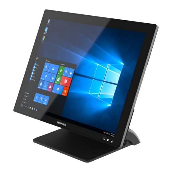
Page 5: 18-T10 Product Overview
4818-T10 Product Overview The Models 4818-T10 helps you provide fast, accurate customer service and manage your restaurant or store more efficiently. You can configure the systems to support a wide variety of both input/output (I/O) devices– everything from standard serial-attached devices to Universal Serial Bus (USB)-attached devices. System resources and the operating system might limit the use of ports. -
Page 6: Before You Start
Before You Start 1. Save and close all open files and exit all open applications. 2. Shut down your system. Push the Power button -> system Shut down. NOTE: If you are using a different operating system, see the documentation of your operating system for shut-down instructions. -
Page 7: 18-T10 Field Replaceable Unit
4818-T10 Field Replaceable Unit 1. User can purchase FRU from Toshiba Service Center located at EMEA, Asia and US if you desire to conduct the maintenance and Hardware Service with your own resource. Toshiba FRU PN Toshiba SMU PN Description... -
Page 8: Replacing Display Module
Replacing Display Module 1. Remove the cable cover, stand cover and slightly uplift first. 2. Remove all IO cables. (LAN, 24V /12V PUSB, RS232, CD,mDP & USB) 3. Release 2 thumb screws of System board Box then slightly slide down... - Page 9 4. Open the system box and detach the 50 pin LVSD cable (Section 5, step 1 to 5), and then remove system box ,Remove stand base unit by release the 5 screws from hinge plate then you can get Display Module off 5.
-
Page 10: Replacing System Board
Replacing System Board 1. Remove the cable cover and slightly uplift first. 2. Remove all IO cables. (LAN, 24V /12V PUSB, RS232, CD & USB) 3. Release 2 thumb screws of System board Box then slightly slide down 4. Hold system board box with one hand and slightly uplift the pulling tab with another hand 5. - Page 11 6. Loosen the seven screws in red circle as shown below by #2 Phillips screwdriver. 7. Remove four screws by 1.5 mm hexagon socket spanner then place the system board at ESD proof area 8. Remove m.2 storage by #1 Phillips screwdriver, memory, and speaker. Replace the new system board and re-install all accessories.
- Page 12 9. When install the system board, please notice the 50 pin LVDS connector and red dot direction as below instruction and slide in the connector tightly, otherwise, the connector and PCBA may be damaged.”...
-
Page 13: Replacing Stand Base Unit
Replacing Stand Base Unit 1. Remove the cable cover and slightly uplift first . 2. Remove all IO cables. (LAN, 24V /12V PUSB, RS232, CD & USB) 3. Release 2 thumb screws of System board Box then slightly slide down 4. -
Page 14: Replacing Memory Module
Replacing Memory Module 1. Follow Section 5 (step 1 to step 5) , then can get System board box open 2. Release the two ejectors on the slot by pushing them, and remove the memory module from the slot. 3. Align and insert the new memory module in the slot and push both ends down until the ejectors snap into place. -
Page 15: Replacing M.2 Storage
Replacing M.2 Storage 1. Follow Section 5 (step 1 to step 5) , then can get System board box open 2. Loosen screw with #1 Philips screw driver , and remove the M.2 from the slot. 3. Align and insert the new M.2 storage in the slot and push end down into place and tighten the screw... -
Page 16: Replacing The Coin Battery
Replacing the coin battery Follow Section 5 (step 1 to step 4) , then can get system board box open Removing the coin-cell battery 2.1 Disconnect the coin-cell battery cable from the system board 2.2 Note the location of the coin-cell battery and peel off from system board Replacing the coin-cell battery 3.1 Adhere the coin-cell battery to the system board. -
Page 17: Replacing Speaker
Replacing Speaker 1. Follow Section 5 (step 1 to step 5) , then can get system board box open 2. Remove from connector from system board and loosen the four screws by #1 Phillips screwdriver as shown below then remove the speaker from the system board box 3. -
Page 18: Replacing 10" 2Nd Display
Replacing 10” 2nd Display 1. Loosen the two PHILLIPS screws from 2 Display bracket 2. Remove the connector then can separate 2 Display from POS terminal 3. Recap the 2nd Display dummy cover if not change 2nd Display . 4. Please follow users manual to replace the FRU 10” 2nd Display... -
Page 19: Replacing 2X20 Vfd
Replacing 2X20 VFD 1. Loosen the two PHILLIPS screws from VFD bracket 2. Remove the connector then can separate VFD from POS terminal 3. Recap the 2 display dummy cover if not change VFD. 4. Please follow users manual to replace the FRU VFD... -
Page 20: Replacing Msr /Msr+Ibutton
Replacing MSR /MSR+iButton 1. Loosen the two PHILLIPS screws from MSR bracket 2. Remove the MSR from POS terminal and remove MSR bracket 3. Recap the MSR dummy cover if not change MSR 4. Please follow users manual to replace the FRU MSR... -
Page 21: System Board Connector /Function /Location
System Board Connector /Function /Location 14 13 Remark Connector Function DC-IN 24V IN RJ12 Cash Drawer LAN_CON1 LAN 1 Port USB30_1_2 USB 3.0 Port USB30_3_4 USB 3.0 Port 24V Power USB USB 2.0 Port 12V Power USB USB 2.0 Port 12V Power USB USB 2.0 Port DB9 COM1... - Page 22 Remark Connector Function RJ50_COM4 COM Port MINI_DP1 Display Port HPOUT HPOUT INT_SP Internal beeper FAN_1 MPCIE1/M.2 M.2 storage MPCIE2 WIFI/ MPCIE LVDS DP + COM +USB +SW + POWER LED DDR3 Memory EXT_SP External Speaker...
Need help?
Do you have a question about the 4818-T10 and is the answer not in the manual?
Questions and answers