Napoleon ALLURE Series Service Manual
Hide thumbs
Also See for ALLURE Series:
- Installation and operation manual (28 pages) ,
- Installation and operation manual (60 pages) ,
- Installation and operation manual (120 pages)
Table of Contents
Advertisement
Quick Links
ONLY QUALIFIED SERVICE TECHNICIANS SHOULD SERVICE AND REPAIR THIS APPLIANCE
ENGLISH
SERVICE MANUAL
CERTIFIED UNDER CANADIAN AND AMERICAN NATIONAL STANDARDS: CSA C22.2 No-46 / UL 2021
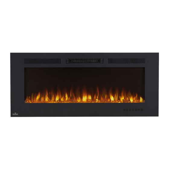
ALLURE / ALLURE PHANTOM
ELECTRIC FIREPLACE
ALLURE
SAFETY INFORMATION
NEFL32FH, NEFL42FH, NEFL50FH,
WARNING
NEFL60FH, NEFL72FH, NEFL100FH
!
If the information in these instructions
ALLURE PHANTOM
are not followed exactly, fi re or electrical
NEFL42FH-MT, NEFL50FH-MT, NEFL60FH-MT
shock may result causing property
damage, personal injury or loss of life.
Do not store or use gasoline or other fl ammable
vapors and liquids in the vicinity of this or any
other appliance.
Wolf Steel Ltd., 24 Napoleon Rd., Barrie, ON, L4M 0G8 Canada / 103 Miller Drive, Crittenden, Kentucky, USA, 41030
Phone (705)721-1212 • Fax (705)722-6031 • www.napoleonfi replaces.com • hearth@napoleonproducts.com
$10.00
W415-1698 / 12.20.16
Advertisement
Table of Contents

Related Manuals for Napoleon ALLURE Series


Summary of Contents for Napoleon ALLURE Series
- Page 1 Wolf Steel Ltd., 24 Napoleon Rd., Barrie, ON, L4M 0G8 Canada / 103 Miller Drive, Crittenden, Kentucky, USA, 41030 Phone (705)721-1212 • Fax (705)722-6031 • www.napoleonfi replaces.com • hearth@napoleonproducts.com $10.00...
-
Page 2: Table Of Contents
TABLE OF CONTENTS OPERATING INSTRUCTIONS OPERATING TOUCH DISPLAY PANEL AND REMOTE CONTROL REPLACEMENT PARTS WIRING DIAGRAM TROUBLESHOOTING FLAME LED TESTING 4.1.1 LED TESTING 4.1.2 MOTOR TESTING HEATER/BLOWER TESTING 4.2.1 BLOWER TESTING 4.2.2 HEATER TESTING HIGH LIMIT SWITCH TESTING SERVICE PREPARATION REPLACING COMPONENTS MOTOR AND ROTISSERIE REPLACEMENT CONTROL BOARD REPLACEMENT... -
Page 3: Operating Instructions
1.0 OPERATING INSTRUCTIONS WARNING WHILE THE APPLIANCE IS OPERATING DO NOT REMOVE THE GLASS PANEL. THIS WILL CAUSE THE REMOTE CONTROL AND TOUCH PANEL TO DISFUNCTION. Once the appliance has been plugged into a grounded electrical outlet, it is ready to operate. NOTE: Ensure the house circuit breakers for the power supply are turned on. -
Page 4: Replacement Parts
2.0 REPLACEMENT PARTS WARNING FAILURE TO POSITION THE PARTS IN ACCORDANCE WITH THIS MANUAL OR FAILURE TO USE ONLY PARTS SPECIFICALLY APPROVED WITH THIS APPLIANCE MAY RESULT IN PROPERTY DAMAGE OR PERSONAL INJURY. Contact your dealer for questions concerning prices and policies on replacement parts. Normally, all parts can be ordered through your Authorized dealer / distributor. - Page 5 NEFL32FH / NEFL42FH / NEFL50FH / NEFL60FH / NEFL72FH / NEFL100FH REF. NEFL32FH NEFL42FH NEFL50FH NEFL60FH NEFL72FH NEFL100FH DESCRIPTION W300-0226 W300-0224 W300-0227 W300-0228 W300-0229 W300-0230 FRONT GLASS W475-1192 W475-1185 W475-1193 W475-1194 W475-1195 W475-1196 ACRYLIC PLASTIC PANEL W405-0033 W405-0033 W405-0033 W405-0037 W405-0037 W405-0037 LED LIGHT...
-
Page 6: Wiring Diagram
3.0 WIRING DIAGRAM WARNING TURN OFF THE APPLIANCE COMPLETELY AND LET COOL BEFORE SERVICING. ONLY A QUALIFIED SERVICE PERSON SHOULD SERVICE AND REPAIR THIS ELECTRIC APPLIANCE. W415-1698 / 12.20.16... - Page 7 W415-1698 / 12.20.16...
- Page 8 W415-1698 / 12.20.16...
-
Page 9: Troubleshooting
4.0 TROUBLESHOOTING WARNING TURN OFF THE APPLIANCE COMPLETELY AND LET THE APPLIANCE COOL DOWN BEFORE SERVICING. IF YOU ARE EXPERIENCING ANY OF THESE ISSUES, UNPLUG APPLIANCE FROM THE POWER OR TURN OFF CIRCUIT BREAKER FOR 30 SECONDS TO FACTORY RESET THE APPLIANCE. FOR ALL HARDWIRED APPLIANCES, DO A VOLTAGE TEST TO ENSURE THAT THERE IS NO POWER RUNNING THROUGH THE UNIT. -
Page 10: Flame Led Testing
FLAME LED TESTING START HERE Perform LED testing Unplug the appliance Appliance is functioning accordingly. (Section 4.1.1) (if hardwired, turn off circuit breaker) Ensure the wires from the fl ame LED are not pinched, frayed, and are fi rmly connected on the PCB and fl ame LED Is the refl... - Page 11 FIGURES Fig. 3 Fig. 1 FLAME LED TERMINALS Fig. 2 W415-1698 / 12.20.16...
-
Page 12: Motor Testing
4.1.2 MOTOR TESTING Unplug the appliance START HERE (If hardwired, turn off circuit breaker) Set multimeter to read AC voltage Disconnect the wire on the MOTOR terminal on the PCB Plug in the appliance and press power button on the control panel (If hardwired, turn on circuit breaker) Place positive probe on the MOTOR terminal of the PCB (Figure 4) - Page 13 FIGURES MOTOR TERMINAL Fig. 4 AC-N1 Fig. 5 Fig. 7 Fig. 6 W415-1698 / 12.20.16...
-
Page 14: Heater/Blower Testing
HEATER/BLOWER TESTING Unplug the appliance START HERE (if hardwired, turn off circuit breaker) Perform a visual check for burns, sparks, damages, etc. Replace any damaged parts Ensure the wires from FAN, HEATER1, and HEATER 2 terminals are not pinched, frayed, and are fi rmly connected on both sides (Figure 8) Plug in the appliance Perform heater testing... - Page 15 FIGURES TERMINAL Fig. 9 Fig. 8 Fig. 10 Fig. 11 AC-N1 Fig. 12 W415-1698 / 12.20.16...
-
Page 16: Heater Testing
4.2.2 HEATER TESTING WARNING RISK OF ELECTRICAL SHOCK. Appliance is functioning accordingly START HERE Is the amperage reading Is the amperage reading Turn appliance on approximately 5-6A? approximately 10-12A? Set heater setting on H2 Unplug the appliance Cycle through the heat settings Set a clamp multimeter to read (if hardwired, turn off circuit breaker) amperage and clamp around L1,... - Page 17 FIGURES Fig. 13 Fig. 18 Fig. 19 Fig. 20 Fig. 14 Fig. 21 Fig. 22 Fig. 15 Fig. 16 Fig. 23 Fig. 24 Fig. 17 Fig. 25 W415-1698 / 12.20.16...
-
Page 18: High Limit Switch Testing
HIGH LIMIT SWITCH TESTING START HERE Unplug the appliance (if hardwired, turn off circuit breaker) NOTE: THIS ENSURES THE HIGH Leave appliance turned off for 15-20 minutes LIMIT SWITCH HAS COOLED for the appliance to cool down DOWN AND RESET Inspect wires to and from the high limit switch to ensure there are no damaged or disconnected wires... - Page 19 FIGURES Fig. 26 Fig. 27 Fig. 28 W415-1698 / 12.20.16...
-
Page 20: Service Preparation
5.0 SERVICE PREPARATION WARNING ALWAYS DISCONNECT THE POWER AND ALLOW THE ELECTRIC APPLIANCE TO COOL BEFORE PERFORMING ANY CLEANING, MAINTENANCE, OR RELOCATION OF THIS ELECTRIC APPLIANCE. TURN CONTROLS TO OFF AND REMOVE PLUG FROM OUTLET OR TURN OFF THE HOUSE CIRCUIT BREAKER TO ELECTRIC APPLIANCE RECEPTACLE. - Page 21 MEDIA TRAY REMOVAL Remove the acrylic crystals from the media tray. Unscrew the media tray. Depending on the model, screws vary in numbers. Remove the media tray from the appliance. PLASTIC PANEL REMOVAL Unscrew and remove the top plastic panel bracket. unscrew the side plastic panel brackets.
- Page 22 CONTROL BOARD COVER REMOVAL Remove the 4 screws on the control board cover plate. METAL FLAME CUTOUT REMOVAL Remove the screws on the side and bottom tray of the metal cutout. Depeneding on the model, the number of screws will vary. W415-1698 / 12.20.16...
- Page 23 CONTROL PANEL PLATE REMOVAL Remove the screws on the control panel plate. Depending on the model, the number of screws will vary. BLOWER / HEATER TRIM REMOVAL 1. Unscrew and remove middle blower/heater trim. 2. Unscrew and remove the side blower/heater trims to access the heater, blower, and high limit switch assembly.
-
Page 24: Replacing Components
6.0 REPLACING COMPONENTS WARNING PREPARATION FOR MAINTENANCE ALWAYS DISCONNECT THE POWER AND ALLOW THE ELECTRIC APPLIANCE TO COOL BEFORE PERFORMING ANY CLEANING, MAINTENANCE, OR RELOCATION OF THIS ELECTRIC APPLIANCE. TURN CONTROLS TO OFF AND REMOVE PLUG FROM OUTLET OR TURN OFF THE HOUSE CIRCUIT BREAKER TO ELECTRIC APPLIANCE RECEPTACLE. -
Page 25: Control Panel Replacement
CONTROL PANEL REPLACEMENT 1. Disconnect the quick connector from the control panel (Figure 1). 2. Push in the holding tabs of the control panel and gently push the control panel out of the plate (Figure 2). 3. Install the new control panel into the plate. Ensure to push the new control panel gently until you hear a click to confi... -
Page 26: Remote Receiver / Thermostat Replacement
REMOTE RECEIVER / THERMOSTAT REPLACEMENT Find the connector of the component you need to replace and unplug it on the PCB. Cut the cable ties. Unscrew the component from the appliance. Screw the new compnent and connect the wires to the appropriate connectors. Using a cable tie, secure the wires. -
Page 27: Heater, Blower, And High Limit Switch Assembly Replacement
HEATER, BLOWER, AND HIGH LIMIT SWITCH ASSEMBLY REPLACEMENT Remove the screws from the holding brackets on each side of the blower. Remove heater, blower, and high limit switch assembly from the appliance. Unplug the wire connectors connected to the assembly. Install the new heater, blower, and high limit switch assembly and secure by fastening the assembly to the holding brackets. -
Page 28: Wire Harness Replacement
WIRE HARNESS REPLACEMENT 1. Remove wire connections from the PCB and heater/blower/high limit switch assembly. 2. Replace wire harness assembly. Refer to wiring diagram. PCB WITH WIRE CONNECTORS PCB WITHOUT WIRE CONNECTORS REMOTE BATTERY INSTALLATION NOTE: The remote control has a removable plastic tab to prolong the battery life while shipping, remove the tab for the remote control to function. -
Page 29: Notes
7.0 NOTES 44.1 W415-1698 / 12.20.16... - Page 30 napoleonproducts.com...
Need help?
Do you have a question about the ALLURE Series and is the answer not in the manual?
Questions and answers