Heat Siphon Z Series Owner's Manual

Heat Siphon Z Series Owner's Manual

Swimming pool heat pumps, 220volt -1 ph-60 hz only/220volt -1 ph-50 hz only/220volt -3 ph-50/60 hz/380/460 volt - 3 phase - 50/60 hz/440 volt - 3 phase - 60hz
Table of Contents

Advertisement

Owner's Manual
with Installation & Troubleshooting Instructions
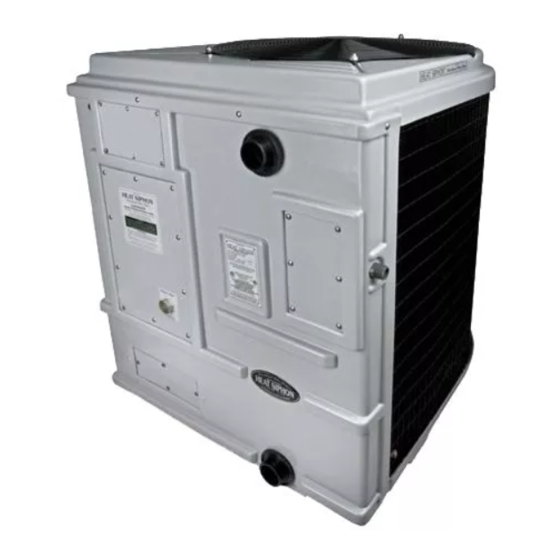
200,375,575 Series Heat Only Models
575HC and 700HP Series Models
For Heat Siphon® Swimming Pool Heat Pumps
All Z & C Series Heat Siphon Models including
220Volt -1 Ph-60 Hz ONLY: C200HP, C250HP, C375HP, C575HP, Z250HP, Z375HP , Z575HP, Z700HP
220Volt -1 Ph-50 Hz ONLY: C200HP50, C250HP50, C375HP50, C575HP50, Z250HP50, Z375HP50 , Z575HP50
220Volt -3 Ph-50/60 Hz: C250HP3, C375HP3, C575HP3, Z250HP3, Z375HP3 , Z575HP3, Z700HP3
380/460 Volt - 3 Phase - 50/60 Hz - C200HPX, C250HPX, C375HPX, C575HPX, Z250HPX, Z375HPX, Z575HPX, Z700HPX
440 Volt - 3 Phase - 60Hz - C575HP4, Z575HP4, Z575HP4, Z700HP4
Copyright 2019 United States ThermoAmp Inc. ALL RIGHTS RESERVED
Publisher: United States ThermoAmp Inc.
1223 Heat Siphon Lane , Latrobe, Pa. 15650
724-537-3500
i

Advertisement

Table of Contents
loading

Summary of Contents for Heat Siphon Z Series

  • Page 1 575HC and 700HP Series Models For Heat Siphon® Swimming Pool Heat Pumps All Z & C Series Heat Siphon Models including 220Volt -1 Ph-60 Hz ONLY: C200HP, C250HP, C375HP, C575HP, Z250HP, Z375HP , Z575HP, Z700HP 220Volt -1 Ph-50 Hz ONLY: C200HP50, C250HP50, C375HP50, C575HP50, Z250HP50, Z375HP50 , Z575HP50...
  • Page 2 But MAKE NO MISTAKE - We have invented, designed and pioneered most of what has become the swimming pool heat pump of today. Heat Siphon® was the first pool heater to use a titanium heat exchanger, the Copeland Scroll compressor and vacuum formed PVC cabinets. We are the only pool heater manufacturer using a patent pending electrically isolated heat exchanger backed by an unconditional lifetime full replacement corrosion warranty.
  • Page 3: Table Of Contents

    6.2 Pool Spa Combo Plumbing . . . . . . . . . . . . . . . . . 28 4.2 Locating Your Heat Siphon® . . . . . . . . . . . . . . . . .7 1 Pump- Heating Pool or Spa .
  • Page 4 HEAT SIPHON Owner/Service Guide ® 6.2 T-SPA - Timed SPA Mode . . . . . . . . . . . . . . . . . . 45 Specifications by Model .
  • Page 5: Owners Section

    Just like a room air conditioner moves 2 to 3 units of heat from your home for every unit of electricity it consumes, Heat Siphon® uses 1 unit of electric energy to move 4 units of heat from the air and thus it provides 5 units of heat to your pool.
  • Page 6: Heat Siphon® Exterior Parts

    Don’t Void Your Warranty! This section contains all the information you will need to ensure that your Heat Siphon® has been properly installed. Read this section before allowing a new dealer to install your unit. If your installer is not an Authorized Heat Siphon®...
  • Page 7: Use A Qualified Installer

    4.2 Locating Your Heat Siphon® As long as you provide plenty of fresh air and give it adequate clearance space all around, Heat Siphon can be installed virtually anywhere outdoors. Unlike gas heaters whose pilot lights can be blown out, Wind has no effect on Heat Siphon®...
  • Page 8: Provide Full Flow - No Bypass

    It won’t rust, fade, chip or peel. If the air temperature drops below about 42°F while the Heat Siphon® is running then any water in the air will begin to freeze and form frost or ice on Heat Siphon’s large horseshoe shaped evaporator fins.
  • Page 9: Pool Heating Considerations

    Heat Siphon® is equipped with a flow sensing switch which turns it on and off automatically when the pool pump is turned on or off. However, you must still run the pool pump long enough each day to allow Heat Siphon®...
  • Page 10: Pool Pump Run Time

    5.2 Pool Pump Run Time Just like other pool heaters, Heat Siphon® can add heat to the pool only when the filter pump is running. So the question is how many hours a day do you run your pool pump- 24, 16, 12 or 8 hours per day? NOTE: In ANY given pool or spa piping system, if you DOUBLE the flow rate, you QUADRUPLE the WATTS needed to pump water thru it.
  • Page 11: Owner Troubleshooting

    6 Owner Troubleshooting The purpose of this section of the manual is to provide some GUIDANCE FOR HEAT SIPHON® OWNERS with little or no technical background who have a problem with their Heat Siphon®.
  • Page 12: Unit Tries To Start Then Does Nothing

    3. Is the pool filter clean and pool water flow stable? A clogged filter or air leak in the pool pump return line can cause erratic water flow and air in the lines which in turn can cause Heat Siphon® to cycle- restore the correct water flow.
  • Page 13: Maintenance & Winterizing

    CAP DUE TO FREEZING. If you have not properly winterized (See next section) this will not be covered under your warranty. Before calling your dealer, here are some tests you should perform: 1. TURN OFF YOUR HEAT SIPHON, KEEP YOUR POOL PUMP ON and wait until basepan empties. If the Water Leak Stops IT IS NORMAL CONDENSATION 2.
  • Page 14: Cleaning

    ELECTRIC SHOCK HAZARD. Heat Siphon’s solid PVC cabinet may be cleaned using any of the automotive vinyl cleaners, or soap and water. An abrasive cleaner or bathtub porcelain cleanser will remove most stubborn stains. Dirt and leaves should be swept from the finned horse shoe shaped evaporator if build up occurs.
  • Page 15: Installer Section

    Black acrylic enamel spray paint can also be used to repair any cosmetic damage. 1.1 Moving & Handling Precautions If only a few simple handling rules are followed, Heat Siphon® can be moved virtually anywhere with no problems: 1. DO NOT DROP OR TAILGATE THE HEAT SIPHON .
  • Page 16: Planning Installation

    3. DO NO LIFT THE HEAT SIPHON® BY ITS TOP / VENTURI - USE HAND HOLES IN BASE. Use a fork truck, roller conveyor or an inclined plane to unload the Heat Siphon® carton. Although the special PVC plastic used in the HEAT SIPHON® cabinet is extremely tough and more than adequate for shipment even in cold weather, it will probably break or crack if dropped from a truck tailgate.
  • Page 17: Physical Location

    In addition, the following guideline should be adhered to when picking the location: 1. Allow 24 to 36 inches of open area all around the Heat Siphon® for good air circulation and service access. Avoid any overhangs or structures which could cause exhaust air to recirculate from the top of the unit back into the sides.
  • Page 18: Distance From The Spa

    C & Z 200, 250,375 & 575 series heating only and cooling only models: Heat Siphon’s exclusive FULL FLOW Titanium heat exchanger has a minimal pressure drop and requires NO SPECIAL PLUMBING arrangement. It should be considered as just another length of PVC pipe in your pool filtration system.
  • Page 19: Electrical Power Required

    UPSTREAM of any electronic chlorinators or chemical pumps. SIZE: All Heat Siphon®’ s have 1.5 “ x 2” fittings for connection to the pool or spa filtration piping which will accept 1.5” schedule 40 PVC pipe directly or 2” SCH 40 PVC pipe with a 2” PVC coupling. The in-line water pressure drop produced by Heat Siphon is less than 1.5 psi at 30 GPM.
  • Page 20: Code Requirements

    Other Approved Raceways .....18 inches 2. UF cable (approved for direct burial ) is permitted for supply runs from the circuit breaker to the Heat Siphon®.
  • Page 21: Gfci Breaker Protection

    The graphic shows proper GFCI Breaker connection to avoid false tripping using a Seimens 50 Amps GFCI breaker. According to Siemens product sheet: In a 220 volt single phase supply circuit to your Heat Siphon there are 3 wires: • 2 HOT wires (both white or black) which come from the two poles of a 220 volt breaker •...
  • Page 22: Electrical Disconnect Switch

    " the subject equipment. This means that if the circuit breaker box which supplies the Heat Siphon® STAINLESS STEEL is not within sight of the Heat Siphon®, you may be required to install a waterproof disconnect switch/box at or FASTENERS COOL AIR near (within sight of ) the installed unit to meet the National Electrical Code.
  • Page 23: Multiple Units

    Indoor installations of Heat Siphon® not only heat the pool, but provide the added benefit of dehumidification of the pool room. When the Heat Siphon® cools down the room air to extract heat out of it, the moisture in the air condenses on the cold evaporator, thus drying the air.
  • Page 24: Spa Heating Issues - See

    Assuming you have picked the best location and orientation and the necessary amperage electrical power supply and bonding circuits are in place, the only work remaining is final wiring and plumbing of the Heat Siphon®. 4.4 Tools / Materials Required The following is a suggested list of tools and materials normally required for Heat Siphon®...
  • Page 25: Optional Recommended Materials

    Heat Siphon®: 1. Installation of PVC unions or hose clamp type flexible couplings at the Heat Siphon® water inlet and outlet lines is recommended to permit easy removal of the front panel if necessary for future service. ALLOW AT LEAST 12 INCHES OF STRAIGHT PIPE IN AND OUT OF THE UNIT BEFORE INSTALLING UNIONS.
  • Page 26: Final Plumbing Into Pool Or Spa

    SIZE: All Heat Siphons have 1.5 “ x 2” fittings for connection to the pool or spa filtration piping. The in-line water pressure drop produced by Heat Siphon is so low (less than 11/2 psi at 30 GPM) that as far as the pool pump is concerned the Heat Siphon®...
  • Page 27: In Floor Cleaning Systems

    HEAT SIPHON Installer Section ® 6.1 In Floor Cleaning Systems Heat Siphon Plumbing Required for In Floor Cleaning Systems PLUMBING KEY AIR FILLED WATER HAMMER WATER FILLED SURGE SUPPRESSOR such as STAND PIPE CAPPED OFF WITH AIR INSIDE 36” MIN...
  • Page 28: Pump- Heating Pool Or Spa

    HEAT SIPHON Installer Section ® 1 Pump- Heating Pool or Spa POOL SPA COMBO One Pump & Filter with Two 3-way Valves Heating & Filtering Spa Only Valves set - from spa to spa Filter HEAT SIPHON Heating & Filtering Pool Only...
  • Page 29: Pump- Spillover Mode

    HEAT SIPHON Installer Section ® 1 Pump- Spillover Mode POOL SPA COMBO One Pump & Filter with Two 3-way Valves Spill Over Mode Valves set - from pool to spa Filter HEAT SIPHON Spill Over Mode Valves set - from pool to pool & spa...
  • Page 30: Pump- Heating Pool Or Spa Only

    HEAT SIPHON Installer Section ® 2 Pump- Heating Pool or Spa Only POOL SPA COMBO Two Pumps & Two Filters with Three 3-way Valves & Four Check Valves Heating & Filtering Pool / Filtering Spa Valves set from pool to heater to pool / from spa to spa...
  • Page 31: Pump- Spillover Mode

    HEAT SIPHON Installer Section ® 2 Pump- Spillover Mode POOL SPA COMBO Two Pumps & Two Filters with Three 3-way Valves & Four Check Valves Spill Over Mode - Pool Pump Only Heating & Filtering Pool & Spa Valves set from pool to spa...
  • Page 32: Initial Start-Up

    LED should turn on SOLID ORANGE signifying that it is waiting for water flow • If your Heat Siphon continues to run when the pump is off the LED will blink GREEN until the overheat switch is tripped. It will then shut off and the LED will blink RED. You must adjust the of flow switch (See section 1.3 below)
  • Page 33: First Startup Of Digital Models

    1. If the pool is BELOW the unit and the Heat Siphon® won’t turn on with the pool pump, turn the pressure switch adjustment thumb wheel to the right until the top of the switch is at the MINIMUM SETTING (1 psi).
  • Page 34: Water Pressure Switch Location

    HEAT SIPHON Installer Section ® Adjusting Water Pressure Switch - Unit Elevated Above Pool IF UNIT IS WELL ABOVE POOL WATER IF UNIT IS WELL ABOVE POOL WATER YOU MAY NEED TO CREATE BACK YOU MAY NEED TO CREATE BACK...
  • Page 35: Digital Player Section

    HEAT SIPHON Digital Player Section ® Digital Player Section This section of this Manual applies to all digital models and specifically details the operation of the Digital Player Controller that is built into all Digital Models including Heating Only, Cooling Only and Heat/Cool Models.
  • Page 36: Led Status Lights

    This is to give the water pump time to push all the bubbles through the system and achieve good water flow before the Heat Siphon turns on. You will see it as, FLO, 14, 13, 12, 11, FLO, 9, 8, 7, 6 etc. Modes: (POOL, SPA, AUTO PIC, OFF) 1.2 LED STATUS Lights...
  • Page 37: Changing Pool Temperature

    No matter what MODE your Player is in, it will not allow your Heat Siphon to run if there are any safety switches tripped or errors. That means there must also be water flow and air above 45°F to 50°F. Switching between any mode is normally not necessary or recommended unless you have a pool/spa combo and are using manual 3 way valves to switch from pool to spa or spill over mode.
  • Page 38: Spa Mode

    3.4 AUTO-PIC Mode AUTO or AUTO-PIC Mode is a way for the Heat Siphon to decide, on its own, what body of water you are heating (pool or spa) and then heat that body of water to the correct set point (pool set point or spa set point). This is a convenience feature and the goal is to allow you to simply turn your pump off, switch your valves to pool or spa, and turn your pump back on.
  • Page 39: Ec Mode (External Control)

    3.5 EC Mode (External Control) If you elect NOT to use Heat Siphon Brand Digital / Wireless Pool/Spa Controller Accessories, using the EC mode, you can still interface your Heat Siphon’s Player Control Board with any other 3rd party pool/spa control systems.
  • Page 40: Test Mode

    Player in the OFF mode using the ”Switching Modes” instructions above. NOTE: In "EC" mode, the thermostat will still turn your Heat Siphon off when its set point is reached. If you do not want to use the built in Thermostat set point you must raise the set point above the 3rd party controller tempera-...
  • Page 41: Changing Max Ec Set Point

    4.2.2 Manual OFF in EC Mode You can turn your Heat Siphon “OFF” manually while it is in EC mode so it will remain off and ignore any 3rd party controller by using the ”Switching Modes” instructions above: 1.
  • Page 42: Locking The Player

    Heating Mode or "tSPA" as it appears on the 7 segment 4 digit LED. S-SPA Menu is designed to limit the amount of time the Heat Siphon will stay in the SPA Mode (heating to the SPA set point), after which Heat Siphon will revert back to the POOL Mode and heat to its set point.
  • Page 43: T-Spa - Timed Spa Mode

    82°F . For example , if the pool set point is 82°F, only a 20°F rise is needed to get to 102°F instead of starting from cold water. In addition, users can't forget to turn off the Heat Siphon when they are done using the spa, since it is always timed to go idle.
  • Page 44: Low Refrigerant Pressure (Lo P)

    SERVICE CODE - ERRORS REQUIRING USER INTERVENTION - These are Service Codes that turn off the Heat Siphon until either the UP or DOWN arrow key is pressed. Then the Player restarts the unit and the error code goes away. This error is counted and stored.
  • Page 45: Low Air Temp. Warning (Lo A)

    ALERT CODE - Heat Siphon is equipped with a refrigeration high pressure switch to detect low water flow. • If the pressure goes above a set value it opens and shuts off the Heat Siphon. This switch will auto-re- set at a slightly lower pressure.
  • Page 46: Low Water Flow (Lo / Flo)

    ALERT CODE - High voltage from the transformer greater than 31.2 VAC to the Player Board for more than 4 seconds will cause this error message to appear • Verify correct power connection to Heat Siphon and the transformer • Voltage surges may cause this temporarily...
  • Page 47: Low Volts (Lo / Uolt)

    This is usually caused by improper power supply installation wiring 7.9 Main Contactor Short (HS S) ALERT CODE - The two wires going from the Player to the Heat Siphon’s 24 volt AC main contactor coil has a short circuit.
  • Page 48: Air Temp Sensor Short (Sa S)

    SERVICE ERROR - No Pod Service Code means the Heat Siphon is looking for an external hardwired add on Pod (See Accessories - J-POD, T-POD, S-POD) and it is shutting the Heat Siphon down because it has been controlling a pump and no longer can detect or control the pump so to be on the safe side it shuts the heater and POD terminals down and waits for user interaction.
  • Page 49: High Air Temperature (Air / Hi)

    7.24 Circuit Board Errors The following are hardware errors detected by the software and most likely require that the Player board be replaced • Board OPEN - Heat Siphon - (Brd1) • Board OPEN - Reversing Valve - (Brd2) • Board OPEN - POD - (Brd3) •...
  • Page 50: Analog Timerstat Pro Section

    1.3 Timerstat Pro Error Codes - Status LED Once power is applied to the Heat Siphon, the LED will tell you a lot of information depending it what color it is and whether or how it is blinking. Here is the basic sequence of lights : •...
  • Page 51 • GREEN BLINKING SLOWLY (2 second) - Heat Siphon ON - Heating Pool • GREEN ON SOLID - Pool is HEATED to set-point & Heat Siphon has turned OFF • RED BLINKING - RPE = Refrigerant Pressure Error (Low or High Pressure) - Causes - Air Below 50°F, Low Flow, Bad Fan Motor - Self correcting unless repeated...
  • Page 52: Analog Model Wiring Diagrams

    Wiring Diagrams Appendix A Analog Model Wiring Diagrams TimerStat Pro 220 volt-1 ph-50/60Hz (2 Pole) 240/ 24v TRANSFORMER Appendix A-52...
  • Page 53: Timerstat Pro 220 Volt-1 Ph-50/60Hz (3 Pole

    Wiring Diagrams TimerStat Pro 220 volt-1 ph-50/60Hz (3 Pole) 240/ 24v TRANSFORMER Appendix A-53...
  • Page 54: Timerstat Pro 220 Volt-3 Ph-60Hz

    Wiring Diagrams TimerStat Pro 220 volt-3 ph-60Hz 240/ 24v TRANSFORMER Appendix A-54...
  • Page 55: Timerstat Pro 380 Volt-3 Ph-50Hz

    Wiring Diagrams TimerStat Pro 380 volt-3 ph-50Hz 240/ 24v TRANSFORMER Appendix A-55...
  • Page 56: Timerstat Pro 440 Volt-3 Ph-60Hz

    Wiring Diagrams TimerStat Pro 440 volt-3 ph-60Hz 440/ 24v TRANSFORMER Appendix A-56...
  • Page 57: Digital Model Wiring Diagrams

    Wiring Diagrams Digital Model Wiring Diagrams Digital 220 volt-1 ph-50/60Hz (2 Pole) 240/ 24v TRANSFORMER Appendix A-57...
  • Page 58: Digital 220 Volt-1 Ph-50/60Hz-(3 Pole

    Wiring Diagrams Digital 220 volt-1 ph-50/60Hz-(3 Pole) 208/220v/24v TRANSFORMER Appendix A-58...
  • Page 59: Digital 220 Volt-3 Ph-60Hz

    Wiring Diagrams Digital 220 volt-3 ph-60Hz 208/220v/24v TRANSFORMER Appendix A-59...
  • Page 60: Digital 380 Volt-3 Ph-50Hz

    Wiring Diagrams Digital 380 volt-3 ph-50Hz 240/ 24v TRANSFORMER Appendix A-60...
  • Page 61: Digital 440 Volt-3 Ph-60Hz

    Wiring Diagrams Digital 440 volt-3 ph-60Hz 240/ 24v TRANSFORMER Appendix A-61...
  • Page 62: Specifications By Model

    Specification by Model Appendix B Specifications by Model Heat Siphon Compressor Mfr Power Supply Req'd @60 Hz @50 Hz Wire Breaker Lbs Model No. Model Number Voltage HZ PH BTUh-COP BTUh-COP Cap. MCA Amps R410A LRA Classic "C" Series (TimerStat Pro Equipped)
  • Page 63: Classic "Cf" Flow Sensing Series

    Specification by Model Heat Siphon Compressor Mfr Power Supply Req'd @60 Hz @50 Hz Wire Breaker Lbs Model No. Model Number Voltage HZ PH BTUh-COP BTUh-COP Cap. MCA Amps R410A LRA Z575HP3 ZP72KCE-TF5 208-230 60 3 120.8K - 6.20 NA - NA 34.5 40 6.75 164...
  • Page 64 Specification by Model Heat Siphon Compressor Mfr Power Supply Req'd @60 Hz @50 Hz Wire Breaker Lbs Model No. Model Number Voltage HZ PH BTUh-COP BTUh-COP Cap. MCA Amps R410A LRA ZF200HP50 ZP25K5E-PFJ 220-240 50 1 NA - NA 37K - 5.6 40/370 16.1 25 3.10 60...
  • Page 65: Accessories Available

    A daughter board plug in which provides screw down connections for pool spa combo owners so they can use 3rd party controllers to switch between Heat Siphons pool and spa set points as well as turning Heat Siphon on and off 1.1.2 EasyClock...
  • Page 66: Wireless Add-Ons

    The Wireless Heat Siphon Coach® System is an FCC approved wireless commercial swimming pool controller designed to work with all Digital Heat Siphon® Swimming Pool Heat Pumps. It monitors and controls all Heat Siphons in the system while providing load management and reporting the operating status to the pool manager on the Heat Siphon Coach®...
  • Page 67: Spa / Hot Tub Heating Issues

    SPA / HOT TUB Heating Issues Appendix D SPA / HOT TUB Heating Issues WARNING! Water Temperature Safety Failure to heed the following may result in permanent injury or death. Prolonged immersion in water warmer than normal body tempera- ture may cause a condition known as HYPERTHERMIA. The symp- toms of hyperthermia include: unawareness of impending hazard, failure to perceive heat, failure to recognize the need to exit the spa, and unconsciousness.
  • Page 68: Thermostat Set Point Depression

    Spa or Hot Tub. Most Spas which are heated separately or as "stand alone" spas using a Heat Siphon or other Spa Heaters especially fossil fuel types tend to be located out of sight of the spa to prevent bathers from tampering with the thermostat as well as to keep the public away from hot surfaces and fumes.
  • Page 69 SPA / HOT TUB Heating Issues Spa/Hot Tub Thermostat Setpoint Depression SPA Inlet °F = Heater Outlet °F - Ground Heat Loss SPA °F = Mixed SPA °F (Inlet + Main Spa Bulk Water) Heater Inlet °F + ° F Rise = Heater Outlet °F Average of Skimmer + Main Drain Heater Thermostat BURIED PIPING = GROUND HEAT LOSS...
  • Page 70: Spa Temperature Sensor Calibration

    As of Player software revision 1.253 (heating only models) and 1.309 (Heat/Cool models) Heat Siphon's DIGITAL Z series Player Controller provides a way to calibrate the spa temperature sensor by increasing the inlet tempera- ture reading to match the actual spa temperature. The temperature may be increased from 1 to 5°F in 1°F steps.
  • Page 71: Spa Thermostat Set Points Above 102°F

    Based on CPSC Guidelines it appears unnecessary or at least unwise to heat above 102°F,. and even though the UL standard for spa heaters allows a maximum thermostat set point of 104°F , Heat Siphon has chosen to set the default maximum spa set point temperature of 102°F.

Table of Contents