
Related Manuals for Dynapac Svedala Demag DF 115 P/D


Summary of Contents for Dynapac Svedala Demag DF 115 P/D
- Page 1 OPERATION & MAINTENANCE Paver finisher Svedala Demag DF 115 P/D DF 125 P/D Typ 34 Keep this manual for future reference Order number for this manual: D900981408 02-0107 ......
- Page 2 VALUE QUALITY THE ORIGINAL Your Authorized Dynapac Dealer:...
-
Page 3: Table Of Contents
Table of contents Preface ..................1 General safety instructions ................ 2 Acts, directives, accident prevention regulations ........2 Warning instructions .................. 2 Prohibitive signs ..................4 Protective gear ................... 5 Environmental protection ................6 Fire prevention ................... 6 Further instructions ..................7 Correct use and application ........... - Page 4 EN standards ................... 21 Continuous sound level DF115P/D, Deutz TCD2013L04 ......21 Operating conditions during measurement ..........21 Measuring point configuration ..............21 Continuous sound level DF125P/D, Deutz TCD2013L06 ......22 Operating conditions during measurement ..........22 Measuring point configuration ..............22 Vibration acting on the entire body ............
- Page 5 D3.0 Operation ................. 1 Operating elements on the paver finisher ..........1 Batteries (71) ..................1 Battery main switch (72) ................ 1 Transport safeguards for the hopper (73) ..........2 Mechanical screed transport safeguard (to the left and the right beneath the driver’s seat) (74) ......3 Seat lock (behind the driver’s seat) (75) ..........
- Page 6 D4.5 Operation ................. 1 Preparation of operation ................1 Required devices and aids ..............1 Before starting work (in the morning or when starting paving) ....1 Checklist for the machine operator ............2 Starting the paver finisher ................4 Before starting the paver finisher ............
- Page 7 Set-up and modification ............1 Special notes on safety ................1 Auger ......................2 Height adjustment ..................2 Auger crossbeam installed in a fixed position ..........2 Mechanical adjustment with ratchet (optional) ........... 3 In case of hydraulic adjustment (option) ............ 3 Auger extension, auger type I ..............
- Page 8 F5.1 Maintenance - Engine ............. 1 Maintenance - engine sub-unit ..............1 Maintenance intervals ................2 Points of maintenance ................4 Engine fuel tank (1) ................4 Engine lube-oil system (2) ..............5 Engine fuel system (3) ................7 Engine air filter (4) ................. 9 Coolant system of the engine (5) ............
- Page 9 F8.0 Maintenance - Electronic System .......... 1 Maintenance - Electronic System .............. 1 Maintenance intervals ................2 Points of maintenance ................5 Batteries (1) ................... 5 Generator (2) ..................6 Adjustment of belt tightness ..............8 Replacement of belt ................9 Electric fuses (3) ..................
-
Page 11: Preface
In the interest of continued development, the manufacturer reserves the right to make changes to the machine (which will not, however, change the essential features of the type of machine described) without updating the present operating instructions at the same time. Dynapac GmbH Wardenburg Ammerländer Strasse 93 D-26203 Wardenburg / Germany... -
Page 12: General Safety Instructions
The following alerts, prohibitions and instructions refer to the risks to which people, machinery and environment are exposed. Ignoring these instructions, bans and commands may lead to fatal injuries! Furthermore, the Dynapac publication "Directives for the correct and specified appli- cation of pavers" shall also be observed. Warning instructions... - Page 13 Attention: risk of hand injury! Attention: hot surfaces or hot liquids! Warning, risk of falling off! Attention: hazardous batteries! Attention: materials harmful to health and irritating substances! Attention: flammable materials! Attention: gas bottles!
-
Page 14: Prohibitive Signs
Do not sprinkle with water! Do not extinguish with water! Do-it-yourself maintenance is prohibited! Maintenance can be performed by skilled professionals only! Contact the Dynapac service! Danger of fire: do not use open flame and no smoking! Do not turn on! -
Page 15: Protective Gear
Protective gear The applicable local regulations may define the use of different protective gear! Observe these specifications! Protect your eyes with googles! Wear appropriate head protection! Protect your hearing with appropriate ear mufflers! Protect your feet with safety footwear! Always wear tight, conforming working coveralls! Wear visibility vest for good visibility! In case of polluted air, wear respiratory mask! -
Page 16: Environmental Protection
Environmental protection The locally applicable acts, directives and waste disposal regulations shall be ob- served, even if the attention is not specifically directed to these. During cleaning, maintenance and repair operation the materials polluting water e.g.: - lubricants (oils, grease) - hydraulic oil - gas oil - coolant... -
Page 17: Further Instructions
Further instructions Observe the manufacturer's and other instructions! e.g. the maintenance instructions of the engine manufacturer Description / figure in case of an electrically heated design! Description / figure in case of an electrically heated design! -
Page 19: A Correct Use And Application
The “Guidelines for the Correct Use and Application of Paver finishers” compiled by Dynapac are included in the scope of delivery for the present machine. The guide- lines are part of the present operating instructions and must always be heeded. Na- tional regulations are fully applicable. -
Page 21: B Vehicle Description
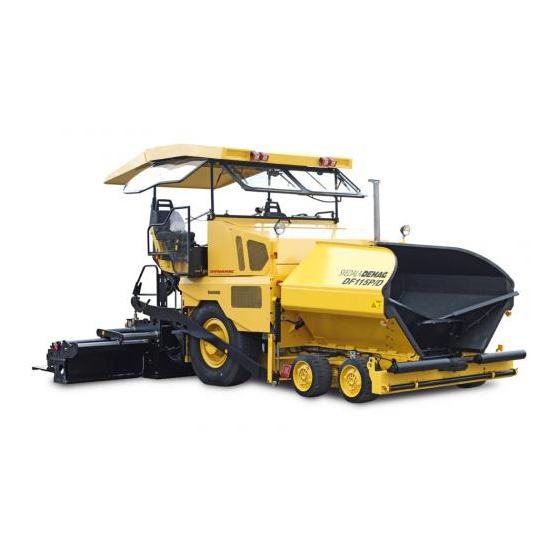
B Vehicle description Application The Svedala Demag DF115P/D / DF125P/D is a rubber tyre fitted paver finisher that is used for laying bituminous mixed material, roll-down or lean-mixed concrete, track- laying ballast and unbound mineral aggregates for foundations for paving. 64_ISO_DEM.bmp... -
Page 22: Description Of Assemblies And Functions
Description of assemblies and functions 634_EM_ISO.bmp Item Designation Material compartment (hopper) Truck push rollers Tube for sensor rod (direction indicator) and holder for levelling shoe Rear wheels Levelling cylinder for paving thickness Traction roller Traction arm rail Paving thickness indicator Machine drive Auger Screed... -
Page 23: Vehicle
Vehicle Construction The paver finisher has a welded steel frame on which the individual components are mounted. The large drive wheels together with the front tandem shaft jointly compensate the irregularities of the soil and as a result of the suspension of the screed they guarantee a particularly high paving precision. - Page 24 Hydraulic system: The diesel engine drives the hydraulic pumps for all main drives of the paver finisher via the attached distribution gear and its auxiliary drive shafts. Traction drive: The continuously adjustable traction drive pumps are connected to the traction motors by means of high pressure hydraulic hoses. These hydro-motors can drive the drive wheels through a planetary gear.
- Page 25 Height adjustment and extension of augers: Height adjustment and extension of augers ensure optimum adaptation to a wide range of paving thicknesses and widths. The basic configuration allows the height to be adjusted by attaching chains to the side arms and by actuating the hydraulic screed lifting device. When using ratchets for height adjustment (option), barrel nuts at the guide supports in the rear wall are used to adjust the height.
-
Page 26: Danger Zones
Danger zones In these areas of the machine there is a danger of pulling in or crushing due to the rotating, transporting or moving parts! -
Page 27: Safety Devices
Safety devices Safe operation is only possible when all operating and control elements are function- ing correctly and when all safety devices are in position. Check the function of these devices at regular intervals. (see chapter D, section 2.1). Emergency stop button - on the operating panel - on the two remote control units F0005_A1.EPS... -
Page 28: Main Switch (17)
Main switch (17) Mainswitch.tif/Mainswitch_SK.eps Hopper transport safeguards (18) Hopperlock2.tif/Hopperlock_SK.eps Screed transport safeguards (19) F0083_A1.TIF Latch for protective roof (20) F121Cb.Tif... - Page 29 634_side_DEM.bmp/Feuerlöscher.bmp Item Designation 25 Fire fighting device 26 Engine hood 27 Lateral flaps 28 Walkway 29 Screed coverings 30 Hazard warning lights of the screed 31 Auger covers Accessories: - Wedges - Warning triangle - First-aid kit...
-
Page 30: Technical Data, Standard Configuration
Technical data, standard configuration Dimensions (all dimensions in mm) 1962 2020 6500* 2070 2550 3388 *EB51 634_side_DEM.bmp,634_front_DEM.bmp For the technical data of the screed, see the operating instructions of the screed. B 10... -
Page 31: Allowed Angle Of Rise And Slope
Allowed angle of rise and slope max 15° max 15° max 15° 634_side_DEM.bmp,634_front_DEM.bmp Before operating your machine in an inclined position (gradient, slope, lateral inclina- tion) which is above the specified limit value, please, consult with the customer serv- ice for your machine! Allowed angle of driving up max 14°... -
Page 32: Weights Df115P/D (All Weights In T)
Weights DF115P/D (all weights in t) Type DF115P/D Paver finisher without screed about 14,6 Paver finisher with screed: - EB 51 about 16,5 Including mounted accessories for max. paving about 0,9 width plus max. With filled hopper additionally max. about 12,5 max. -
Page 33: Performance Data Df115P/D
Performance data DF115P/D EB 51 2,55 2,00 5,10 7,30* EB 51+ 2,55 2,00 5,10 *The maximum working width depends on the paving conditions! Travelling speed 0 - 19,5 km/h Transport speed - reversing 0 - 6 km/h Working speed 0 - 29,0 m/min Layer thickness 0 - 300... -
Page 34: Performance Data Df125P/D
Performance data DF125P/D EB 51 2,55 2,00 5,10 8,10* EB 51+ 2,55 2,00 5,10 *The maximum working width depends on the paving conditions! Travelling speed 0 - 19,5 km/h Transport speed - reversing 0 - 6 km/h Working speed 0 - 29,0 m/min Layer thickness 0 - 300... -
Page 35: Traction Drive/Chassis
Traction drive/chassis Continuously variable hydrostatic drive, with Drive pump and engine Transmission Planetary gear Speeds (see above) 2 x 14.00 R-25 (air filled tyres) (water filled tyres Drive wheels Steering wheels 4 x 560 / 390 - 300 (elastic solid rubber tyres) 2 / 4 wheel hub hydro-motor, freely selected, vari- Front wheel drive able drive performance,... -
Page 36: Material Compartment (Hopper)
5.13 Material compartment (hopper) Volume about 6.0 m = about 13.0 t Minimum inlet height, center 520 mm Minimum inlet height, outside 600 mm 5.14 Material conveying Conveyors Left and right side separately controllable Drive Hydrostatic, continuously controllable Conveying volume controller Fully automatic via configurable switching points 5.15 Material distribution... -
Page 37: Screed Lifting Device
5.16 Screed lifting device At standstill: - Screed stop - Screed stop with pretensioning (max. pressure 40 bar) Special functions During paving: - Screed charging - Screed relieving (max. pressure 40 bar) Mechanical grade control, Levelling system optional systems with and without slope control 5.17 Electrical system... -
Page 38: Location Of Instruction Labels And Identification Plates
Location of instruction labels and identification plates B 18... - Page 39 Denomination Label ”Filler neck for diesel fuel” * Label ”Filler neck for engine oil” * Label „Heed the operating instructions!“ Warning label ”Danger of squeezing!” ** Punched vehicle identification number Label ”Securing or fixing points for crane transportation”** Paver finisher identification label „CE + noise level“...
-
Page 40: Identification Label For The Paver Finisher (6)
Identification label for the paver finisher (6) Fertiger3.tif Denomination Type of paver finisher Year of manufacture Serial number of the paver finisher series Max. permissible operating weight, incl. all attachments, in kg Max. permissible load on the front axle, in kg Max. -
Page 41: En Standards
EN standards Continuous sound level DF115P/D, Deutz TCD2013L04 The operator always must use ear protection. The imission value at the ear of the driv- er varies depending on the materials used for paving and may even rise above 85 dB (A). -
Page 42: Continuous Sound Level Df125P/D, Deutz Tcd2013L06
Continuous sound level DF125P/D, Deutz TCD2013L06 The operator always must use ear protection. The imission value at the ear of the driv- er varies depending on the materials used for paving and may even rise above 85 dB (A). If no ear protection devices are used, hearing can be impaired. The noise emission level of the paver finisher was measured under free-field condi- tions according to EN 500-6 draft, dated March, 1997, and ISO 4872. -
Page 43: Vibration Acting On The Entire Body
Vibration acting on the entire body When the machine is used properly, the weighted effective acceleration values at the driver’s seat of a = 0.5 m/s according to prEN 1032-1995 draft are not exceeded. Vibrations acting on hands and arms When the machine is used properly, the weighted effective acceleration values at the driver’s seat of a = 2.5 m/s... -
Page 45: C1.0 Transportation
C 1.0 Transportation Safety regulations for transportation Accidents can happen when the paver finisher and the screed are not properly pre- pared for transportation or when transportation is carried out improperly! Reduce both the paver finisher and the screed to their basic widths. Remove all pro- truding parts (such as the levelling device, auger limit switches, aprons, etc.). -
Page 46: Transportation On Low-Bed Trailers
Transportation on low-bed trailers Reduce the paver finisher and the screed to their basic widths; also remove any at- tached side plates. The maximum drive-on angle is included in Chapter „Technical Specifications“! Preparations - Prepare the paver finisher for transportation (see chapter D). - Remove all protruding or loose parts from the paver finisher and the screed (see also the operating instructions of the screed). - Page 47 Operation Switch Buttons Disabling the interlocking of oper- ation Close the hopper halves. Engage both hopper transport safeguards. Lift the screed. Insert the transportation safe- guards of the hopper! Turn the preselecting regulator to zero. Move the drive lever forward. The levelling cylinders are completely extended.
-
Page 48: Drive Onto The Low-Bed Trailer
Drive onto the low-bed trailer Make sure that there are no persons in the danger area during loading. 634_side3_Dyn.bmp - Use the work gear and low engine speed to drive onto the low-bed trailer. - Lower the screed onto wooden blocks on the low-bed trailer. - Switch off the paver finisher. -
Page 49: Secure The Paver Finisher In Its Position To The Low-Bed Trailer
Secure the paver finisher in its position to the low-bed trailer: - Use only proper and permitted load fastening devices. - Use the four securing points provided (1, 2). Depending on the equipment of the machine there can be further support points (3) on the auger frame (3). -
Page 50: Transportation
Transportation Reduce the paver finisher and the screed to their basic widths; also remove any at- tached side plates. Preparations - Prepare the paver finisher for transportation (see chapter D). - Remove all protruding or loose parts from the paver finisher and the screed (see also the operating instructions of the screed). - Page 51 Operation Switch Buttons Disabling the interlocking of operation Close the hopper halves. Engage both hopper transport safe- guards. Lift the screed. Insert the transportation safeguards of the screed. Turn the preselecting regulator to ze- Move the drive lever forward. The levelling cylinder are in fully extended position.
-
Page 52: Traction Drive
Traction drive: Warning Marking Marking Set the Fast/Slow switch to „Hare“. Turn the preselecting regulator to maximum. Use the drive lever to regulate the speed. Risk of accident! - In tight curves avoid sudden steering movements. Moving the steered wheels to locking position requires about 2.5 - 3 full steering wheel turns. -
Page 53: Loading By Crane
Loading by crane Use only lifting gear that can bear the load. (See Chapter B for weights and dimensions). 634_side3_Dyn.bmp/634_front2.bmp Four lifting eyes (1.2) are provided for loading the vehicle with a crane. - Park the paver finisher and render it safe. - Engage the transport safeguards. -
Page 54: Towing
Towing Heed all regulations and apply all safety measures applicable for towing heavy con- struction machines. The towing vehicle must be capable of securing the paver, even on slopes. Use only approved tow bars! If necessary, remove any attachments and accessories from the paver finisher and the screed until the basic width has been attained. - Page 55 Following towing, unscrew the threaded dowel (3) a few turns again and lock with the lock nut (2). The high pressure cartridges (1) have to be fully screwed back in to make the ma- chine usable again. The brakes of the traction drive are now active again and the machine is secured against accidental rolling away.
-
Page 56: Safely Parking The Vehicle
Safely parking the vehicle When the equipment is parked at a loca- tion accessible to the public, it must be secured in such a way that unauthorized persons or playing children cannot dam- age the vehicle. - Pull off the ignition key and the main switch (1) and take it with you –... -
Page 57: D1.3 Operation
D 1.3 Operation Safety regulations Starting the engine, the traction drive, the conveyor, the auger, the screed or the lifting devices can cause injuries or even the death of persons. Make sure before starting any of these devices that no-one is working at, in or be- neath the paver finisher or within its danger area! - Do not start the engine or do not actuate any controls when this is expressly forbid- den! -
Page 58: Operating Elements
Operating elements Operating panel Bedienpult_konv_Rad_634_2.bmp/Element3_konv_Rad_634.bmp/Element1_konv_Kette_635.bmp/Element2_konv_Rad_634.bmp D 1.3 2... - Page 59 Item Designation Brief description Steering is transmitted to the front wheels hydraulically. When travelling in tight curves, take care of the special Steering steering ratio (about 3 turns for changing between steering locks) Risk of accident! For securing the movable operating panel against inadvertent movement at the desired paver finisher height.
- Page 60 Element2_konv_Rad_634.bmp D 1.3 4...
- Page 61 Item Designation Brief description Starting is only possible when the drive lever is in the neutral Starter position. All emergency stop buttons (on the operating panel and the remote controls) must be pulled up. Hare: Travelling speed Tortoise: Working speed for laying When the working speed is selected, the differential Machine drive lock is automatically engaged!
- Page 62 Element2_konv_Rad_634.bmp D 1.3 6...
- Page 63 Item Designation Brief description Key inserted: Ignition on Key pulled out: Ignition, engine off. Key positions: 0 Lights switched off 1 Parking lights / rear lights, instrument panel light, Ignition switch and working floodlight as applicable lighting switch 2 Driving lights 3 Headlights Override the interlocking between 1 and 2 by depress- ing them.
- Page 64 Element1_konv_Kette_635.bmp D 1.3 8...
- Page 65 Item Designation Brief description The transport direction of the conveyor, applicable separately to both sides of the conveyor, can be switched to the opposite direction so that over a short distance it retracts the material directly before the auger. In this way the loss of material can Reverse selection be avoided during transport.
- Page 66 Element1_konv_Kette_635.bmp D 1.3 10...
- Page 67 Item Designation Brief description A Lift the screed. Screed position B Lock the screed (the position appropriate for inserting the transportation safeguard of the screed) C: Lower the screed and set it to „Floating position“ During paving, the screed must always be in the float- ing position.
- Page 68 Element1_konv_Kette_635.bmp D 1.3 12...
- Page 69 Item Designation Brief description It sets the delay time of the prestressed start of the screed. Preselecting regu- The delay time must be set depending on the working lator „Pressure speed. load delay time to start paving“ - High working speed - short delay time - Low working speed - longer delay time A auto: with the drive lever turned on and using the ma-...
- Page 70 l m nt3 konv ad 634 bmp uchtmodul 635 bmp D 1.3 14...
- Page 71 Item Designation Brief description With this the levelling cylinders can be controlled manually, if Levelling cylinder the levelling automatic system is switched off. on the right/left For this, the switch on the remote control shall be in „manual“ sides position. Continuously variable adjustment of speed (in case of moving the drive lever).
- Page 72 Element3_konv_Rad_634.bmp/Leuchtmodul_KONV_Kette_635.bmp D 1.3 16...
- Page 73 Item Designation Brief description Normal display up to 85 °C = 185 °F. Hydraulic oil ther- In case of higher temperature stop the machine, (set mometer drive lever to neutral position), and let the engine cool at idling speed. Find the cause and eliminate the fault. This light is on, if the water separator of the fuel system has established a too high water level.
- Page 74 Element3_konv_Rad_634.bmp/Leuchtmodul_KONV_Kette_635.bmp D 1.3 18...
- Page 75 Item Designation Brief description It must go out soon after start-up. Consider the time of warm- ing up. The hydraulic oil may be too cold and rigid. Oil pressure indica- If the light does not go dark, do not turn on the trac- tor for the hydraulic tion drive.
- Page 76 Element3_konv_Rad_634.bmp/Leuchtmodul_KONV_Kette_635.bmp D 1.3 20...
-
Page 77: Remote Control
Remote control Remote_konv_neu1.bmp With the help of the two remote controls - on the RH and LH sides of the screed - the functions available on the specific side of the paver can be controlled. D 1.3 21... -
Page 78: Front Side
Front side Item Designation Brief description Its function and use are similar to those of the emergency Emergency stop stop button on the operating panel (14). button (o) It is important in such dangerous situations, which cannot be observed by the driver. Horn Its function is similar to the button (7) on the control panel. -
Page 79: Reverse Side
Reverse side Remote_konv_neu1.bmp Item Designation Brief description Connection to the levelling automatic Connect the cable for the grade control unit here. system Connection to the end position switch of Connect the cable for the material limit switch here. the auger Cable for the remote Connect to the socket on the screed control... - Page 80 D 1.3 24...
-
Page 81: D3.0 Operation
D 3.0 Operation Operating elements on the paver finisher Batteries (71) The batteries of the 24 V system are lo- cated under the left maintenance flap. For the specifications, refer to chapter B, ”Technical Data”. For servicing, see chapter F. Heed the instructions when starting the paver finisher externally. -
Page 82: Transport Safeguards For The Hopper (73)
Transport safeguards for the hopper (73) Before parking or transporting the paver finisher, the hopper halves must be swung upwards and the transport safe- guards for the hopper must be inserted. Item: - (a) - outside on the two half-hoppers - (b) - in the feeding hopper (o) Do not enter the hopper while the engine is running! Danger of being caught by... -
Page 83: Mechanical Screed Transport Safeguard (To The Left And The Right Beneath The Driver's Seat) (74)
Mechanical screed transport safe- guard (to the left and the right be- neath the driver’s seat) (74) Used to protect the lifted screed from in- advertent lowering. The screed transport safeguard must be inserted before trans- portation and when work is finished. Transportation with unsecured... -
Page 84: Service Brake („Foot Brake") (76)
Service brake („foot brake“) (76) There is a brake pedal before each driv- er's seat on the LH and RH sides. The service brake acts within the ma- chine drive. Upon operating the brake, the machine drive is regulated to stop automatically (regardless of the position of the drive le- ver). -
Page 85: Separator Fluid Spraying System (80) (O)
Separator fluid spraying system (80) Used to spray the parts coming into con- tact with asphalt with a separator emul- sion. - The indicator lamp (A) lights up when the emulsion pump is running - On/off switch (B) for the emulsion pump - Quick-release coupling (C) for hose connection... -
Page 86: On / Off Switch For Additional Headlight In The Roof (85)
Further switch options for optional equipment features may be located on the central panel: on / off switch for additional headlight in the roof (85): Actuate switch (a) to activate. On / off switch for fuel tank filler pump (85a) If the pump is actuated with the switch (a), the indicator lamp (b) lights up. -
Page 87: On/Off Switch Of Work Headlights (85D)
On/Off switch of work headlights (85d): Actuate switch (a) to switch on. In the switch position „ON“ the control light (b) is on. On/Off switch of flasher (85e): Actuate switch (a) to switch on. In the switch position „ON“ the control light (b) is on. If optionally available 230 V systems are installed, an additional switch cabinet is mounted on the paver finisher:... -
Page 88: Hydraulic Folding Roof (87) (O)
Hydraulic folding roof (87) (o) The hydraulically folding roof is secured by means of a latch (A) at the rear sus- pension on the left and right sides of the machine. This must be released prior to lowering and raising. Once it has reached its terminal position, the roof must be secured with the latch again. -
Page 89: Electric Setting Of The Transportation Volume Of The Conveyor (O) (88)
Electric setting of the transportation volume of the conveyor (o) (88) With this the transport volume of the conveyor can be adjusted when me- chanical limit switch or ultrasonic sensor is used. - The „0“ position of the scale corre- sponds to the smallest adjustable vol- ume. -
Page 90: Ultrasonic Auger Limit Switches (90) (Left And Right)
Ultrasonic auger limit switches (90) (left and right) The limit switches control the material flow at the respective auger half. The ultrasonic sensor is mounted by means of an appropriate leverage to the side plate. Loose clamping lever for ad- justment and modify angle / height of the sensor. -
Page 91: Pressure Control Valve For Screed Charging/Relieving (93)
Pressure control valve for screed charging/relieving (93) Used to adjust the pressure for addition- al charging/relieving of the screed. - See ”screed charging/relieving de- vice”. (Chapters „Operating Panel“, „Opera- tion“). - Pressure display: see pressure gauge (93b). Pressure control valve for screed stop with pretensioning (93a) This valve is located beneath the right- hand bottom flap of the operator´s plat-... -
Page 92: Front Wheel Drive Pressure Regulating Valve (94) (O)
Front wheel drive pressure regulating valve (94) (o) The drive pressure of the supplementary front wheel drive can be adjusted here. F0105_A1.TIF - Engage the front wheel drive with the switch (30). - Pressure display: see pressure gauge (94a). Adjust the pressure on the moving paver so that the driven front wheels do not spin. Pressure gauge of the front wheel drive (94a) (o) It shows the drive pressure of the sup-... -
Page 93: Central Lubrication Unit (O) (100)
Central lubrication unit (o) (100) The central lubrication unit turns on in automatic mode when the drive engine starts. - Pumping time: 12 min - Duration of the break: 2 h It is prohibited to change the factory-set durations of pumping and break without consulting the technical customer serv- ice! Changing the duration of lubrication and... -
Page 94: Particle Filter - Control Light (102) (O)
Particle filter - control light (102) (o) The control light of the particle filter is found under the control track of the oper- ating panel. When observing the control light (a) it is essential: Partikellight.tif Indicator Operating condition Cause / action colour No counterpressure Check the yellow... -
Page 95: Front And Side Window (O) (103)
Front and side window (o) (103) The front window can be folded up for the maintenance works performed at the tank. - Fold the front window by its handle (A) and lock it on the RH and LH sides with the two locks (B) in the upper po- sition. -
Page 96: Adjustment Of Screed Eccentric (O) (104)
Adjustment of screed eccentric (o) (104) To pave thicker layers of material, if the piston rods in the levelling cylinder are operating close to their limit position and if the desired paving thickness cannot be reached, it is possible to alter the ap- proach angle of the screen by adjusting the eccentric. -
Page 97: D4.5 Operation
D 4.5 Operation Preparation of operation Required devices and aids To avoid delays on site, check before starting work whether or not the following de- vices and aids are present: - Wheel loader for transporting heavy extendable parts - Diesel fuel - Engine oil and hydraulic oil, lubricants - Separating agents (emulsion) and manual injector - Two filled propane gas bottles... -
Page 98: Checklist For The Machine Operator
Checklist for the machine operator Check! How? Emergency stop button Push in the button. - on the operating panel The diesel engine and all running drives - on both remote control units o must stop immediately. The paver finisher must immediately fol- Steering low every steering wheel movement in a precise manner. - Page 99 Check! How? For larger working widths, the walkway Auger covers plates must be extended and the auger tunnels must be covered. For larger working widths, the walkway plates must be extended. Hinged walkway plates must be swung Screed covers and walkways down.
-
Page 100: Starting The Paver Finisher
Starting the paver finisher Before starting the paver finisher Before starting the diesel engine and be- ginning operation, the following steps must be performed: - Daily maintenance of the paver finish- er (see chapter F) Check the operating hour counter to de- termine whether or not additional main- tenance work (such as monthly or yearly maintenance) must be performed. -
Page 101: External Starting (Starting Aid)
External starting (starting aid) The engine can be started with the help of an external power source if the batteries are empty and the starter no longer turns. Suitable power sources are: - Other vehicles with a 24 V system - Additional 24 V battery - Start device that is suitable for external starting (24 V/90 A). -
Page 102: After Starting
After starting To increase the engine speed: - Set the RPM regulator (1) to medium speed. - Switch the drive lever (2) to position 1 (slightly moving it from the central po- sition). Let the paver finisher warm up for ca. 5 minutes if the engine is cold. - Page 103 When the hydraulic oil is cold: - Set the switch (3) of the conveyor to „manual“ and the switch (4) of the au- ger to „manual“ (arrow) position. - Set the speed regulator (5) to medium RPM and move the drive lever (6), un- til the conveyor belt and the auger start operating.
-
Page 104: Preparations For Paving
Preparations for paving Separating agent Spray the parts coming into contact with asphalt (hopper, screed, auger, push roller) with a separator emulsion. Do not use diesel fuel as it dissolves the bitumen (prohibited in Germany!). F0147_A1.TIF Screed heater Switch on the screed heater ca. 15–30 minutes (depending on the ambient tempera- ture) before paving begins. -
Page 105: Loading/Distributing Material
Loading/distributing material - Open the hopper with switch (1). Provide guidance for the truck driver when tipping the material mix. - Set the switch (2) of the auger and the switch (3) of the feeder to „auto“ posi- tion. - Set the appropriate auger switch on the remote control and conveyor switch (if applicable) to "auto"... - Page 106 - Switch the conveyors on. The limit switches for the conveyors (89) or (89ao) must switch off when the material has reached the area be- neath the auger crossbeam. - Check that the material is conveyed properly. Manually switch on or off the conveyor if the material is not conveyed properly until a sufficient amount of material lies in front of the screed.
-
Page 107: Starting For Paving
Starting for paving Element2_konv_Kette_635.bmp/Element1_konv_Kette_635.bmp/Tamprev.cdr/Vibrev.cdr/Remote_konv_neu1.bmp D 4.5 11... - Page 108 Set the switches, levers and controls listed below to the specified positions when the screed has reached its operating temperature and a sufficient amount of material lies in front of the screed: Item Switch Position Machine movement fast/slow slow („tortoise“) Preselector regulator On / Off On (at the bottom) Engine RPM (o)
-
Page 109: Checks During Paving
Checks during paving The following points must be constantly observed during paving: Paver function - Screed heater - Tamper and vibration - Engine oil and hydraulic oil temperature - The screed parts must be retracted and extended in time when obstacles are in the - Uniform material transport and distribution or supply to the screed;... -
Page 110: Paving With Functions "Screed Control, Stopping Of Paver Finisher" And "Screed Loading / Unloading
Paving with functions "screed control, stopping of paver finisher" and "screed loading / unloading" General The screed hydraulics can be influenced in two ways to attain optimum paving re- sults: - Screed stop with and without pretensioning with the paver finisher halted, - Screed charging or relieving with the paver finisher driving. -
Page 111: Screed Charging/Relieving
Screed charging/relieving This function charges or relieves the screed regardless of its own dead weight. Switch (1) has the following positions: A: Relieving (screed ‘lighter’) B: Function Off C: Charging (screed ‘heavier’) Screedswitch_all.bmp Switch positions „Screed charging/relieving” are only effective when the paver finish- er moves. -
Page 112: Screed Control With The Paver Finisher At Standstill - With Floating Position Prestressing
Screed control with the paver finisher at standstill - with floating position pre- stressing Similarly to the screed charging and relieving function, a pressure between 2 and 50 bars can be generated with the lifting cylinders of the screed. This pressure acts against the mass of the screed to prevent its sinking into the freshly laid mixture. -
Page 113: Adjustment Of Pressure For The Loading/Offloading Of The Screed
Adjustment of pressure for the loading/offloading of the screed - Move the drive lever from central posi- tion to the third position. - Set the switch (3) to position A (of- floading) or C (loading). - Set thepressure with the regulating valve (93b) and read it on the pres- sure gauge (93c). -
Page 114: Interrupting/Terminating Operation
Interrupting/terminating operation During breaks (e.g. the material supply truck is late) - Determine the approximate duration. - When cooling down of the material be- low the minimum paving temperature must be expected, run the paver fin- isher finisher empty and create an edge like the end of a layer. -
Page 115: When Work Is Finished
When work is finished - Run the paver finisher empty and stop - Lift the screed. Set the switch (1) to mid-position, switch (2) to the upper position and switch (3) to lifting. - Retract the screed parts to the basic screed width and lift the auger. - Page 116 Do not turn off main switch until 15 sec- onds after the ignition has been turned off! The engine electronics need this length of time to back up data. F0077/0078_A1.EPS - Read and check the operating hour meter (8) to determine whether main- tenance work must be performed (see chapter F).
-
Page 117: Malfunctions
Malfunctions Querying the error messages of the traction engine Should the fault detected in the traction engine be indicated by the control light (1) (flashing or is on continuously), then the error message can be queried from the ma- chine using the diagnostic button (2), which represents a specific fault. The flashing code is also displayed by the control light (1). - Page 118 The flashing code is displayed by flashing of the control light over a different length of time. There is a difference between the "long" and "short" signals. There is a longer break between the short and long blocks of signals. Duration of the short flashing signal: 400ms Duration of the long flashing signal: 800ms Duration of the break: 2000ms...
- Page 119 Example: t = 400ms t = 400ms t = 400ms BREAK t = 2000ms t = 800ms t = 800ms t = 800ms BREAK t = 2000ms t = 400ms t = 400ms t = 400ms t = 400ms t = 400ms Sequence of flashing: 2-2-3.
-
Page 120: Error Messages
Error messages D 4.5 24... - Page 121 D 4.5 25...
- Page 122 D 4.5 26...
- Page 123 D 4.5 27...
- Page 124 D 4.5 28...
-
Page 125: Fmi-Codes
FMI-codes D 4.5 29... -
Page 126: Problems During Paving
Problems during paving Problem Cause: - change in the material temperature, demixing - wrong material composition - incorrect operation of the roller - incorrectly prepared foundation - long standstill times between loads - grade control reference line is not suitable - grade control jumps to the reference line - grade control toggles between up and down Wavy surface... - Page 127 Problem Cause: - temperature of the material - screed extendable parts are incorrectly installed Cracks in the layer - limit switch is not correctly set (outer strip) - cold screed - bottom plates are worn or warped - paver finisher speed is too high - temperature of the material - change in the material temperature - moisture on the foundation...
-
Page 128: Malfunctions On The Paver Finisher Or Screed
Malfunctions on the paver finisher or screed Malfunction Cause: Remedy See operating instructions for At the diesel engine Diverse the engine See ”External starting” Batteries empty Diesel engine does (start assistance) not start Diverse see ”Towing” Tamper is obstructed by Properly heat the screed cold bitumen Hydraulic oil level in the... - Page 129 Malfunction Cause: Remedy Control valve is defective Replace Hoppers lowers Leaking seals of the inadvertently Replace hydraulic cylinder Oil pressure too low Increase the oil pressure Leaking seal Replace Screed cannot be Screed relieving or Switch must be in the center lifted charging is switched on position...
- Page 130 Malfunction Cause: Remedy Replace Traction drive fuse (Fuse holder on the operating defective panel) Check potentiometer, cables, Power supply is interrupted connectors; replace if necessary Traction drive monitoring Replace (type-specific) defective Traction does not Electro-hydraulic servo unit work Replace the servo unit of the pump defective Check and adjust if necessary Check the suction filter;...
-
Page 131: E01 Set-Up And Modification
E 01 Set-up and modification Special notes on safety Danger to personnel by inadvertent starting of the engine, the traction drive, the con- veyor, the auger, the screed or the lifting units. Unless specified otherwise, work may only be performed when the engine is at a standstill! - To protect the paver finisher against inadvertent starting: Set the drive lever to the center position and set the preselector to zero;... -
Page 132: Auger
Auger Height adjustment Depending on the mix of materials, when working with layer thicknesses of up to 15 cm, the height of the distribution auger (1) – measured from its bottom edge – should around 5 cm (2 inches) above the material layer thick- ness (depending on its mix of materials). -
Page 133: Mechanical Adjustment With Ratchet (Optional)
Mechanical adjustment with ratchet (optional) - Set the ratchet direction lever to clock- wise or anticlockwise direction. Turn- ing anticlockwise lowers the auger, turning clockwise lifts the auger. - Set the desired height by alternatingly adjusting the right-hand and the left- hand side. - Page 134 Equally press both switches/buttons (2) so that the auger beam does not get into inclined position. - Check whether the heights on the left and on the right are identical. Screedlift_konv.bmp/Screedlift_SPS.bmp The height indicating scales (3) may be optionally also along the climbing rungs on the LH/RH sides! Schnskal.wmf E 01 4...
-
Page 135: Auger Extension, Auger Type I
Auger extension, auger type I Auger_Dyn.bmp Depending on the type of screed, the most diversified working widths can be reached. Auger and screed extension must match. See the operating instructions of the appro- priate screed, chapter ”Set-up and modification”, especially: –... -
Page 136: Mounting Extension Parts
Mounting extension parts - Loosen the clamping screws (6) on the support tube. Then turn in the center expanding screw (5) to expand the clamping joint. F132_A1.TIF - Pull the telescopic tube out of the sup- port tube (7). - Mount the required extension parts. Observe the guide groove of the spline! Make sure that the shaft end is clean! - Slide in the telescopic tube. -
Page 137: Mounting Support Tube Extensions
Mounting support tube extensions If the working width exceeds 7.25 m, an auger crossbeam extension must be mounted. The support tube extension of the auger crossbeam consists of two halves (8) and is attached to the existing support tube by using a total of 5 screws. After the two halves have been screwed to the support tube, they also must be linked to F0134_A1.TIF... -
Page 138: Installing Tunnel Plates
Installing tunnel plates To ensure an optimum material flow – especially in the case of large paving widths – so-called tunnel plates (11) must be installed. They are located directly in front of the auger distributor and – in conjunction with the auger –... -
Page 139: Installing Additional Braces
Installing additional braces When operating with width of more than 7.25 m the augers must be provided with an additional support. F0141_A1.TIF To do so, attach two braces on both the left-hand and the right-hand side, be- tween the tunnel plate support and the bracket provided on the paver finisher. -
Page 140: Auger Mounting Chart For Ø 310 Mm Auger
2.10 Auger mounting chart for ø 310 mm auger * from working width of 6.75 m the machine can be operated only with appropriate braces (screed, auger, material pipeline). E 01 10... -
Page 141: Auger Mounting Chart For Ø 380 Mm Auger
2.11 Auger mounting chart for ø 380 mm auger * from working width of 6.75 m the machine can be operated only with appropriate braces (screed, auger, material pipeline). E 01 11... -
Page 142: Auger Extension, Auger Type Ii
Auger extension, auger type II Auger_DEM.bmp E 01 12... -
Page 143: Mounting Extension Parts
Mounting extension parts Sch_ver1.tif Sch_ver2.tif E 01 13... - Page 144 - Lock the material shaft (5) with bolts (6), washers (7) and nuts (8) to the basic de- vice. - The material shaft can be adjusted in order to match the existing shaft. - Loosen the nuts (9) for this and turn the sleeve (10) of bolt (6). - Mount the extension of the auger shaft (11) on the auger shaft of the basic device.
-
Page 145: Auger Modification Plan
Auger modification plan. Marking Meaning Basic auger Auger section to be mounted + material shaft 320mm Auger section to be mounted + material shaft 640mm Auger section to be mounted + material shaft 960mm Auger - outer bearing E 01 15... - Page 146 Paving Mountable parts / bearing Mountable parts / bearing width 2.5 m - 3.7 m 3.2 m - 4.4 m 4.1 m - 5.0 m 4.1 m - 5.0 m 4.8 m - 5.7 m 4.8 m - 5.7 m 5.4 m - 6.3 m 5.4 m...
-
Page 147: Screed
Screed The operating instructions for the screed cover all work required for mounting, setting up and extending the screed. Electrical connections Establish the following connections when the mechanical components have been mounted and set up: Remote controls to socket (15) (on the screed). Socket.bmp Grade control to socket (16) (on the remote control... -
Page 149: F1.0 Maintenance
F 1.0 Maintenance Notes regarding safety Maintenance work: Maintenance work may only be carried out when the engine is at a standstill. Secure the paver finisher and the attachments against inadvertent starting before be- ginning any maintenance work: - Set the drive lever to the center position and the speed preselector to zero. - Remove the ignition key and the battery main switch. -
Page 151: F2.2 Maintenance Review
F 2.2 Maintenance review Maintenance review F 2.2 1... - Page 152 Maintenance required after the following service hours Sub-units Chapter Feeder Auger F4.2 q q q q Drive engine F5.1 q q q Hydraulics F6.0 Travel drive, steering F7.4 q q q Electronics Lubrication points Checking/stopping Maintenance required This review also includes the maintenance intervals of the optional equipment of the machine! F 2.2 2...
-
Page 153: F3.0 Maintenance - Conveyor
F 3.0 Maintenance - Conveyor Maintenance - Conveyor F 3.0 1... -
Page 154: Maintenance Intervals
Maintenance intervals Interval Points of maintenance Remark - Checking the tightness of the conveyor chain - Adjustment of the tightness of the conveyor chain - Checking the oil level of the conveyor drive - Topping up the oil level of the conveyor drive: - Changing the oil of the conveyor drive... -
Page 155: Chain Tightness Of The Conveyor (1)
Points of maintenance Chain tightness of the conveyor (1) Checking the chain tightness: For daily inspection look straight through under the bumper. The chain must not hang below the bottom edge of the bumper. Should readjustment be necessary, measure the slack unladen from the bottom edge of the floor plate until the lower edge of the chain (see the figure). -
Page 156: The Drive Of Conveyor (To The Left/To The Right) (2)
The drive of conveyor (to the left/to the right) (2) The drive unit of the conveyor is under the floorboard of the operating position. Checking the oil level Only before the work starts. The oil level must reach the upper notch of the dipstick (A). Filling in the oil: After removing cover lid (B) through fill-in stub (C). -
Page 157: F4.1 Maintenance - Auger
F 4.1 Maintenance - Auger Maintenance - auger sub-unit F 4.1 1... -
Page 158: Maintenance Intervals
Maintenance intervals Interval Points of maintenance Remark - Auger - outer bearing Lubrication - Auger planetary gear oil level check - Auger planetary gear topping up the oil: - Auger planetary gear oil change - Auger drive chain checking of tightness - Auger drive chain adjustment of tightness - Auger drive case... -
Page 159: Auger - Outer Bearing (1)
Points of maintenance Auger - outer bearing (1) The grease nipples are located on each side on the top of outer bearing. These are to be lubricated after work, to expel the eventually penetrated bitumin residue while hot and to keep the lubri- cation of the bearing. -
Page 160: Drive Chain (3) Of The Transport Augers
For filling in the oil: - Unscrew inspection plug (A) and the filling plug (B). - Fill oil of the correct specification through the filling hole (B) until the oil level reaches the lower edge of the in- spection hole (A). - Replace the filling in plug (B) and the inspection plug (A). - Page 161 To rethighten the chains: - Release locking bolts (A). - Adjust the proper chain tightness with the threaded pins (B): - Tighten the threaded pins to 20 Nm using a torque wrench. - Thereafter, ease back the threaded pins by one full turn. - Retighten bolts (A).
-
Page 162: Auger Case (4)
Auger case (4) Checking the oil level In case of correct oil level, the oil is be- tween the two notches of the dipstick (A). F 4.1 6... - Page 163 For filling in the oil: - Unscrew the bolts (B) at the upper cover of the auger case. - Remove lid (C). - Fill in oil until the correct level is achieved. - Remount the lid. - Check the oil level once again using the dipstick.
-
Page 165: F5.1 Maintenance - Engine
F 5.1 Maintenance - Engine Maintenance - engine sub-unit In addition to these Maintenance Instructions, the Maintenance Instructions of the en- gine manufacturer must always also be observed. All other maintenance work and in- tervals noted in these instructions are also binding. F 5.1 1... -
Page 166: Maintenance Intervals
Maintenance intervals Interval Points of maintenance Remark - Fuel tank Check the filling level - Fuel tank Refill with fuel - Fuel tank Clean the tank and device - Engine lube-oil system oil level check - Engine lube-oil system topping up the oil - Engine lube-oil system oil change - Engine lube-oil system... - Page 167 Interval Points of maintenance Remark - Engine air filter checking of air filter - Engine air filter dust collecting bin emptying - Engine air filter Clean / Replace the filter car- tridge - Cooling system of the engine Inspection of radiator fins - Cooling system of the engine Cleaning of the radiator fins - Cooling system of the engine...
-
Page 168: Engine Fuel Tank (1)
Points of maintenance Engine fuel tank (1) - Check the filling level on the gauge on the operating panel. Fill the fuel tank before each start of work so that the fuel system cannot „run dry“ and this way the time consuming venting (bleeding) can be avoided. -
Page 169: Engine Lube-Oil System (2)
Engine lube-oil system (2) Checking the oil level In case of correct oil level, the oil is be- tween the two notches of the dipstick (A). Check the oil level with a paver finisher standing on a flat area! If there is too much oil in the engine, the gaskets and seals may get damaged, while too little oil can lead to the over- heating of the oil and the damage of the... - Page 170 Changing the oil filter: As part of the oil change mount the new filter after the used oil was drained. - Untighten the filter (D) and clean its resting surface. - Apply thin coat of oil to the seal of the new filter and fill the filter with oil before mounting.
-
Page 171: Engine Fuel System (3)
Engine fuel system (3) The fuel filter system consists of three fil- ters: - Pre-filter (A) with water separator - Two main filters (B) Depending on the machine, the pre-filter is in the engine compartment or under the tank lid! Pre-filter - draining of water Empty the collection bin by the specified intervals or when the engine electronic... - Page 172 Replacement of the main filter: - Untighten the filter (B) and clean its resting surface. - Apply a thin coat of oil to the gasket of the new filter. - Tighten the filter by hand. After mounting the filter check for proper tightness during the trial run. Venting the filter: - Release the bayonet-mount of the manual fuel pump (F) by pressing and twisting counter-clockwise at the same time.
-
Page 173: Engine Air Filter (4)
Engine air filter (4) Emptying the dust collection bin - Empty the dust collection valve (B) on the air cleaner housing (A) by pressing the discharge port in the direction of the arrow. - Discharge the eventually compacted dust by pressing together the upper part of the valve. -
Page 174: Coolant System Of The Engine (5)
Coolant system of the engine (5) Checking / topping up of coolant The coolant level is checked when the engine is cold. Make sure that the anti- freeze and anti-corrosive liquid us suffi- cient (-25 °C). When hot, the system is under pressure. When opening, there is a danger of scalding! - If necessary fill in sufficient amount of... -
Page 175: Engine Exhaust System (7)
Engine exhaust system (7) Cleaning of particle filter As considerable amount of soot is accu- mulated in the filter, the cleaning must be performed under appropriate exhaust system. Clean the filter element removed with oil-free and grease-free pressure air! - Marking the flow of direction of the ex- haust gas on the filter case. -
Page 177: F6.0 Maintenance - Hydraulic System
F 6.0 Maintenance - Hydraulic system Maintenance - hydraulic system F 6.0 1... -
Page 178: Maintenance Intervals
Maintenance intervals Interval Points of maintenance Remark - Hydraulic oil tank Check the filling level - Hydraulic oil tank Top up with oil - Hydraulic oil tank oil change and cleaning - Hydraulic oil tank Checking of maintenance indica- - Hydraulic oil tank Intake / return change of hydraulic filter, venting - High pressure filter... - Page 179 Points of maintenance Hydraulic oil tank (1) - Oil level check on dipstick (A). In case of retracted cylinders the oil level shall be at the upper mark. For filling in the oil: - Remove cap (B). - Fill in oil through the filling port until the required filling level is achieved on the dipstick (A).
-
Page 180: Suction/Return Flow Hydraulic Filter (2)
Suction/return flow hydraulic filter (2) Change the filter by the intervals speci- fied or when the maintenance indicator (A) at a hydraulic oil temperature of 80°C comes to the red mark. The temperature of the hydraulic oil can be read on the hydraulic temperature in- dicator (O) at the operating position. -
Page 181: Venting The Filter
Venting the filter: - Fill the open filter case with hydraulic oil to about 2 cm below the upper rim. - Should the oil level drop, top up with oil. The slow sinking of the oil level by about 1 cm/min is normal! - When the oil level remains steady, mount the assembled unit with the new filter car- tridge, carefully into the housing and tighten the locking screws of the lid (B). -
Page 182: High Pressure Filter (3)
High pressure filter (3) Replace the filter cartridge when the maintenance indicator (A) turns red. - Unscrew filter house (B). - Remove the filter cartridge - Clean the filter house. - Insert the new filter cartidge. - Replace the seal ring of the filter hous- ing. -
Page 183: Pump Distribution Gear (4)
Pump distribution gear (4) - Oil level checking on the viewing glass (A) (at the side of the distribution box). The oil level must be up to the center of the viewing glass. For filling in the oil: - Unscrew the filling in screw plug (B). - Fill in oil through the filling port until the required filling level is achieved on the viewing glass (A). -
Page 184: Hydraulic Hoses (5)
Hydraulic hoses (5) - Check the condition of the hydraulic hoses specifically. - Immediately replace the injured hos- The aged hoses may become porous and burst! Risk of accident! The numbers stamped in the joints of the hoses state the date of manufacture (A) and the maximum pressure (B) allowed for that hose. -
Page 185: F7.4 Maintenance - Travel Drive, Steering
F 7.4 Maintenance - travel drive, steering Maintenance - travel drive, steering F 7.4 1... -
Page 186: Maintenance Intervals
Maintenance intervals Interval Points of maintenance Remark - Checking the oil level of the planetary gear - Checking the oil level of the planetary gear (drive) - Planetary gear (drive) - Change the oil - Air pressure (drive wheels) - check - Air pressure (drive wheels) - adjust... -
Page 187: Planetary Gear (1)
Points of maintenance Planetary gear (1) - For checking the oil level unscrew the inspection plug (A). In case of proper oil level, the oil is at the lower edge of the inspection port (A) or a little oil flows from the hole. For filling in the oil: - Remove the inspection plug (A) and filling plug (B). -
Page 188: Air Pressure (Driving Wheels) (2)
Air pressure (driving wheels) (2) Check/adjust the belt tightness The required tyre pressure is stamped in each wheel rim and marked by colour (A). Check the air pressure in valve (B) and adjust as required. Pgear634.bmp F 7.4 4... -
Page 189: Places Of Lubrication (3)
Places of lubrication (3) Axle stubs A grease nipple (A) is fitted in each of the four axle stubs. Steering The grease nipple (B) is located on the right side wall and the steering linkage is supplied with grease through a lubri- cation line. -
Page 191: F8.0 Maintenance - Electronic System
F 8.0 Maintenance - Electronic System Maintenance - Electronic System F 8.0 1... -
Page 192: Maintenance Intervals
Maintenance intervals Interval Points of maintenance Remark Check the level of battery electrolyte q Top up with ion exchanged water Coat the battery poles with grease Maintenance Maintenance during run-in period F 8.0 2... - Page 193 Interval Points of maintenance Remark Also see - Generator the opera- Operational checking of the insu- tion manu- lation supervision of electrical al of the equipment screed - Generator Visual checking for pollution or damage - Check the cooling air openings for pollution or clogging, clean as re- quired.
- Page 194 Interval Points of maintenance Remark q Electric fuses Maintenance Maintenance during run-in period F 8.0 4...
-
Page 195: Batteries (1)
Points of maintenance Batteries (1) Maintenance of storage batteries The batteries are filled with the appropri- ate volume of electrolyte in the factory. The electrolyte level shall be up to the top mark. Top up with ion exchanged water only, when required! The shoes shall be free of oxyde and coated with special battery protection grease. -
Page 196: Generator (2)
Generator (2) Checking of operation of the insulation monitoring Check insulation daily with operating machine and switched on connection sockets. - Turn on the electrical equipment with switch (1), control light (2) comes on. - Press testing button (3) and the in- scription „Isolationsfehler - Insulation Fault“... - Page 197 Checking of ball bearings / Replace- ment of ball bearings Report the displayed fault code to the customer service of the paver finisher and they will discuss with you the steps to be taken. F 8.0 7...
-
Page 198: Adjustment Of Belt Tightness
Drive belts (V-belt) Checking belt tension The tightness of each belt shall be in- spected with a tightness checking instru- ment. Specified tension: - in case of first assembly: 550 N - after the run-in period / maintenance interval: 400N Riemensp.tif Instructions for checking of tightness in the description of the tightness measuring instrument. - Page 199 Drive belt (toothed belt) Replacement of belt - Unfasten both lock nuts (A) from the clamping lock. - Rotate and open clamping lock (B) un- til belt (C) can be replaced. Pre-tension newly fitted belt using clamping lock (B). - Checking / adjusting belt tension Riemenspann.jpg F 8.0 9...
- Page 200 - Retighten both lock nuts (A). Further instructions for checking of ten- sion - see description of the belt pre-ten- sioning test device. A belt pre-tensioning test device can be ordered from Dynapac as a spare part! Item number on request. Riemenspann.jpg F 8.0 10...
-
Page 201: Electric Fuses (3)
Electric fuses (3) Type of machine: Conventional electronics Terminal box Fuses_635_konv.eps Main fuses Fuses in terminal box Relays in terminal box Main fuses (A) Main fuse Reserve / auxiliary lighting F 8.0 11... -
Page 202: Fuses In Terminal Box (B)
Fuses in terminal box (B) F5.5 Travel drive Differential lock, ASC Temperature control, electric heating Power supply to screed gas heater Integrated receptacles Integrated receptacles Integrated receptacles Integrated receptacles Engine start Power supply for engine control Diesel spray pump Emulsion spraying system Diesel tank filler pump Rotary beacon Lighting on glassfibre-reinforced roof... -
Page 203: Relays In Terminal Box (C)
Relays in terminal box (C) Engine start 18.1 Screed hazard warning flasher, left 18.2 Screed hazard warning flasher, right Power supply for travel drive Compactor lift Engine changeover, travel drive Engine changeover, travel drive Speed raising for screed heater Auxiliary emergency stop Engine feedback control Speed raising for screed heater Engine feedback control... -
Page 204: Fuses On Operating Panel
Fuses on operating panel Bedienpult_konv_Kette_635_Fuse1/Fuse1.tif/Fuse.bmp Fuse carrier (A) Engine start, start interlock, idle speed, reverse buzzer Locking relay, relay batt. 15+, monitoring equipment Levelling unit, screed stop Conveyor, auger, right Conveyor, auger, left Tamper, vibration, ASC ON/OFF Hoppers, lifting/lowering screed, extending/retracting screed, power supply screed, compactor lift (o), mov- ing cab (o), lifting/lowering auger (o) Emergency stop... -
Page 205: Relays In Operating Panel
Relays in operating panel Bedienpult_konv_Rad_656_Fuse3.wmf Relays Engine idling speed Conveyor/auger, left Conveyor/auger, right Screed function Flasher sensor (lighting) Engine stop Start interlock Timer relay, revers. conveyor, right Timer relay, revers. conveyor, right 149.1 Priority circuit for extending/retracting screed, left 149.2 Priority circuit for extending/retracting screed, right Function interlock (Italy) F 8.0 15... -
Page 206: Type Of Machine: Plc Electronics
Type of machine: PLC electronics Terminal box Fuses_635_konv.eps Main fuses Fuses in terminal box Relays in terminal box Main fuses (A) Lighting, engine Lighting, engine F 8.0 16... -
Page 207: Fuses In Terminal Box
Fuses in terminal box F5.5 Travel drive Differential lock, ASC Screed power supply Integrated receptacles Integrated receptacles Integrated receptacles Integrated receptacles Engine start Slave A51 Slave A52 Slave A53 Slave A54 Slave A55 Slave A56 Engine feedback control F 8.0 17... - Page 208 Spraying system Emulsion spraying system Diesel tank filler pump Rotary beacon Lighting on glassfibre-reinforced roof Working lights (o) Power supply, Master A1 Particulate filter (o) Asphalt fume control system (o) Seat heating Windscreen wiper Reserve Power supply, Master A1 F 8.0 18...
-
Page 209: Relays In Terminal Box (C)
Relays in terminal box (C) Engine start Horn Travel drive Start interlock Reverse buzzer Engine changeover, travel drive Engine changeover, travel drive Engine Engine feedback control F 8.0 19... -
Page 210: Fuses On Operating Panel
Fuses on operating panel Bedienpult_konv_Rad_635_Fuse1/Fuse1.tif/Fuse.bmp Fuse carrier (A) Emergency stop Monitoring equipment, relay batt. 15+,, engine sensors Display power supply Keyboard power supply Free Free Screed power supply (o), moving cab Free Fuse carrier (B) Hazard warning flashers, flasher, left Hazard warning flashers, flasher, right, horn, reverse buzzer Brake... -
Page 211: F9.0 Maintenance - Points Of Lubrication
F 9.0 Maintenance - Points of lubrication Maintenance- Points of lubrication The information related to the lubrication points of the various sub-units are included in the specific maintenance descriptions and additional reading is recommended as follows. In case of applying a central lubrication unit (o) the number of the lubrication points may differ from the data provided in the description. -
Page 212: Maintenance Intervals
Maintenance intervals Interval Points of maintenance Remark - Check the filling level of the lubri- cant tank q - Fill up the lubricant tank - Vent the central lubrication unit - Check the pressure limiting valve - Check the leakage of the lubri- cant at the consumer unit - Bearings Maintenance... -
Page 213: Central Lubrication (1)
Points of maintenance Central lubrication (1) Danger of injuries! Do not reach into the tank when the pump is running. Operate the central lubrication system with a mounted safety valve only! During operation do not perform mainte- Handverl.jpg/Gefahr.jpg nance operations on the safety valve! The lubricant ejected may cause injuries as the equipment operates under high pres- sure! Make sure that the starting of the diesel engine should be prohibited while work is per-... - Page 214 Central lubrication unit Check the filling level The lubrication tank shall always be filled so that the system could not „run dry“ and the proper lubrication of the points of lubrication is ensured and there is no need for a time consuming venting operation.
- Page 215 Vent the central lubrication unit The venting of the lubrication system be- comes necessary if the central lubrica- tion unit was operated with an empty lubrication tank. - Untighten the main line (a) of the lu- brication pump at the flow divider (b). - Start the operation of the central lu- brication unit with the refilled lubri- cant tank (c).
- Page 216 Check the leakage of the lubricant at the consumer unit Check the continuity of all the lubrication canals at the consumers. - Disconnect the lubrication pipe (a) and fit a standard grease nipple (b). - Connect the grease gun (c) supplied with the machine to the grease nip- ple (b).
-
Page 217: Bearings (2)
Bearings (2) There are grease nipples on the bearing points of the hydraulic cylinder (one each, at the top and bottom) (a). Zylinder.bmp F 9.0 7... -
Page 219: F10.0 Checks, Decommissioning
F 10.0 Checks, decommissioning Tests, check-up, cleaning, stopping F 10.0 1... -
Page 220: Maintenance Intervals
Maintenance intervals Interval Points of maintenance Remark - General observation q - Checks by a specialist q - Cleaning q - Conservation of paver finisher Maintenance Maintenance during run-in period F 10.0 2... -
Page 221: General Observation
General observation The daily practice includes the walk around the machine with checking the following items: - Are there injuries on the parts or control elements? - Are there leaks on the engine, the hydraulics, the gear box, etc.? - Are all the locking points secure (conveyor, auger, screed)? Repair the detected faults immediately in order to avoid risks of accidents and envi- ronmental pollution! Checks by a specialist... -
Page 222: Cleaning
Cleaning - Clean all parts which come into contact with the material to be laid. - Spray the polluted parts with the separating agent spray equipment (o). Before cleaning with high pressure jet, lubricate all the bearings with grease as spec- ified. -
Page 223: Conservation Of Paver Finisher
Conservation of paver finisher Downtime up to 6 months - Stop the machine in a place protected from intensive sunshine, wind, moisture and frost. - Lubricate all the lubrication points with grease as specified, use the optional central lubrication unit as appropriate. - Change the oil in the Diesel engine - Tightly seal the muffler of the exhaust pipe. -
Page 225: F11.3 Lubricants And Operating Substances
F 11.3 Lubricants and operating substances Lubricants and operating substances Use only the lubricants listed below or comparable qualities of well-known brands. Use only clean containers (inside and outside) for pouring oil or fuel in. Pay attention to the correct filling volumes (see the section “Filling volumes”). Incorrect oil or lubricant levels promote rapid wear and cause the paver finisher to fail. -
Page 226: Hydraulic Oils
Hydraulic oils Preferred hydraulic oils: a) Synthetic hydraulic liquids based on ester, HEES Manufacturer ISO viscosity class VG 46 Shell Naturelle HF-E46 Panolin HLP SYNTH 46 Esso HE 46 Total Fina Elf Total Biohydran SE 46 b) Mineral oil pressure fluids Manufacturer ISO viscosity class VG 46 Shell... -
Page 227: Filling Volumes
Filling volumes Operating substance Volume Fuel tank Diesel fuel litres Hydraulic oil reservoir Hydraulic oils litres Pump distribution gear Gear oil 90 litres see the section Planetary gear "Lubricants and operat- litres Travel drive ** ing substances" Drive axle (differential)*** Gear oil 90 18.0 litres... - Page 228 Engine type Deutz TCD 2013 L06 2V Deutz_2013L06 Operating substance Volume Diesel engine Engine oil 10W40 20,0 litres (with oil filter change) Cooling system of the engine Coolant 20,0 litres Engine type Deutz TCD 2013 L04 2V Deutz_2013L06 Operating substance Volume Diesel engine Engine oil 10W40...
- Page 229 Engine type Deutz TCD 2012 L06 2V Deutz_2013L06 Operating substance Volume Diesel engine Engine oil 10W40 21,5 liters (with oil filter change) Cooling system of the engine Coolant 20,0 liters Engine type Cummins QSB 6.7 C190, C205, C220 Cummins_QSB6.7.tif Operating substance Volume Diesel engine Engine oil 10W40...
- Page 230 Auger type I Auger_Dyn.bmp Operating substance Volume Auger bevel gear (each side) Gear oil 90 litres Auger type II Auger_DEM.bmp Operating substance Volume Planetary gear Gear oil 90 litres Augers (each side) Auger box Gear oil 460 litres Outer auger bearing Hot bearing grease grammes (per bearing)**...
-
Page 231: Notes On Changing Over From Mineral Oil To Synthetic Oil / Synthetic Oil To Mineral Oil
Notes on changing over from mineral oil to synthetic oil / synthetic oil to min- eral oil Track planetary gear Never mix synthetic oils with mineral oils! - Always drain used oil completely. The oil should be changed when at oper- ating temperature. - Page 233 TRAINING/EDU- CATION We offer our Customers various training programmes on DYNAPAC equipment in our specialised training centre in our factory. We hold train- ing sessions also for special arrange- ments in addition to courses and programs held on fixed dates...
- Page 234 Don’t hesitate to contact your local dealer for: service spare parts documentation accessories information about the complete Dynapac paving and planing range...
Need help?
Do you have a question about the Svedala Demag DF 115 P/D and is the answer not in the manual?
Questions and answers