Advertisement
Quick Links
Operating Instructions
|
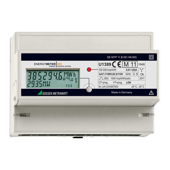
ENERGYMETER
MID
Electronic Active Energy Meters
3-349-618-15
U1281/U1289/U1381/U1387/U1389
3/12.18
MAIN PISTRIBUTION – PRODUCTION
Edited in Germany • Subject to change without notice • A pdf version is available on the Internet
GMC-I Messtechnik GmbH
Südwestpark 15
90449 Nürnberg • Germany
Phone +49 911 8602-111
Fax
+49 911 8602-777
E-Mail
info@gossenmetrawatt.com
www.gossenmetrawatt.com
Advertisement


Need help?
Do you have a question about the MID U1281 and is the answer not in the manual?
Questions and answers